Table of Contents
Advertisement
Advertisement
Table of Contents

Related Manuals for eschmann SES2000

Summary of Contents for eschmann SES2000
- Page 1 SES2000 A UT O CLAVE 699215 ST-SM8l...
- Page 2 Serial Number. (NOTE: The Serial Number Plate is located inside the door in the top left hand corner). For further information visit www.eschmann.co.uk All correspondence relating to the after sales service of Eschmann Equipment to be addressed to : UK Customers Eschmann Equipment, Peter Road, Lancing, West Sussex BN15 8TJ, England.
-
Page 3: Table Of Contents
SES 2000 AUTOCLAVE CONTENTS Page Page Set-up procedure .. 26 Contents .. Autoclave without printer ..26 Technical data .. Autoclave with printer ..26 Setting the Autoclave Serial Number PART 1 INTRODUCTION Entering the Autoclave Serial Number 27 Entering the date and time .. -
Page 4: Technical Data
SES 2000 AUTOCLAVE TECHNICAL DATA (Standard Version) Electrical Data Dimensions Supply 220/230/240V a.c. at 50/60Hz Autoclave Width 460mm 110V a.c. at 50/60Hz Length 461mm Height 360mm Nominal Loading @ 230V - 2kW (8.7A) @ 110V - 1.4kW (12.7A) Chamber Diameter 200mm Length 348mm (max) - Page 5 SES 2000 AUTOCLAVE TECHNICAL DATA (Long Version) Electrical Data Dimensions Supply 230Vac at 50/60Hz Autoclave Width 460mm Length 650mm* Nominal Loading @ 230V - 2.75kW (12A) Height 360mm * Feet spaced to fit 600mm worktop Fuses Chassis 15A, 250V, (x2) Part No. 301871 Chamber Diameter 200mm...
-
Page 6: Part 1 Introduction
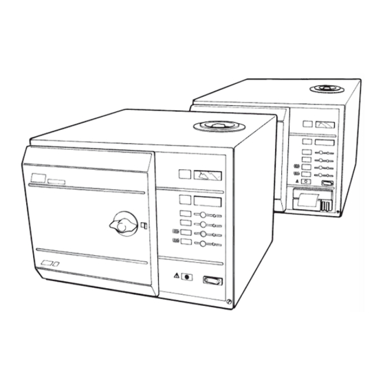
Part 1 SES 2000 AUTOCLAVE PART 1 INTRODUCTION GENERAL (Fig. 1) If ‘Sterile Water for Irrigation’ is not being used then Eschmann strongly recommend the use of either This Manual contains descriptive, distilled water, deionized water, purified water or maintenance and spare parts information for the water treated by the reverse osmosis process. -
Page 7: Part 2 Description
SES 2000 AUTOCLAVE Part 2 PART 2 DESCRIPTION GENERAL (Fig 2) Door Secondary Latch (Fig. 2 item 6). This engages a safety catch to ensure the door does not fly open The autoclave is a portable steam unit heated by should there be residual pressure in the chamber a single element and can be supplied to suit any of the when the door latching handle is operated. - Page 8 Part 2 SES 2000 AUTOCLAVE PART 2 DESCRIPTION from the electrical supply prior to cycle start, and Air Valve (Fig. 3 item 6). At the start of a cycle the following cycle completion, to give additional chamber is full of air, and for a satisfactory result protection.
-
Page 9: Operation Cycle
SES 2000 AUTOCLAVE Part 2 PART 2 DESCRIPTION Integral Printer (Fig. 2 item 22). If the autoclave 2.13 The heater is controlled by a system which has a printer, it will start automatically when the ensures that the operating temperature is reached with programme button is pressed and will print out a minimal overshoot. -
Page 10: Display Messages
Part 2 SES 2000 AUTOCLAVE PART 2 DESCRIPTION 2.19 The overall time for the cycle is not fixed and DISPLAY MESSAGES depends on many factors such as the supply voltage, 2.22 Throughout a given cycle the following symbols the load and the ambient temperature. However, the may appear as a digital display: controller will ensure a satisfactory sterilization cycle even when these factors vary over wide ranges. -
Page 11: Error Indication
SES 2000 AUTOCLAVE Part 2 PART 2 DESCRIPTION ERROR INDICATION 2.24 If an error occurs during a cycle, the controller will cancel the cycle (see Fault Diagnosis, and Errors and General Error Clearing in Part 3). 2.23 If an error should occur during a cycle, one of the following error code symbols will be displayed: Note: If the autoclave has a printer, and if an error occurs during a sterilization cycle, the printer will printout... -
Page 12: Fig. 2 Autoclave General Arrangement
Part 2 SES 2000 AUTOCLAVE PART 2 DESCRIPTION Process display window Pressure display window Control panel Door latching handle Pressure door Secondary door latch Door cover Seal retaining rim Seal retaining disc 10 Door seal 11 ‘O’-ring (on older models) 12 Aerotight nut # 13 Door safety catch 14 Pressure chamber... -
Page 13: Fig. 3 Autoclave: Pipes And Valves
SES 2000 AUTOCLAVE Part 2 PART 2 DESCRIPTION Press to close Push to open Current drain tap. Note correct orientation and location on drain tube. Water fill valve Pressure door lock Discharge valve Reservoir drain tube Pressure gauge Drain tap Chamber manifold Filter unit Safety valve... -
Page 14: Autoclave Heater And Process Controls
Part 2 SES 2000 AUTOCLAVE PART 2 DESCRIPTION Note: Items 4 and 4a are fitted to the underside of chamber manifold but shown here for clarity. 1 Heating element 11 Transformer 2 Thermostat sensor bulb 12 PCB (controller) 3 Cycling thermostat 13 Terminal block 4A Temperature sensor* Power supply cable... -
Page 15: Part 3 Maintenance
SES 2000 AUTOCLAVE Part 3 PART 3 MAINTENANCE FUSES (Fig. 4 and 8 ) The autoclave is protected by four fuses. Three mains supply fuses are fitted on the autoclave back panel (Fig. 4). The fourth fuse (process and control circuits) is fitted on the controller board inside the autoclave (Fig. 8). Printer versions have an extra fuse on the printer PCB. - Page 16 Part 3 SES 2000 AUTOCLAVE PART 3 MAINTENANCE Fault Possible Cause Remedy (b) Pressure in chamber. (b) Switch-on power to release pressure in chamber. (c) Vacuum in chamber. (c) As (b) to open door then clean or replace air valve (section 3.9).
- Page 17 SES 2000 AUTOCLAVE Part 3 PART 3 MAINTENANCE Fault Possible Cause Remedy (7) 'LoH2o' or ‘Error’ (a) No water in chamber (a) Ensure chamber water level displayed before sensor is clear of obstructions. sterilizing temp. Also, ensure sensor is not reached dirty or corroded.
- Page 18 Part 3 SES 2000 AUTOCLAVE PART 3 MAINTENANCE Fault Possible Cause Remedy (10) No discharge of (a) Discharge valve fault (a) Test valve, using ‘Engineering steam/water at Mode’. Replace if faulty end of cycle (b) Wiring fault (b) Ensure connections to discharge valve are sound (c) Blockage in discharge line (c) Strip pipework and clean...
- Page 19 SES 2000 AUTOCLAVE Part 3 PART 3 MAINTENANCE Fault Possible Cause Remedy (16) Excessive noise (a) Positioning of discharge (a) Check cooling coil position from reservoir line in reservoir during discharge incorrect (17) Thermal fuse (a) Failure of heater thermostat (a) Replace heater thermostat blows and cutout to reset automatically...
-
Page 20: Parts Replacement And Adjustment
Part 3 SES 2000 AUTOCLAVE PART 3 MAINTENANCE PARTS REPLACEMENT AND ADJUSTMENT nuts and bolts. The replacement transformer should be an identical unit. To install replacement transformer, WARNING reverse the removal procedure. Switch-off and disconnect mains power supply Controller Board (Fig. 4, item 12) before removing autoclave cover, or doing maintenance procedures. -
Page 21: Air Valve
SES 2000 AUTOCLAVE Part 3 PART 3 MAINTENANCE Air Valve (Fig. 3, item 6) Fit leaf spring (4) to microswitch actuator lever (5), with clamp screw (6) and washer (7). The air valve is fitted in the manifold at the rear of the sterilizing chamber. -
Page 22: Solenoid Door Lock (Ce Only)
Part 3 SES 2000 AUTOCLAVE PART 3 MAINTENANCE Solenoid Door Lock (Fig. 4, item 22) the plate out from the manifold and slide the sensors out CE ONLY see note page 38. of the plate. When removing the sensor carefully note the wire colour positions at the plug (i.e. -
Page 23: Solid State Relay (Ce Only)
SES 2000 AUTOCLAVE Part 3 PART 3 MAINTENANCE Replace varistor across mains terminals of solid Remove two screws securing the interface board sate relay to the partition wall, and remove printer interface board complete with voltage regulator unit. Solid State Relay (Fig. 4 item 8A) Refit printer interface board (complete with rectifier CE ONLY see note page 38. -
Page 24: Discharge Line Filter
Part 3 SES 2000 AUTOCLAVE PART 3 MAINTENANCE SPECIAL OPERATING MODES Demonstration Mode 3.25 Demonstration mode provides a selection of the available display messages for use at exhibitions and for customer education in whatever language has been selected. To enter this mode proceed as follows: Switch off power. -
Page 25: Set-Up Mode
SES 2000 AUTOCLAVE Part 3 PART 3 MAINTENANCE (CE ONLY see note page 38) Button 134°C (with drying). Press to check the solenoid lock retracts. Button 121°C (with drying). To switch on heater, press and hold in this button until ‘HEAt’ or (if hot) temperature display appears, then release. -
Page 26: Set-Up Procedure
Part 3 SES 2000 AUTOCLAVE PART 3 MAINTENANCE Set-Up Procedure Press switch 1 and check that the display changes to ‘Print’. 3.33 After changing the printer interface board, the autoclave must be set-up as follows. Press switch 1 and check that the display changes to ‘CyC-0’... -
Page 27: Entering The Autoclave Serial Number
SES 2000 AUTOCLAVE Part 3 PART 3 MAINTENANCE = January, to 12 = December). Note that on the Entering the Time and Date (Fig. 7) printout, the month will be shown as a letter (A = 3.38 The date and time comprises five elements: January, to L = December). -
Page 28: Errors And Error Clearing
Part 3 SES 2000 AUTOCLAVE PART 3 MAINTENANCE ERRORS AND ERROR CLEARING Autocheck (Printer version only) General 3.43 When the sterilizing phase has been reached a check is automatically made to ensure that the 3.40 Various situations can give rise to an error code temperature recorded on each sensor does not exceed being displayed. -
Page 29: Calibration Procedure
SES 2000 AUTOCLAVE Part 3 PART 3 MAINTENANCE Calibration Procedure (Fig. 8) Note 2 The next adjustment will have to be completed 3.48 The autoclave control programme contains a within approximately three minutes, before two special calibration sequence to ensure accurate ‘bleeps’... -
Page 30: Safety Valve
3.51 It is recommended that adjustments, maintenance and repair of safety valves should only be carried out by Controller Board without Daughter Board Eschmann personnel or accredited agents. Removal and installation of the valve is a straightforward procedure, but on installation, wrap PTFE tape around Fig. -
Page 31: Part 4 Illustrated Parts Lists
SES 2000 AUTOCLAVE Part 4 PART 4 ILLUSTRATED PARTS LIST IMPORTANT NOTE: From SN prefix SCC (std.) and LSCC (long) the pipes and fittings have been changed to those shown in the Schematic Diagram below (i.e. pipes changed from copper to reinforced silicone). ST-SM8l Page 31 of 43... -
Page 32: Fig. 1 Ses 2000 Autoclave
Part 4 SES 2000 AUTOCLAVE PART 4 ILLUSTRATED PARTS LIST 1: PIPES AND VALVES For units with silicone (i.e. not copper) pipes see page 31. Illustration of tap now supplied Fig. 9 Pipes and Valves Fig. 9 Part No Description Qty.Per Recommended Holding Item No Standard... -
Page 33: Illustrated Parts List 2: General Spares
SES 2000 AUTOCLAVE Part 4 Chamber changes on current models: To ensure easy access into the chamber to meet the requirements of PSSR2000, the following parts have been fitted. This enables temperature and pressure measurement at this point. Standard Chamber The Chamber (part number 490040) has been fitted with the following new parts at the top rear port: 427030 ¼"... -
Page 34: Fig. 10 General Spares
Part 4 SES 2000 AUTOCLAVE PART 4 ILLUSTRATED PARTS LIST 2: GENERAL SPARES Fig. 10 General Spares Page 34 of 43 ST-SM8l... - Page 35 SES 2000 AUTOCLAVE Part 4 PART 4 ILLUSTRATED PARTS LIST 2: GENERAL SPARES Fig. 10 Part No Description Qty.Per Recommended Holding Item No Standard Long Unit Per Unit Per Year 490290 490142 Chassis 490310 490144 Top cover 111928 Screw, self tapping 490063 490146 Dividing panel...
-
Page 36: Illustrated Parts List 3: Heater And Process Controls
Part 4 SES 2000 AUTOCLAVE PART 4 ILLUSTRATED PARTS LIST 3: HEATER AND PROCESS CONTROLS Note: Items 9 and 9a are fitted to the underside of chamber manifold but shown here for clarity. Fig. 11 Heater and Process Controls Page 36 of 43 ST-SM8l... - Page 37 SES 2000 AUTOCLAVE Part 4 PART 4 ILLUSTRATED PARTS LIST 3: HEATER AND PROCESS CONTROLS Fig. 11 Part No Description Qty.Per Recommended Holding Item No Standard Long Unit Per Unit Per Year 412012 Heating element 230V, 2kW 416220 Heating element 230V, 2.75kW 412008 Heating element 110V, 1.4kW 425114...
- Page 38 Part 4 SES 2000 AUTOCLAVE PART 4 ILLUSTRATED PARTS LIST 3: HEATER AND PROCESS CONTROLS Fig. 11 Part No Description Qty.per Recommended Holding Item No Standard Long Unit Per Unit Per Year 110249 Transformer with shroud 110250 . Transformer shroud 301478 Solid state relay (not for CE Units**) 1 301481...
-
Page 39: Autoclave Printer
(Fig. A2-2) on The quality and size of paper rolls used in the printer, cartridge, clockwise, using finger or fingernail. can only be supplied by Eschmann Equipment. Fit paper roll as described above. ST-SM8l Page 39 of 43... -
Page 40: Fig. A1-A5 Autoclave Printer Details
A spares pack is available comprising: ♦Five paper rolls ♦Two ribbon cartridges The spares pack is available from Eschmann Equipment please quote REF 87-034-05. Setting Date and Time (Fig. A5) 1. To change the clock setting (e.g. from GMT to BST or the reverse) proceed as follows: a. -
Page 41: Schematic - Pipes And Valves
SES 2000 AUTOCLAVE Appendix B APPENDIX B - Schematic diagram - Pipework and valves ST-SM8l Page 41 of 43... - Page 44 Eschmann Equipment, Peter Road, Lancing, West Sussex, BN15 8TJ, England. Tel: +44 (0) 1903 753322. Fax: +44 (0) 1903 875789. www.eschmann.co.uk...
- Page 45 Appendix C SES 2000 AUTOCLAVE APPENDIX C - Schematic diagram - CE version (see note page 38) Options chart Voltage Overheat Transformer tappings Heater rating neon Relay board 301481 F400mA 230V 230V F10A F10A 100K Varistor OE/BK OE/BK S.S.Relay LONG 230V F15A F15A...
- Page 46 Appendix C SES 2000 AUTOCLAVE APPENDIX C - Schematic diagram - non-CE version (see note page 38) Options chart Voltage Overheat Transformer tappings Heater rating neon F400mA 230V 230V F10A F10A 100K Varistor OE/BK OE/BK S.S.Relay LONG F400mA 100K 230V 230V F15A F15A...
Need help?
Do you have a question about the SES2000 and is the answer not in the manual?
Questions and answers