Ducati Scrambler Owner's Manual
Hide thumbs
Also See for Scrambler:
- Manual (244 pages) ,
- Owner's manual (187 pages) ,
- Instruction manual (49 pages)
Table of Contents
Advertisement
Quick Links
Advertisement
Table of Contents

Related Manuals for Ducati Scrambler


Summary of Contents for Ducati Scrambler
- Page 2 Although the manual includes fully updated information at the time of print, Ducati Motor Holding S.p.A. therefore reserves the right to make changes without prior notification or without incurring obligations. For this reason, you may note discrepancies when comparing some illustrations with your motorcycle.
- Page 3 Owner's manual US/CANADA...
- Page 4 We'd like to welcome you among Ducati enthusiasts and congratulate you on your excellent choice of motorcycle. We imagine you'll be riding your Ducati motorcycle for long trips as well as short daily excursions. Ducati Motor Holding S.p.A. wishes you smooth and enjoyable riding.
-
Page 5: Table Of Contents
California emission control warranty statement Your warranty rights and obligations Manufacturer’s warranty coverage Owner's warranty responsibilities California evaporation emission system Ducati limited warranty on emission control Introduction system Safety guidelines Warning symbols used in the manual Intended use Instrument panel (Dashboard) - Page 6 Partial fuel reserve counter (TRIP FUEL) Entering PIN CODE function for overriding Ambient air temperature (AIR) purposes Errors Error warnings Controls Displayed errors description Position of motorcycle controls Clock Key-operated ignition switch and steering High engine temperature lock Service warning (SERVICE) Left-hand switch OIL SERVICE zero warning Clutch lever...
- Page 7 Riding the motorcycle Tubeless tires Check engine oil level Running-in recommendations Cleaning and replacing the spark plugs Pre-ride checks Cleaning the motorcycle Storing the motorcycle Starting the engine Important notes Moving off Braking Stopping the motorcycle Scheduled maintenance chart Parking Scheduled maintenance chart: operations to be Refueling carried out by the dealer...
- Page 8 Frame Wheels Tires Suspensions Exhaust system Available colors Electric system Routine maintenance record Routine maintenance record...
-
Page 9: Introduction
Safety guidelines Important Your safety and that of others are very important. Possibility of damaging the motorcycle and/or Ducati Motor Holding S.p.A. urges you to ride your its components. motorcycle responsibly. Before using your motorcycle for the first time, Note... -
Page 10: Rider's Obligations
Attention Attention This motorcycle must not be used for towing or Riding under the influence of alcohol or drugs is for the addition of a sidecar, since this may cause a illegal and punishable by law. loss or control and consequent accident. Avoid taking medication before riding the motorcycle This motorcycle carries the rider and can carry a if you have not consulted your doctor about potential... - Page 11 Attention 1) the removal or rendering inoperative by any person, other than for purposes of maintenance, Check the laws applicable to your country. repair, or replacement, of any device or element Riding without a helmet may be punishable by a fine. of design incorporated into any new vehicle for the purpose of noise control prior to its sale or Attention...
-
Page 12: Reporting Of Safety Defects
NHTSA cannot become involved in individual You are strongly recommended to take a riding problems between you, your dealer, or Ducati North course approved by the M.S.F. (Motocycle Safety America. To contact NHTSA, you may either call the Fundation). -
Page 13: Safety "Best Practices
"Riding the Important motorcycle" of this Manual. In any case, avoid wearing loose or floppy Failure to follow these instructions releases Ducati clothing that can become stuck in the motorcycle Motor Holding S.p.A. from any liability whatsoever for parts. - Page 14 Attention Important Failure to perform checks may cause damage to The passenger should always hold on to the the vehicle and serious injury to the rider and/or grab handles under the seat with both hands. passenger. Important Attention Be very careful when maneuvering Start the engine when outdoors or in a well intersections or when riding in areas near exits from ventilated place.
-
Page 15: Refueling
Important Do not smoke or ever use flames during refueling. Be careful never to drop fuel on the engine or exhaust Visually inspect the tires at regular intervals for pipe. cracks and cuts, especially on sidewalls, bulges or When refueling, do not fill the tank completely: fuel large spots which are indicative of internal damage. -
Page 16: Carrying The Maximum Load Allowed
Attention Important Fuel is highly flammable. If it accidentally spills Arrange your luggage or heavy accessories in onto clothes, change them. the lowest possible position and close to motorcycle center. Carrying the maximum load allowed Important Your motorcycle is designed for long-distance riding with the maximum load allowed carried in full safety. -
Page 17: Dangerous Products - Warnings
Please refer to paragraph "Tires" on page 167. Attention The brake fluid used in the brake system is Dangerous products - warnings corrosive. In the event of accidental contact with eyes Used engine oil or skin, wash the affected area with generous quantities of running water. -
Page 18: Vehicle Identification Number
Vehicle identification number Note These numbers identify the motorcycle model and should always be indicated when ordering spare parts. We recommend that you note the frame number (Fig 1) of your motorcycle in the space below. Frame number Fig 1... - Page 19 There are two types of VIN number: VIN (Fig 2) refers DUCATI PLANT OF to vehicles produced in the Italian factory, whereas TYPE OF MANUFACTURE VIN (Fig 3) refers to vehicles produced in the Thai MOTORCYCLE factory. SEQUENTIAL MODEL NUMBER...
-
Page 20: Engine Identification Number
Engine identification number Note These numbers identify the motorcycle model and should always be indicated when ordering spare parts. We recommend that you note the engine number (Fig 4) of your motorcycle in the space below. Engine number Fig 4... -
Page 21: Customizations
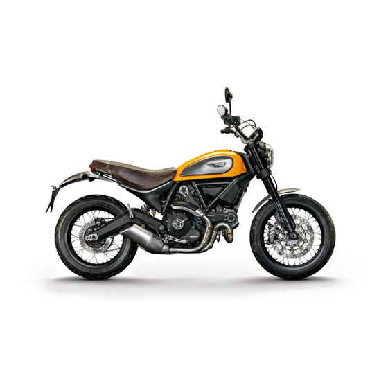
Customizations Each version is a customization of the SCRAMBLER. The SCRAMBLER is available in four different customizations: ICON (A) URBAN ENDURO (B) FULL THROTTLE (C) CLASSIC (D) Information herein refers to Scrambler ICON. Information on any other customization (URBAN ENDURO, FULL THROTTLE, CLASSIC) is indicated only when different from the Scrambler ICON. - Page 22 ICON Fig 6...
- Page 23 ICON 1) Ten-spoke, light-alloy rims 2) Dedicated sticker with logo 3) Dedicated seat...
- Page 24 URBAN ENDURO Fig 7...
- Page 25 URBAN ENDURO 1) Spoked wheel rims 2) Raised front mudguard 3) Sump guard 4) Dedicated sticker with logo 5) Headlight grille as standard 6) Dedicated seat 7) Handlebar crosspiece 8) Front fork guards...
- Page 26 FULL THROTTLE Fig 8...
- Page 27 FULL THROTTLE 1) Dedicated sticker with logo 2) Tailpipe as standard (Termignoni) 3) Lowered handlebar 4) Black anodized side panels 5) Dedicated racing seat 6) Short front mudguard 7) Rear turn indicators with no splash guard...
- Page 28 CLASSIC Fig 9...
- Page 29 CLASSIC 1) Dedicated-thickness logo 2) Aluminum spoked wheel rims 3) Long, satin-finished aluminum front mudguard 4) Long, satin-finished rear mudguard 5) Dedicated seat 6) Raised number plate holder...
-
Page 30: Plate Position
Plate position Fig 10... - Page 31 Girare la ruota posteriore per trovare la posizione in cui la catena risulta più tesa. Appoggiare il veicolo sulla stampella laterale. Con la sola pressione del dito, spingere verso il basso la catena nel punto di misura e poi rilasciarla. Dalla posizione assunta a riposo dalla catena, misurare l’escursione VERSO L’ALTO.
- Page 32 Only Canada Fig 12...
- Page 33 8 (Only Canada ) Fig 13...
-
Page 34: Noise And Exhaust Emission Control System Information
Carbon monoxide does not react in the same way, Problems that may affect motorcycle emissions but is toxic. Ducati utilizes lean carburetor settings If you are aware of any of the following symptoms, and other systems to reduce carbon monoxide and have the vehicle inspected and repaired by your local hydrocarbons. -
Page 35: Manufacturer's Warranty Coverage
Also included may You are responsible for presenting your be hoses, belts, connectors and other emission- motorcycle to a Ducati dealer as soon as a related assemblies. Where a warrantable condition problem exists. The warranty repairs should be exists, Ducati North America, Inc. -
Page 36: California Evaporation Emission System
California evaporation emission system This system consists of: 1) Warn air inlet; 2) Canister; 3) Dell’Orto jet; 4) Fuel tank; 5) Breather pipe; 6) Intake manifolds. Attention In the event of fuel system malfunction, contact Ducati’s authorized Service Centres. Fig 14... -
Page 37: Ducati Limited Warranty On Emission Control System
Air Resources Board. Any part or parts replaced under Ducati North America, Inc., 10443 Bandley Drive this warranty shall become the property of Ducati. In Cupertino, California, 95014 warrants that each new the state of California only, emissions related... - Page 38 Ducati dealer. Ducati shall not be liable A. Repair or replacement required as a result of for any other expenses, loss or damage, whether...
- Page 39 This warranty gives you specific legal rights, and you may also have other rights which vary from state to state. V. This warranty is in addition to the Ducati limited motorcycle warranty. VI. Additional information Any replacement part that is equivalent in performance and durability may be used in the performance of any maintenance or repairs.
-
Page 40: Instrument Panel (Dashboard)
Instrument panel (Dashboard) 6) FUEL WARNING LIGHT (AMBER YELLOW). Turns on when fuel is low and there are about 1.06 gallons (4 liters) of fuel left in the tank. 7) TURN INDICATOR LIGHTS (GREEN). A warning light turns on and blinks when the relevant Instrument panel turn indicator is active;... - Page 41 9) ABS LIGHTS (AMBER YELLOW). This turns on to indicate that ABS is disabled or not functioning. Engine off/ speed below 3 mph (5 km/h) Light off Light flashing Light steady ABS disabled with the menu func- ABS enabled but not working yet tion "ABS"...
- Page 42 10) OVER REV / IMMOBILIZER / ANTI-THEFT SYSTEM (RED) Over rev No intervention Light OFF First threshold (N Light steady ON RPM before the limit- er kicks in) Limiter Light ON flashing Note Each calibration of the Engine Control Unit may have a different setting for the thresholds that precede the rev limiter and the rev limiter itself.
- Page 43 Fig 15...
-
Page 44: Acronyms And Abbreviations Used In The Manual
Acronyms and abbreviations used in the Manual Anti-lock Braking System Controller Area Network DUCATI Data Acquisition Instrument panel Engine Control Unit... -
Page 45: Technological Dictionary
Technological Dictionary Anti-lock Braking System (ABS) 9M ABS 9M system is a two-channel latest-generation system that actuates combined braking with anti lift- up function for the rear wheel so as to guarantee not only a reduced stopping distance, but also a higher stability under braking. -
Page 46: Function Push-Buttons
Function push-buttons 1) CONTROL SWITCH UP " " Button used to display and set instrument panel parameters with the position " ". 2) CONTROL SWITCH DOWN " " Button used to display and set instrument panel parameters with the position " ". -
Page 47: Parameter Setting/Displaying
Parameter setting/displaying Upon key-on, the instrument panel: turns on the display backlighting; activates the rev counter which increases from 0 to 12000 and then goes back to 0; activates the vehicle speed digits and shows a counting from 0 to 300 and then back to 0; turns on the warning lights in a sequence, starting from the right to the left. - Page 48 Data displayed on the main screen are as follows: 1) Engine rpm. 2) Vehicle speed. 3) MENU 1 (Odometer, Trip 1, Trip 2, Trip Fuel, Air temperature, Error indication, only if present). 4) Clock. 5) SERVICE indication (only if active). 6) Setting menu.
- Page 49 From the main screen, press button (2) on LH switch to view Menu 1 information. Odometer (TOT); TRIP 1; TRIP 2; TRIP FUEL (when function is active); T – AIR. Fig 19...
- Page 50 TRIP FUEL displayed, if active. If this condition occurs, contact a Ducati Dealer or Authorized Service Center.
- Page 51 Hold the button (2) for 3 seconds with the actual vehicle speed lower than or equal to 12 mph (20 km/ h) to gain access to the Setting Menu, where you can set any function. Important You can enter the SETTING MENU only when the actual vehicle speed is lower than or equal to 12 mph (20 km/h).
-
Page 52: Main Functions
Main functions The functions displayed in the Standard Screen are the following: Main information Vehicle speed Engine rpm indication (RPM) Menu 1 displays the following functions: - Odometer (TOT) - Trip meter 1 (TRIP 1) - Trip meter 2 (TRIP 2) - Partial fuel reserve counter (TRIP FUEL) - External air temperature (AIR) - Clock... - Page 53 The functions within the Setting Menu that can be modified by the user are the following: PIN CODE (activation and modification of PIN CODE); CLOCK (clock settings); LIGHT (backlighting settings); BATTERY (battery voltage indication); UNITS (units of measurement settings); ABS (ABS control unit enabling - disabling); EXIT (to quit the Setting Menu)
-
Page 54: Motorcycle Speed
Motorcycle speed This function allows displaying the vehicle speed (km/ h or mph according to the specific application). The instrument panel receives information about the actual vehicle speed (calculated in km/h) and displays the value increased by 5% and converted in the set unit of measurement (mph or km/h). -
Page 55: Engine Rpm Indication (Rpm)
Engine rpm indication (RPM) This Function allows displaying engine rpm. Instrument panel receives rpm value and displays it. The information is displayed by the bargraph filling from the right to the left according to the engine rpm. Fig 22... - Page 56 The thresholds before the rpm limiter are: threshold 8900 rpm (A) When the rev limiter value (B) is reached, the warning lights start flashing. Fig 23...
-
Page 57: Menu 1 Functions
Menu 1 functions MENU 1 functions are: Odometer (TOT); Trip meter 1 (TRIP 1); Trip meter 2 (TRIP 2); Partial fuel reserve counter (TRIP FUEL); Ambient air temperature (T-AIR). By pressing button (2) it is possible to view the functions of MENU 1. Fig 24... -
Page 58: Odometer (Tot)
Upon Key-On, the instrument panel always shows the Odometer indication for 10 seconds, then shows the user's settings page. Note If a string of flashing dashes " ----- " is displayed within odometer function, please contact a Ducati Dealer or Authorised Service Centre. -
Page 59: Trip Meter 1 (Trip 1)
Trip meter 1 (TRIP 1) The trip meter counts and displays the partial distance covered by the vehicle with the set unit of measurement (mi or km). When the reading exceeds the maximum value of 9999.9 mi or 9999.9 km, distance traveled is reset and the meter automatically starts counting from 0 again. -
Page 60: Trip Meter 2 (Trip 2)
Trip meter 2 (TRIP 2) The trip meter counts and displays the partial distance covered by the vehicle with the set unit of measurement (mi or km). When the reading exceeds the maximum value of 9999.9 mi or 9999.9 km, distance traveled is reset and the meter automatically starts counting from 0 again. -
Page 61: Partial Fuel Reserve Counter (Trip Fuel)
Partial fuel reserve counter (TRIP FUEL) The fuel trip meter counts and displays the distance covered by the vehicle on reserve (since the low fuel light turns on) with the set unit of measurement (mi or km). When the Low fuel light (A) turns on, the display automatically shows the TRIP FUEL function, regardless of the currently displayed function;... - Page 62 Note Whenever the unit of measurement is changed or in case of power off (Battery Off), the distance traveled is reset and the meter starts counting from zero again (considering the new set units of measurement).
-
Page 63: Ambient Air Temperature (Air)
Ambient air temperature (AIR) The instrument panel displays the ambient temperature in the set unit of measurement (°C or °F), followed by the set unit of measurement, and the T-AIR text. The temperature value is displayed when ranging from -38 °F to +255 °F (or -39 °C to +124 °C). For different temperature values (lower than -38 °F (-39 °C) or higher than +255 °F (+124 °C)) a string of three steady dashes "... -
Page 64: Errors
Errors The instrument panel manages error warnings in order to allow the rider to identify any abnormal vehicle behavior in real time. Upon Key-ON - if there are active errors - or during normal operation of the vehicle - whenever an error is triggered - the instrument panel turns the EOBD light and Warning symbol ON and indicates the triggered error. -
Page 65: Error Warnings
3 seconds. When an error is triggered the EOBD light turns on as well. Attention When one or more errors are displayed, always contact a Ducati Dealer or authorised Service Centre. Fig 32... -
Page 66: Displayed Errors Description
Displayed errors description Displayed error Description ENGINE Throttle position sensor malfunction Throttle motor (stepper motor) or relay malfunction Pressure sensor malfunction Engine coolant temperature sensor malfunction Injection relay malfunction Ignition coil malfunction Injector malfunction Engine rpm sensor malfunction Lambda sensor or Lambda sensor heater malfunction Vehicle starting relay malfunction Secondary air valve malfunction AIR –... - Page 67 Displayed error Description IMMO Generic error DSB control unit faulty communication / operation SD.STND Side stand sensor not working...
- Page 68 Error icons table WARNING LIGHT / ERROR MESSAGE ERROR ENGINE AIR – T. Air temperature sensor BATT. Battery voltage SPEED Speed sensor FUEL Low fuel sensor ABS control unit Can Bus OFF IMMO Immobilizer antenna Instrument panel control unit...
- Page 69 WARNING LIGHT / ERROR MESSAGE ERROR SD.STND Side stand sensor...
-
Page 70: Clock
Clock The instrument panel receives information about the time to be displayed. The instrument panel shows the time in the following format: hh (hours) : mm (minutes); with AM indication (for values ranging between 0:00 and 11:59), or with PM indication (for values ranging between 12:00 and 12:59 and between 1:00 and 11:59). -
Page 71: High Engine Temperature
High engine temperature This Function shows an alert indicating that engine temperature reached high values: warning triggers when engine temperature exceeds 392 °F (200 °C). flashing HI message; steady temperature icon and set unit of measurement (°C or °F). Note When this warning is triggered, the instrument panel will not display the clock until value gets equal to or below 392 °F (200 °C). -
Page 72: Service Warning (Service)
Service warning (SERVICE) This indication shows the user that the bike is due for service and must be taken to a Ducati Authorized Service Center. The service warning indication can be reset only by the Authorized Ducati Service Center during servicing. -
Page 73: Oil Service Zero Warning
"SERVICE", the Oil symbol and the message "OIL" upon each Key-ON; after 5 seconds both the message "SERVICE" and the Oil symbol become steady until Key-OFF or until an Authorized Ducati Service Center performs a reset. Fig 36... -
Page 74: Desmo Service Countdown Warning
DESMO SERVICE countdown warning After OIL SERVICE zero reset (at 600 mi - 1000 km), the instrument panel activates the countdown of the miles (or kilometers) left before the following service operation: DESMO SERVICE. The kilometer count indication is shown upon Key-On for 2 seconds whereas when there are 600 mi (1000 km) left before the next service operation, the indication turns on upon every Key-On for 5 seconds. -
Page 75: Desmo Service Warning
"SERVICE", the Desmo symbol and the message "DESMO" upon each Key-ON; after 5 seconds both the message "SERVICE" and the Desmo symbol become steady until Key-OFF or until an Authorized Ducati Service Center performs a reset. Fig 38... -
Page 76: Setting Menu
Setting menu This menu allows enabling, disabling and setting some vehicle functions. To enter the Setting MENU hold button (3) for 2 seconds, with Key-On and vehicle actual speed (lower than or equal to) 12 mph (20 km/h): once inside this menu, you may no longer view any other function. - Page 77 For safety reasons, the setting menu can be accessed only when Vehicle speed is below or equal to 12 mph (20 Km/h); if this menu is accessed and vehicle speed is above 12 mph (20 Km/h), the instrument panel will automatically quit and shift back to main screen.
- Page 78 Fig 40...
-
Page 79: Abs Control Unit Enabling/Disabling
ABS control unit enabling/disabling This function allows enabling or disabling the ABS system. Enter the Setting MENU. Select the parameter to be customized (ABS), by pressing button (1) or (2). Once desired parameter is highlighted, press CONFIRM MENU button (4). When entering the function, the currently set ABS status will be displayed: On = enabled, Off = disabled. - Page 80 Fig 41...
- Page 81 By setting "–" (Off), the ABS will be disabled and the relevant warning light will start flashing. Important When setting the ABS OFF, Ducati recommends paying particular attention to the braking and riding style. If the ABS is in fault, "Err" is displayed when entering the function and Menu will indicate "NO RQ", since...
-
Page 82: Battery Voltage
Battery voltage This function allows you to check the vehicle battery voltage. Enter the Setting MENU. Select BATTERY option, by pressing button (1) or (2). Once function is highlighted, press CONFIRM MENU button (4). You open the BATTERY Menu. The information will be displayed as follows: if battery voltage is between 11.8 V and 14.9 V the reading will be displayed steady;... - Page 83 If the instrument panel is not receiving battery voltage value, a string of three dashes "- - -" is displayed. To exit the menu and go back to Setting Menu main page, select EXIT and press button (4). Fig 45...
-
Page 84: Instrument Panel Back-Lighting Setting (B.light)
Instrument panel back-lighting setting Note (B.LIGHT) In the event of an interruption of the power supply from the Battery, when power is restored, at This function allows adjusting the backlighting the next Key-On, the backlighting will always be set intensity. by default to maximum brightness. - Page 85 Fig 46...
-
Page 86: Clock Setting Function (Clock)
Clock setting function (CLOCK) Press button (4) to shift to minute setting, minutes will start flashing; This Function allows setting time. each time you press button (2), the digit will To view this function, enter the Setting Menu, use increase by one minute. If you hold button button (1) or (2) to select "CLOCK"... - Page 87 Fig 47...
- Page 88 To confirm (store) the new set time press button (4). The EXIT box starts flashing; press button (4) to go back to the setting menu. Note In case of battery off, when the Voltage is restored and upon next Key-On, clock will have to be set again, i.e.
-
Page 89: Pin Code
The motorcycle owner must activate (store) the PIN code; if there is already a stored PIN, contact an Authorised Ducati Dealer to have the function "reset". To perform this procedure, the Authorised Ducati Dealer may ask you to demonstrate that you are the... - Page 90 Entering the PIN CODE 3) Each time you press the button (1) the displayed number decreases by one (- 1) up to "1" and then To activate the PIN CODE function and enter your starts back from "0"; own PIN CODE you must open the Setting MENU. 4) To confirm the number, press the button (4);...
- Page 91 Fig 48...
- Page 92 Press button (4) to confirm the fourth and last figure: the 4-digit code starts flashing. To memorize the entered PIN, keep button (4) pressed for 3 seconds. If new settings have been saved, "MEM" will be shown and the "EXIT" box will be flashing. Press button (4) to quit.
-
Page 93: Changing The Pin Code
Changing the PIN CODE 1) Press button (4), one digit starts flashing indicating "0"; To change the existing PIN CODE and activate a new 2) Each time you press the button (2) the displayed one, you must open the Setting MENU. number increases by one (+ 1) up to "9"... - Page 94 Fig 50...
- Page 95 After pressing button (4) to confirm the fourth and last Repeat the procedures until you confirm all the four figure, the 4-digit code starts flashing. digits of the PIN CODE. Press button (4) and the system will check the entered PIN CODE. After you press the button: if the PIN CODE is correct (D), the instrument panel shows "OK"...
- Page 96 Fig 51...
- Page 97 Press button (4) to confirm the fourth and last figure: the 4-digit code starts flashing. To memorize the new PIN, keep button (4) pressed for 3 seconds. If new settings have been saved (D), "MEM" will be shown and the "EXIT" box will be flashing. Press button (4) to quit.
-
Page 98: Setting The Unit Of Measurement
Setting the unit of measurement This function allows changing the units of measurement of the displayed values. To manually set the units of measurement, you must enter the SETTING MENU. Select UNITS option, by pressing button (1) or (2). Once function is highlighted, press CONFIRM MENU button (4). - Page 99 Fig 53...
- Page 100 Setting the unit of measurement: Speed Km/h: if this unit is set, the following values will have the same units of measurement: This function allows changing the unit of 1) TOT, TRIP 1, TRIP 2, TRIP FUEL: km measurement of Vehicle speed, Odometer, Trip 1, 2) Vehicle speed: km/h Trip 2 and Trip Fuel (when active).
- Page 101 Fig 54...
- Page 102 Setting the unit of measurement: Temperature °C: if this unit is set, the following values will have the same units of measurement: This function allows you to change the units of 1) T – AIR : °C measurement of the Air Temperature indications. °F: if this unit is set, the following values will have To enter this function gain access to the SETTING the same units of measurement:...
- Page 103 Fig 55...
- Page 104 DEFAULT setting This function allows setting the DEFAULT units of measurement according to the vehicle version. To enter this function gain access to the SETTING MENU, and keys (1) and (2) to select the UNITS indication, then press button (4). Press button (1) or (2) to make the "UNIT:DF"...
-
Page 105: Light Control
Light control Low / High beam This function allows you to reduce current consumption from the battery, by managing headlight switching-on and off. Upon Key-On, low and high beams remain off (OFF). By starting the engine, the low beam will be automatically activated;... - Page 106 The low beam lights are turned on the first time it is is interrupted and will restart when the speed returns pressed; from this moment, the same button can be below the indicated threshold. used to switch on (and off) the high beam light: if the engine is not started within 60 seconds, the low beam and high beam that were turned on will turn off.
- Page 107 Hazard function The "Hazard" function activates all four turn indicators at the same time to warn about an emergency situation. Take button (3) in position (6) for 3 seconds to activate "Hazard" function. It can only be activated when vehicle is on (i.e. when key is turned to "ON", engine condition is irrelevant).
-
Page 108: Immobilizer System
Immobilizer system For improved anti-theft protection, the motorcycle is equipped with an IMMOBILIZER, an electronic system that inhibits engine operation whenever the ignition switch is turned off. Housed in the handgrip of each ignition key is an electronic device that modulates an output signal. When the ignition is turned on this signal is generated by a special antenna incorporated in the switch and changes every time. -
Page 109: Keys
Keys The owner receives 2 keys with the vehicle. These keys contain the "immobilizer system code". The keys (B) are regular ignition keys and are used to: start up the engine; open the fuel tank filler plug; open the seat lock. Attention Separate the keys and use only one of the two to ride the bike. -
Page 110: Operation
When the ignition key is turned to OFF, the immobilizer inhibits engine operation. If the other key does not work out either, contact the Ducati Service network. Attention Strong impacts could damage the electronic components inside the key. During the procedure always use the same key. -
Page 111: Duplicate Keys
Duplicate keys If you need any duplicate keys, contact the Ducati Service network with all the keys you have left. The Ducati Service Center will program all the new keys as well as any keys you already have. You may be asked to provide proof that you are the legitimate owner of the motorcycle. -
Page 112: Entering Pin Code Function For Overriding Purposes
Entering PIN CODE function for overriding purposes In case of key acknowledgment system or key malfunction, the instrument panel allows the user to enter his/her own PIN CODE to temporarily restore vehicle operation. If upon key-on an Immobilizer ERROR occurs, the Instrument panel automatically activates in MENU 1 the possibility to enter the four-digit PIN CODE previously memorized with the relevant function in... - Page 113 Fig 60...
- Page 114 2 minutes (D). After 2 minutes, the instrument panel shows the standard screen and does not allow vehicle starting (E). Important If this procedure is necessary in order to start the vehicle, contact an Authorized Ducati Service Center as soon as possible to fix the problem.
- Page 115 Fig 61...
-
Page 116: Controls
Controls Position of motorcycle controls Attention This section shows the position and function of the controls used to ride the motorcycle. Be sure to read this information carefully before you use the controls. 1) Instrument panel. 2) Key-operated ignition switch and steering lock. 3) LH switch. -
Page 117: Key-Operated Ignition Switch And Steering Lock
Key-operated ignition switch and steering lock It is located in front of the fuel tank and has four positions: : enables lights and engine operation; : disables lights and engine operation; : the steering is locked; : parking light and steering lock. Note To move the key to the last two positions, press Fig 63... -
Page 118: Left-Hand Switch
Left-hand switch 1) Dip switch, light dip switch, two positions: position = low beam on (A); position = high beam on (B); Button = high-beam flasher (FLASH) and instrument panel control (C). 2) Switch = 3-position turn indicator control: central position = off; position = left turn;... -
Page 119: Clutch Lever
Clutch lever Lever (1) disengages the clutch. When the clutch lever (1) is operated, drive from the engine to the gearbox and the drive wheel is disengaged. Using the clutch properly is essential to smooth riding, especially when moving off. Important Using the clutch properly will avoid damage to transmission parts and spare the engine. - Page 120 Clutch control free play adjustment Attention A wrong adjustment can seriously affect the clutch operation and duration. A worn clutch makes the clutch cable tension increase. Always check the free play, with cold engine, before using the vehicle. When operating the clutch lever, you must clearly feel the passage from a very low resistance to a very high Fig 67 resistance (operating force).
- Page 121 In case of a slipping clutch due to clutch wear, adjuster (2) on the lever must NEVER be loosened, but screwed, as described above. If the clutch is still slipping, go to a Dealer or a Ducati Authorized Service Center. Fig 68...
-
Page 122: Right-Hand Switch
Right-hand switch 1) Red ON/OFF switch. 2) Black ENGINE START button. The switch (1) has three positions: A) center: RUN OFF. In this position, the engine cannot be started and all electronic devices are off. B) pushed down: ON/OFF. In this position, the system can be turned on (Key-On) and off (Key-Off). -
Page 123: Throttle Twistgrip
Throttle twistgrip The twistgrip (1) on the right handlebar opens the throttles. When released, it will spring back to the initial position (idling speed). Fig 72... -
Page 124: Front Brake Lever
Front brake lever Pull in the lever (1) towards the twistgrip to operate the front brake. The system is hydraulically operated and you just need to pull the lever gently. The control lever features a dial adjuster (2) for lever distance from the twistgrip on handlebar adjustment. -
Page 125: Rear Brake Pedal
Rear brake pedal Push down the pedal (1) to operate the rear brake. The system is hydraulically operated. Fig 74... -
Page 126: Gear Change Pedal
Gear change pedal When released, the gear change pedal automatically returns to rest position N in the center. This is indicated by the instrument panel light N coming on. The pedal can be moved: down = press down the pedal to engage the 1 gear and to shift down. -
Page 127: Adjusting The Position Of The Gearchange Pedal And Rear Brake Pedal
Adjusting the position of the gearchange pedal and rear brake pedal The position of the gearchange and rear brake pedals in relation to the footrests can be adjusted to suit the requirements of the rider. Adjust the pedals as follows: Gear change pedal hold the linkage (1) and slacken the lock nuts (2) and (3). - Page 128 Rear brake pedal Loosen counter nut (4). Turn pedal stroke adjusting screw (5) until pedal is in the desired position. Tighten the counter nut (4). Operate the pedal by hand to check that there is about 0.06-0.08 in (1.5-2 mm) of free play before the brake bites.
-
Page 129: Main Components And Devices
Main components and devices Position on the vehicle 1) Tank filler plug. 2) Seat lock. 3) Side stand. 4) Rear-view mirrors. 5) Rear shock absorber adjusters. 6) Catalytic converter. 7) Exhaust silencer. Fig 79... -
Page 130: Fuel Tank Plug
Fuel tank plug Opening Insert the key into the lock. Turn the key clockwise 1/4 turn to unlock. Loosen plug (1). Closing Screw the cap (1) with the key inserted and press it into its seat. Turn the key counter clockwise to the original position and remove it. -
Page 131: Seat Lock
Seat lock Opening Insert the key (1) in the lock, turn clockwise while pressing down at the latch to help release the pin. Remove the seat (2) pulling it backwards until sliding it out of the front retainers. Closing Make sure that all elements are correctly positioned and fastened to the compartment under the seat. -
Page 132: Side Stand
Side stand Important Use the side stand to support the motorcycle only during short stops. Before lowering the side stand, make sure that the supporting surface is hard and flat. Do not park on soft or pebbled ground or on asphalt melted by the sun, etc. -
Page 133: Usb Connection
USB connection The motorcycle is provided with a 5 V USB connection. It is possible to connect electric loads up to 1 A to the USB connection. The USB connection (1) is located under the seat and is protected by a cover: to use the connection, lift the cover. -
Page 134: Adjusting The Rear Shock Absorber
Adjusting the rear shock absorber The rear shock absorber has commands that enable you to adjust the setting to suit the load on the motorcycle. Ring nut (A), located in the shock absorber upper side, adjusts the external spring preload. To change spring preload, turn the ring nut (A) using the supplied pin wrench, and align ring nut cam with the reference notch (B). - Page 135 Attention To turn the preload adjuster ring nut use the wrench supplied with the tool kit. Pay attention to avoid hand injuries by hitting motorcycle parts in case the wrench tooth suddenly slips on the ring nut groove while moving it. Attention The shock absorber is filled with gas under pressure and may cause severe damage if taken apart...
-
Page 136: Riding The Motorcycle
Riding the motorcycle friction material on the brake pads to bed in against the brake disks. So that the mechanical parts of the motorcycle can adapt to each another, and especially so the life of the basic engine parts is not affected, avoid harsh Running-in recommendations accelerations and do not run the engine at a high rpm for an extended time, especially uphill. - Page 137 Warranty Booklet. Failure to follow these 1000 ÷ 2500 Km 0 ÷ 1000 Km instructions releases Ducati Motor Holding S.p.A. 600 ÷ 1553 mi 0 ÷ 600 mi from any liability whatsoever for any engine damage Fig 88 or shorter engine life.
-
Page 138: Pre-Ride Checks
Pre-ride checks LIGHTS AND INDICATORS Make sure lights, indicators and horn work properly. Replace any burnt-out bulbs (page 103). Attention KEY LOCKS Failure to carry out these checks before riding Ensure that fuel filler plug (page 128) and seat may lead to motorcycle damage and injury to rider (page 129) are locked. - Page 139 When the vehicle speed exceeds 3 mph (5 km/h), the warning light switches off to indicate the correct operation of the ABS. Attention In case of malfunction, do not ride the motorcycle and contact a Ducati Dealer or Authorized Service Center. Fig 89...
-
Page 140: Abs
Check that the front (1) and rear (2) phonic wheels are clean. Attention Clogged reading slots would compromise system proper operation. It is advisable to disable ABS in case of very muddy road surfaces, as in these conditions the system might be subject to sudden failure. -
Page 141: Starting The Engine
Starting the engine Attention Before starting the engine, become familiar with the controls you will need to use when riding. Attention Never start or run the engine indoors. Exhaust gases are poisonous and may lead to loss of consciousness or even death within a short time. Move the ignition key to position (1, Fig 92). - Page 142 Attention The side stand must be fully up (in a horizontal position), as its safety sensor prevents engine start when down. Note The engine can be started with side stand down and the gearbox in neutral. When starting the bike with a gear engaged, pull the clutch lever (in this case the side stand must be up).
-
Page 143: Moving Off
Moving off Attention 1) Disengage the clutch by squeezing the clutch Avoid harsh accelerations, as this may lead to lever. misfiring and transmission snatching. The clutch 2) Push down the gear change lever firmly with the lever should not be pulled longer than necessary after tip of your foot to engage first gear. -
Page 144: Braking
Braking control unit keeps controlling the brake until the risk of a lockup disappears. Slow down in time, shift down to engine-brake first Normally, the rider will perceive ABS operation as a and then brake applying both brakes. Pull the clutch harder feel or a pulsation of the brake lever and pedal. - Page 145 Attention When ABS is disabled, the vehicle restores the standard brake system features; using the two brake controls separately reduces the motorcycle braking efficiency. Never use the brake controls harshly or suddenly as you may lock the wheels and lose control of the motorcycle.
-
Page 146: Stopping The Motorcycle
Stopping the motorcycle Reduce speed, shift down and release the throttle twistgrip. Shift down to engage first gear and then neutral. Apply the brakes and bring the motorcycle to a complete stop. To switch the engine off, simply turn the key to position (2). -
Page 147: Parking
Parking Park the stopped motorcycle on the side stand. To prevent theft, turn the handlebar fully left and turn the ignition key to position (3). If you park in a garage or other indoor area, make sure that there is proper ventilation and that the motorcycle is not near a source of heat. -
Page 148: Refueling
Refueling Never overfill the tank when refueling. Fuel should never be touching the rim of filler (1) recess. Attention Use fuel with the lowest octane rating 90 (RON +MON)/2 Attention The vehicle is compatible only with fuel having a maximum ethanol content of 10% (E10). Using fuel with ethanol content over 10% is Fig 97 prohibited. -
Page 149: Tool Kit And Accessories
Tool kit and accessories The tool kit (1) is located under the seat. Tool kit includes: screwdriver; screwdriver handgrip; Allen wrench, 0.12 in (3 mm); Allen wrench, 0.16 in (4 mm); preload adjustment wrench; handgrip for preload adjustment wrench. To access the compartment, remove the seat page 129. -
Page 150: Main Maintenance Operations
Brake and clutch fluid must be topped up and changed at the intervals specified in the scheduled maintenance table contained in the Warranty Booklet; please contact a Ducati Dealer or Authorized Service Center. Important All brake and clutch lines should be changed every four years. -
Page 151: Changing The Air Filter
If you note too much play on brake lever or pedal and brake pads are still in good condition, contact your Ducati Dealer or Authorized Service Center to have the system inspected and any air drained out of the circuit. -
Page 152: Checking Brake Pads For Wear
Friction material wear beyond this limit would lead to metal support contact with the brake disc thus compromising braking efficiency, disc integrity and rider safety. Fig 103 Important Have the brake pads replaced at a Ducati Dealer or Authorized Service Center. Fig 104... -
Page 153: Charging The Battery
Charging the battery Attention Have the battery removed at a Ducati Dealer or Authorized Service Center. To reach the battery, remove the seat page 129 and remove battery cover (A), after disengaging rubber band (C) and loosening screw (D). Loosen the screws... - Page 154 Charge the battery in a ventilated room. If the motorcycle must be jump-started in an Connect the battery charger leads to the battery emergency with an external starting device, it is terminals: the red one to the positive terminal (+), the possible to connect the external device to the battery black one to the negative terminal (-).
- Page 155 Charging and maintenance of the battery during winter storage Your motorcycle is equipped with a connector (1), located under the seat, to which you can connect a special battery charger (2) (Battery maintenance kit part no. 69924601A - various countries; Battery maintainer kit part no.
- Page 156 Note When the motorcycle is left unused (approximately for more than 30 days) we recommend owners to use the Ducati battery charge maintainer (Battery maintainer kit part no. 69924601A - various countries; Battery maintainer kit part no. 69924601AX - for Japan, China and Australia only) since its electronics monitors the battery voltage and features a maximum charge current of 1.5 Ah.
-
Page 157: Lubricating Cables And Joints
Their external plastic sheath should be free of cracking or flattening. Operate the control to make sure cable slides smoothly: have it replaced by a Ducati Dealer or Authorized Service Center if you find friction or hard spots. For trouble-free operation, periodically lubricate the ends of all Bowden cables with SHELL Advance Grease or Retinax LX2. -
Page 158: Adjusting The Throttle Cable
Adjusting the throttle cable The throttle grip must have a free play of 0.08÷0.16 in (2÷4 mm) in all steering positions, measured on the outer edge of the twistgrip; this value is indicated in the figure as reference (A). To adjust, work the relevant adjuster (1) located on the control itself. -
Page 159: Checking Drive Chain Tension
Checking drive chain tension Important Have chain tension adjusted by a Ducati Dealer or Authorized Service Center. Turn the rear wheel until you find the position where chain is tightest. Set the vehicle on the side stand. With just a finger, push down the chain at the point of measurement and release. - Page 160 Attention Correct tightening of swinging arm screws (1) is critical to rider and passenger safety. Important Improper chain tension will lead to rapid wear of transmission parts. Check the correspondence of the positioning marks on both sides of the swinging arm to ensure a perfect wheel alignment.
-
Page 161: Lubricating The Drive Chain
Lubricating the drive chain The chain fitted on your motorcycle has O-rings to protect its moving parts from dirt and to hold the lubricant inside. The seals might be irreparably damaged if the chain is cleaned using any solvent other than those specific for O-ring chains or washed using steam or water cleaners. -
Page 162: Replacing The Headlight Bulbs
Replacing the headlight bulbs Important Have the bulbs replaced at a Ducati Dealer or Authorized Service Center. Attention The headlight might fog up if the vehicle is used under the rain or after washing. Switch headlight on for a short time to dry up any condensate. - Page 163 Loosen screw (3). Tilt headlight towards the front mudguard and duly support it while loosening screws (4) on light cover (5) and remove cover. Fig 114 Fig 115...
- Page 164 Disconnect connector (6). Release the clip (7). The bulb (8) is the banjo-type: press and rotate counterclockwise to remove. Fit the spare bulb by pressing and turning clockwise until it clicks. Note Do not touch the transparent part of the new bulb with the hands.
-
Page 165: Changing The Turn Indicator Bulbs
Changing the turn indicator bulbs To change the front/rear turn indicator bulbs, loosen the screw (1) and remove the lens (2). Fig 118 Fig 119... -
Page 166: Aligning The Headlight
Aligning the headlight Note The headlight features a double adjustment, one for the right-hand and one for the left-hand light beam. To check the headlight aim, place the motorcycle upright with the tires inflated to the correct pressure 10 m and one person sitting astride the motorcycle. - Page 167 Aligning the headlight The vertical alignment of the headlight can be manually set by turning screw (1). Important Headlight beam adjuster screw has no limit stop. Attention The headlight might fog up if the vehicle is used under the rain or after washing. Switch headlight on Fig 121 for a short time to dry up any condensate.
-
Page 168: Adjusting The Rear-View Mirrors
Adjusting the rear-view mirrors Manually adjust rear-view mirror (A) to required position. Fig 122... -
Page 169: Tubeless Tires
Note When traveling very bumpy roads, increase tire pressure by 0.2÷0.3 bar to preserve the roundness of Have the tires replaced at a Ducati Dealer or the front rim. Authorized Service Center. Correct removal and installation of the wheels is essential. Some parts of... - Page 170 Measure tread depth (S, Fig 123) at the point where tread is most worn down: It should not be less than 0.08 in (2 mm), and in any case not less than the legal limit. Important Visually inspect the tires at regular intervals for cracks and cuts, especially on sidewalls, bulges or large spots which are indicative of internal damage.
-
Page 171: Check Engine Oil Level
Refit the plug. Important Engine oil and oil filters must be changed by a Fig 124 Ducati Dealer or Authorized Service Center at the intervals specified in the scheduled maintenance chart contained in the Warranty Booklet. - Page 172 Viscosity SAE 15W-50 The other viscosity degrees indicated in the table can be used if the local average temperature is within the limits specified for that oil viscosity. 20W–40 20W–50 15W–40 15W–50 10W–40 10W–30 –10 40 C Fig 125...
-
Page 173: Cleaning And Replacing The Spark Plugs
Cleaning and replacing the spark plugs Spark plugs are essential to smooth engine running and should be checked at regular intervals. Have the spark plug replaced at a Ducati Dealer or Authorized Service Center. Fig 126... -
Page 174: Cleaning The Motorcycle
Cleaning the motorcycle Important To preserve the finish of metal parts and paintwork, Do not wash your motorcycle right after use. wash and clean your motorcycle at regular intervals When the motorcycle is still hot, water drops will according to the road conditions you ride in. Use evaporate faster and spot hot surfaces. - Page 175 Attention The headlight might fog up due to washing, rain or moisture. Switch headlight on for a short time to dry up any condensate. Carefully clean the phonic wheels of the ABS to ensure system efficiency. Do not use aggressive products in order to avoid damaging the phonic wheels and sensors.
-
Page 176: Storing The Motorcycle
Storing the motorcycle Periodically carry out the required checks and replace parts as necessary using Ducati original spare parts If the motorcycle is to be left unridden over long to be in compliance with regulations in the given periods, you should perform the following country. -
Page 177: Scheduled Maintenance Chart
Scheduled maintenance chart Scheduled maintenance chart: operations to be carried out by the dealer List of operations and type of interven- Km. x1000 Time tion (months) mi. x1000 0.6 22.5 [set mileage (km/mi) or time interval *] Reading of the error memory with DDS and check of software version update on control units Check the presence of any technical updates and recall campaigns... - Page 178 List of operations and type of interven- Km. x1000 Time tion (months) mi. x1000 0.6 22.5 [set mileage (km/mi) or time interval *] Check the proper tightening of brake caliper bolts and brake disk flange screws Check front and rear wheel nuts tightening Check frame-to-engine fasteners tightening Check wheel hub bearings Check and lubricate the rear wheel shaft...
- Page 179 List of operations and type of interven- Km. x1000 Time tion (months) mi. x1000 0.6 22.5 [set mileage (km/mi) or time interval *] Visually check the fuel lines Check rubbing points, clearance, freedom of movement and positioning of hoses and electric wiring in view Lubricate the levers at the handlebar and pedal controls Check tire pressure and wear Check the battery charge level...
- Page 180 List of operations and type of interven- Km. x1000 Time tion (months) mi. x1000 0.6 22.5 [set mileage (km/mi) or time interval *] Check spoked wheel rims as described in the workshop manual * Service operation to be carried out in accordance with the specified distance or time intervals (km, miles or months), whichever occurs first.
-
Page 181: Scheduled Maintenance Chart: Operations To Be Carried Out By The Customer
Scheduled maintenance chart: operations to be carried out by the customer Km. x1000 List of operations and type of intervention [set mileage (km/mi) or time mi. x1000 interval *] Months Check engine oil level Check brake fluid level Check tire pressure and wear Check the drive chain tension and lubrication Check brake pads. -
Page 182: Technical Data
Technical data Weights Overall weight (in running order with 90% of fuel - 93/93/EC): 410 lb (186 kg) (ICON); 423 lb (192 kg) (URBAN ENDURO); 410 lb (186 kg) (FULL THROTTLE); 411 lb (186.5 kg) (CLASSIC); Overall weight (without fluids and battery): 374.8 lb (170 kg) (ICON);... -
Page 183: Overall Dimensions
Overall dimensions 855 mm / 33.66 in 170 mm 300 mm 6.69 in 11.81 in 1450 mm / 57.09 in 2100 mm/82.68 in / 2140 mm/84.25 in Fig 127... - Page 184 Whenever values are indicated with a letter, please refer to the following list: A) Scrambler ICON B) Scrambler URBAN ENDURO C) Scrambler FULL THROTTLE D) Scrambler CLASSIC...
-
Page 185: Top-Ups
Top-ups TOP-UPS TYPE Fuel tank, including a reserve of 1.05 gal- Unleaded fuel with a minimum octane rat- 3.56 gallons (13.5 cu. ing of 90 (RON+MON)/2. lons (4 cu. dm liters) dm liters) Oil sump and filter SHELL - Advance 4T Ultra 0.9 gallons - (3.4 cu. -
Page 186: Engine
Engine Twin cylinder, four-stroke, 90° "L" type, longitudinal. Bore: 3.46 in (88 mm). Stroke: 2.6 in (66 mm). Total displacement, cu. cm: Compression ratio: 11±0.5:1 Max. power at crankshaft (95/1/EC): 55 kW - 74 CV at 8.250 rpm Max. torque at crankshaft (95/1/EC): 68 Nm - 6.9 Kgm at 5.750 rpm. -
Page 187: Timing System
Timing system DESMODROMIC system with two valves per cylinder controlled by four rocker arms (two opening and two closing ones) and one overhead camshaft. This system is driven by the crankshaft through spur gears, pulleys and toothed belts. Desmodromic timing system 1) opening (or upper) rocker;... -
Page 188: Performance
Important +MON)/2. Failure to follow these instructions will release Attention Ducati Motor Holding S.p.A. from any liability for any engine damage or shortened engine life. The vehicle is compatible only with fuel having a maximum ethanol content of 10% (E10). -
Page 189: Transmission
Hydraulically operated by a control lever on handlebar Transmission right hand side. Wet clutch controlled by the lever on left hand side Brake caliper make: BREMBO. of the handlebar. Type: M4.3 pistons. Drive is transmitted from engine to gearbox main Friction material: TT 2182 FF. -
Page 190: Frame
Trail in mm: 112 Attention If the rear sprocket needs replacing, contact a Wheels Ducati Dealer or Authorized Service Center. Ten-spoke, light-alloy rims (ICON, FULL THROTTLE). If improperly replaced, this component could Spoked wheel rims (URBAN ENDURO, CLASSIC) seriously endanger your safety and that of your... -
Page 191: Exhaust System
The whole system gives the bike Matt Black wheel rims PEHADUR EINBRENN-LACK excellent stability. VPCH03352 (Peter Lacke) Shock absorber stroke: 2.4 in (61 mm). Scrambler URBAN ENDURO Rear wheel travel: 5.9 in (150 mm). Wild Green Exhaust system Primer code DS20054 (LECHLER);... - Page 192 Charcoal black frame AKZO NOBEL code MY/ 2/9611AV Matt Black wheel rims PEHADUR EINBRENN-LACK VPCH03352 (Peter Lacke) Scrambler CLASSIC Orange Sunshine Primer code DS20052 (LECHLER); Base coat code 2909041 (LECHLER); Clear coat code 96230 (LECHLER); Charcoal black frame AKZO NOBEL code MY/...
-
Page 193: Electric System
Electric system Fuses Basic electric items are: There are seven fuses that protect the electric Headlight: components located inside the fuse box, and one on low/high beam: H4 bulb (12V – 60/55W); the electric solenoid starter. The fuse box includes parking light: no. - Page 194 The fuse box (A, Fig 129) is located under the seat so it is necessary to remove the seat and the battery cover to reach it. To expose the fuses, lift the box protective cover. Mounting position and ampere capacity are marked on box cover. Fuse box key El.
- Page 195 The main fuse (C) is positioned on the solenoid starter (D). Remove the fuse cap (E) to reach it. A blown fuse is identified by the interrupted center link (F). Important Switch the ignition key to OFF before replacing the fuse to avoid possible short-circuits. Attention Never use a fuse with a rating other than specified.
- Page 196 Injection /electric system diagram key Horizontal lambda sensor Horizontal spark plug Front stop switch Horizontal coil Clutch switch Vertical spark plug Right-hand switch Vertical coil Key switch Horizontal injector Left-hand switch Vertical injector Fuse box Potentiometer motor (TPS) Mobile phone power socket Secondary air actuator Bluetooth Module MAP sensor...
- Page 197 RH heated handgrip Front left turn indicator Headlight Front right turn indicator Horn Wire color coding B Blue W White V Violet Bk Black Y Yellow R Red Lb Light blue Gr Gray G Green Bn Brown O Orange P Pink Note The electric system wiring diagram is at the end of this manual.
-
Page 198: Routine Maintenance Record Routine Maintenance Record
Routine maintenance record Routine maintenance record NAME MILEAGE DATE DUCATI SERVICE 1000 12000 7500 24000 15000 36000 22500 48000 30000 60000 36000... - Page 200 Y/Gr P/Bk Bk/G P/Bk R/Bk Bk/G W/Bk Gr/R Bk/G W/Bk Bk/G Bk/G 2 3 4 5 Bn/W Bn/W Bn/W Bn/Bk Bn/W Bn/W Lb/W Bk/V Bk/V Bn/W Bn/G Bn/W Bk/V Bn/W Gr/B Gr/G Bk/G 1 2 3 4 Gr/R Scrambler...
Need help?
Do you have a question about the Scrambler and is the answer not in the manual?
Questions and answers