
Related Manuals for Safewatch QuickConnect Plus

Summary of Contents for Safewatch QuickConnect Plus
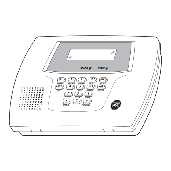
- Page 1 ® ® ® ® Safewatch QuickConnect Plus Security System Programming Guide ARMED READY STAY ESCAPE RECORD VOLUME PLAY DELETE AWAY TEST BYPASS SELECT CODE CHIME STATUS FUNCTION 800-03859-4V2 11/10 Rev. A...
-
Page 2: Table Of Contents
Safewatch QuickConnect Plus Control Defaults.....................23 Safewatch QuickConnect Plus Summary of Connections Diagram ...............24 Refer to the Safewatch QuickConnect Plus Installation and Setup Guide P/N 800-03857-4 or later for detailed information on programming the system. The Installation and Setup Guide contains full descriptions for all data fields. -
Page 3: Data Fields
To Initialize Download ID and Subscriber Account Number for Downloading: 96 Resets all subscriber account numbers and CSID in preparation for an initial download. To Load a Default Set: 97 Enter a number 1-4 corresponding to the selected default table (See the Installation Instructions for the default tables). -
Page 4: Zone Sounds And Timing
DING DING DING after being Armed Away. If Safewatch QuickConnect Plus is armed by RF button (key fob), a confirmation ding occurs immediately after arming regardless of field 38 settings. If Safewatch QuickConnect Plus is disarmed by RF button (key fob), additional disarming confirmation ding occurs immediately after disarming and is longer than arming confirmation ding. -
Page 5: Dialer Programming
Data Field Display Function& Programming Options [ ] = Programmed Table 1 Default Values Cross Zone Timer 39 39 39 39 † [0] CROSS ZONE TIMER CROSS ZONE TIMER CROSS ZONE TIMER CROSS ZONE TIMER Value Time Window Value Time Window No Cross Zoning 2 minutes 15 seconds... - Page 6 Data Field Display Function& Programming Options [ ] = Programmed Table 1 Default Values “Follow Me” Reminder Phone Number 46 46 46 46 FOLLOW ME PHONE FOLLOW ME PHONE FOLLOW ME PHONE FOLLOW ME PHONE Enter up to 24 digits; Do not fill unused spaces. If fewer than 24 digits entered, pressing 6 advances to the next field.
- Page 7 Data Field Display Function& Programming Options [ ] = Programmed Table 1 Default Values Periodic Test Report (enter Test Code in field 664) 51 51 51 51 † [0] PERIOD PERIOD T T T T EST EST REP PERIOD PERIOD 0 = none;...
-
Page 8: Restore Report Codes
Data Field Display Function& Programming Options [ ] = Programmed Table 1 Default Values SYSTEM STATUS REPORT CODES (659–668) Exit Error Report Code 59 59 59 59 2nd digit is automatically sent as 2nd digit of the zone alarm report EXIT EXIT ERROR ERROR REP... -
Page 9: Dynamic Signaling Field
Data Field Display Function& Programming Options [ ] = Programmed Table 1 Default Values Low Bat Restore Report Code 74 74 74 74 [1,0] LO LO LO LO BAT BAT RES RES REP RF Transmitter Low Battery Restore Report Code 75 75 75 75 [1,0] RF RF RF RF LOBAT... -
Page 10: Download Information
Data Field Display Function& Programming Options [ ] = Programmed Table 1 Default Values Event Logging Note: System messages are logged when 90 90 90 90 any non-zero selection is made. EVNT LOG OPTIONS EVNT LOG OPTIONS EVNT LOG OPTIONS EVNT LOG OPTIONS 0 = None;... -
Page 11: Enhanced Zone Programming
6 6 6 6 56 ENHANCED ZONE PROGRAMMING PROCEDURE This interactive menu mode is used to program zone numbers, zone types, alarm and report codes, and to identify the type of loop input device and can be used for entering 5800 Series transmitter serial numbers. Press 656 while in programming mode. - Page 12 6 6 6 6 56 ENHANCED ZONE PROGRAMMING PROCEDURE Enroll Loop Number or Loop & Serial Number via RF Learning (Continued) 1 1 1 1 AL AL AL AL A094 A094- - - - 4129 4129 A094 A094 4129 4129 The serial number of the device that has been learned will be displayed.
- Page 13 6 6 6 6 56 ENHANCED ZONE PROGRAMMING PROCEDURE Voice Descriptor 1 1 1 1 C C C C 0 = Skip to next zone (A) ZONE DESCRIPTOR ZONE DESCRIPTOR ZONE DESCRIPTOR ZONE DESCRIPTOR 1 = Enter descriptor mode (existing zone descriptor will be announced, then descriptor 1 will be repeated) Descriptor 1 1 1 1 1 d...
-
Page 14: Enhanced Zone Programming Worksheet
6 6 6 6 56 ENHANCED ZONE PROGRAMMING WORKSHEET Fill in the required data on this worksheet, then follow the programming procedure. ZONES ON CONTROL: See explanation of headings (defaults shown are for Table 1) Zone Zone No. Zone Alarm rpt code Vocabulary Description (A 01) - Page 15 6 6 6 6 56 ENHANCED ZONE PROGRAMMING WORKSHEET Button Zones Zone No. Zone Alarm Report Input Loop Transmitter Vocabulary (A 01) Type (zt) Code in hex (rc) Type (i) No. (l) Serial Number Index [21] [01 00] [22] [01 00] [20] [01 00] [23]...
-
Page 16: Device Programming
6 6 6 6 80 DEVICE PROGRAMMING Use this mode to program Powerline Carrier Devices or zone lists for Chime by Zone feature. It is also used to program the Remote Services Multi-mode (e-mail) event triggers. Press 80 while in programming mode. Note: Entering a number other than the one specified may give unpredictable results. -
Page 17: Zone Lists
6 6 6 6 81 ZONE LISTS Use this mode to define zone lists for Powerline Carrier Devices and/or for the chime by zone feature. Press while in programming mode. Note: Entering a number other than the one specified may give unpredictable results. Zone List Programming 81 81 81 81 0 = Exit mode, upon which this prompt blinks. -
Page 18: Output Devices
POWERLINE CARRIER DEVICES WORKSHEET FOR 6 6 6 6 80 and 6 6 6 6 81 Applicable only if Powerline Carrier Devices are to be used, or chime-by-zone feature is used. Powerline Carrier Devices have not been evaluated by UL. 680 OUTPUT DEVICES Fill in the required data on the worksheet on below and follow the programming procedure in the Installation Instructions as you enter the data during the displays and prompts that appear in sequence. -
Page 19: Enhanced Sequential Mode
6 6 6 6 83 ENHANCED SEQUENTIAL MODE Use this mode to enter transmitter serial numbers. Press 683 while in programming mode. Enhanced Sequential Mode 83 83 83 83 0 = Exit mode, upon which this prompt blinks. ENHANCD ENHANCD ENHANCD ENHANCD SEQ SEQ MODE... -
Page 20: Assign Zone Voice Descriptors
6 6 6 6 84 ASSIGN ZONE VOICE DESCRIPTORS Use this mode to assign voice descriptors for each zone. These are the descriptors that are announced when the system announces any event involving a zone number. Press 84 while in programming mode. Note: Entering a number other than the one specified may give unpredictable results. -
Page 21: Record Custom Voice Descriptors
6 6 6 6 85 RECORD CUSTOM VOICE DESCRIPTORS Use this mode to record up to 5 custom voice descriptors for use with zone announcements. Press 85 while in programming mode. NOTE: Entry of a number other than one specified will give unpredictable results. Record Custom Voice Descriptors 85 85 85 85 0 = Exit mode, upon which this prompt blinks. - Page 22 5800 SERIES LOOP NUMBERS LOOP 1 LOOP 1 (LOW (LOW SENSITIVITY SENSITIVITY LOOP 2 LOOP 2 LOOP LOOP 1 (HIGH (HIGH SENSITIVITY) SENSITIVITY) LOOP 3 (TEMP) LOOP 3 (TEMP) LOOP 4 (TAMPER) LOOP 4 (TAMPER) 5 8 0 0 R L 5 8 0 0 C O 5 8 0 0 M i c r a 5 8 0 0 P I R - R E S...
-
Page 23: Safewatch Quickconnect Plus Control Defaults
Safewatch QuickConnect Plus Control Defaults Function Default Installer code 6321 Quick arm enable Keypad backlight timeout Forced bypass RF house ID code Powerline carrier device house code Chime-by-zone Real-time clock display Daylight saving time start/end month 3,11 Daylight saving time start/end weekend... -
Page 24: Connections
ADT Security Services, Inc. Ê800-03859-4V2tŠ One Town Center Road Boca Raton, FL 33486 Copyright © 2010 800-03859-4V2 11/10 Rev. A...
Need help?
Do you have a question about the QuickConnect Plus and is the answer not in the manual?
Questions and answers