Table of Contents
Advertisement
Advertisement
Table of Contents

Related Manuals for Inspire FT2


Summary of Contents for Inspire FT2
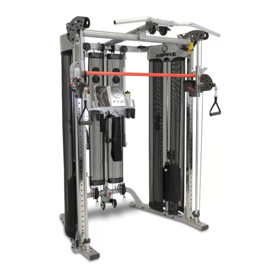
- Page 1 ASSEMBLY & OPERATION MANUAL RECORD SERIAL NUMBER HER...
- Page 2 CONGRATULATIONS… You’ve just taken the first step to a healthier and stronger body. This multi-gym by Inspire offers the key to unlocking your body’s potential. Regular strength training on a multi-gym has been shown to deliver a host of benefits including: increased muscle tone, decreased body fat, improved energy levels, a reduction in stress, and improved cardiac output.
-
Page 3: Table Of Contents
TABLE OF CONTENTS Section Description……………………………………………………. Page Important Safety Instructions………………………………………. Tools Required………………………………………………………………… Parts & Hardware List……………………………………………………. Exploded View …………………………………………………………………. Cable Chart ……………………………………………………………………. Assembly Instructions……………………………………………………. 5-24 Decal Reference……………………………………………………………… Decal Placement……………………………………………………………… Accessories……………………………………………………………………… General Maintenance Information…….…………………………… Maintenance Schedule…….……………………………………………… Limited Warranty…………………………………………………………….. -
Page 4: Important Safety Instructions
• Keep the multi-gym away from walls and clear of any obstructions and furniture. • Stop immediately if you experience shortness of breath, pain, or dizziness during your workout. Inspire strongly recommends consulting your doctor before starting an exercise program. TOOLS REQUIRED FOR ASSEMBLY •... -
Page 5: Parts & Hardware List
Parts & Hardware List Qty Rec'd Qty Rec'd Item Item Parts Description Parts Description Right Base "D" Handle Left Base Slider Adjustment Handle Rear Cross Brace Pull-up Strap Front Upright, Left Ankle Strap Front Upright, Right Add-on Weight, 5 Lb Rear Upright Upper Shroud Mount Bracket, Front Rear Pulley Mount... -
Page 6: Exploded View
FT2 Exploded View PAGE 3 rev 111412... -
Page 7: Cable Chart
CABLE CHART Upper Cable Cable Number 695-500-002 Lower Cable Cable Number 695-500-001 Rear Cable Cable Number 695-500-003 PAGE 4... -
Page 8: Assembly Instructions
ASSEMBLY INSTRUCTIONS PAGE 5... - Page 9 STEP 1 Base 4 - M10*120 Hex Bolts (78) 8 – M10 Flat Washers (97) 4 – M10 Locknuts (98) Attach the Rear Cross Brace (3) to the Right and Left Main Bases (1&2) using 4- M10x120 Hex Bolts (78), 8- M10 washers (97), and 4- M10 Lock Nuts (98). Tighten all the hardware at this time.
- Page 10 STEP 2 Front Uprights 8 - M8*16 Button Head (84) 8 - M8 Flat Washers (100) 2 - M10x80 Socket Head (79) 2 - M10 Flat washer (97) 2 - M10 Locknut (98) 2- M10x90 Hex bolts (80) 4 - M10 Flat washer (97) 2 - M10 locknut (98) A) Attach the Right Front Upright (4R) to the Right Main Base (1) and the Left Front Upright (4L) to the Left Main Base (2), using 8- M8x16 Button Head bolts (84)
- Page 11 STEP 3 Rear Upright 2 - M10*85 Hex Bolts (89) 4 – M10 Curved Washers (99) 2 – M10 Locknuts (98) 1 - M10*80 Hex Bolt (83) 2 – M10 Curved Washers (99) 1 – M10 Locknut (98) A) Attach the Rear Upright (5) + the Rear Pulley Mount (6) to the Rear Cross Brace (3) using 2- M10x85 Hex bolts (89), 4- M10 Curved washers (99), 2- M10 Lock nuts (98) and 1- M10x80 Hex bolt (83), 2- M10 Curved washers (99) and 1- M10 Lock nut (98).
- Page 12 STEP 4 Swivel Pulley Sliders 55 44 2 - M12*85 Hex Bolts (85) 4 – M12 Flat Washers (74) 2 – M12 Locknuts (93) 2-larger ID Slider Rubber Donuts (76) 4 - M6x5 Set screws (107) A) Insert the Linear Bearing Shafts (10) into the collars at the bottom of the Front Uprights (4R & 4L). Attach these with 4-M6x5 Set screws (107) at the bottom of the collars to hold the Linear Bearing Shafts (10) in place.
-
Page 13: Weight Bar
STEP 5 Weight Bar A) Place the Right and Left Sliders (8&9) (from step 4) at the same number position on each Front Upright (4R & 4L). B) Slide a Shock Absorbing Spring (11) over each Linear Bearing Shaft (10) and rest on the Slider (8&9) as shown. - Page 14 STEP 6 Top Beams 2 - M10*95 Hex Bolt (91) 4 - M10 Flat Washers (97) 2 – M10 Locknuts (98) 4 - M10*90 Hex Bolt (80) 2 - M10*75 Hex Bolt (82) 8 - M10 Flat Washers (97) 4 - M10 Flat Washers (97) 4 –...
- Page 15 STEP 7 Top Beam Plate Assemblies 2 – M10*70 Hex Bolt (81) 4 – M10 Flat Washer (97) 2 – M10 Locknut (98) 4 – M10*75 Hex Bolt (82) 8 – M10 Flat Washer (97) 4 – M10 Locknut (98) Note: The Left Top Beam Plate Assembly (18) (as in using the machine with your back to it) has a Yellow Safety Latch preassembled to it.
- Page 16 STEP 8 2 – M12*30 Hex Bolt (88) 2 – M12 Flat Washers (74) 2 – M12 Locknuts (93) Must install these M12 bolts from back to front 2 – M10*25 Hex Bolt (86) 4 – M10 Flat Washers (97) 1 –...
- Page 17 STEP 9 Weight Stacks 1 – M10*120 Hex Bolt (78) 2 – M10 Flat Washers (97) 1 – M10 Locknuts (98) 2 – M10*85 Hex Bolt (89) 4 – M10 Flat Washers (97) 2 – M10 Locknuts (98) 2 – M10*115 Hex Bolt (92) 4 –...
- Page 18 STEP 9 continued E) Attach the 2 Guide Rods (24) to the Right Top Beam (15) using 2- M10x85 Hex bolts (89), 4- M10 Washers (97) and 2- M10 Lock nuts (98), inserted first through the Guide Rods, from inside to outside. Tighten these bolts now. F) Attach a 3-1/2”...
- Page 19 STEP 10 Pulley 8 Pulley 9 Pulley 7 Pulley 10 Pulley 6 Pulley 12 Pulley 4 Pulley 3 Pulley 11 Pulley 13 Pulley 2 Pulley 5 Pulley 1 Upper Cable # 695-500-002 Note: Make sure all cables are run between the retainer pin and the pulley.
- Page 20 STEP 11 Lower Cable Pulley 16 Lower Cable # 695-500-001 Pulley 14 1 - M12 Cable Adjustment Bolt (37) Pulley 15 1 - M12 Flange Nut (45) A) Route the Lower Cable (32) starting with the small swage end without the red tab. Slide cable under Pulley 14 from front to back and under the Weight Stack Riser slots as shown, to Pulley 15, go under and up over floating Pulley 16 (Make sure the tab on the floating pulley bracket is sticking towards the outside of the machine), then down to the...
- Page 21 STEP 12 Rear Cable Pulley 18 Pulley 19 Pulley 17 Note: Make sure all cables Rear Cable # are run between the 695-500-003 retainer pin and the pulley. A) Route the Rear Cable (34) starting with the small swage end without the ball stop. Slide cable under and up behind Pulley 17 from front to back, then over floating Pulley 18 (Make sure the tab on the floating pulley bracket is sticking towards the back of the machine) and down around Pulley 19 as shown.
- Page 22 STEP 13 Guide Cables Plastic Bushing (slotted) Rear Guide Cable (shorter) Side Guide Cable (longer) A) Thread one end of the Side Guide Cable (35) into the threaded insert in the side/bottom of the Right Top Beam (15) just above the side floating pulleys (22) for 5 full turns. B) Thread the other end of the Side Guide Cable (35) into the threaded insert in the Right Main Base (2) next to the pulley.
- Page 23 STEP 14 Shroud Mount Brackets Front Upper Shroud Mount Bracket (59 Make sure the horizontal rib is facing to the outside of the machine. 2 – M6*12 Button Head Bolts (95) 2 – M6 Flat Washers (101) Left Right Bracket Bracket (60) (61)
- Page 24 STEP 15 Flat section towards back of machine. 10 - M6*12 Button Head Bolts (95) 10 - M6 Flat washers (101) 4 - M5*10 Philips Head Screws (96) 4 - M5 Flat Washers (102) Step 15, Weight Shrouds A) Slide one end loop of the Outer Fabric Shroud (70) onto an Upper Shroud Bracket (62) so the seams face towards weights and the flat section of the Upper Shroud Bracket is towards the back of the machine.
- Page 25 D) Slide one end loop of the Inner Wide Fabric Shroud (72) and the Inner Narrow Fabric Shroud (71) onto an Upper Shroud Bracket (62) so the seams face towards weights, the Narrow Fabric Shroud is to the front, and the flat section of the Upper Shroud Bracket is towards the back of the Machine.
- Page 26 STEP 16 Rear Shrouds 2 – M10*80 Hex Bolts (83) 4 – M10 Curved washers (99) 2 – M10 Locknuts (98) Step 16, Rear Shrouds A) Attach the Rear Shroud Brackets (63) to the top and bottom holes in the Rear Upright (5), using 2-M10x80 Hex bolts (83), 4-M10 Curved Washers (99), and 2-M10 Locknuts (98).
- Page 27 STEP 17 Book/Accessory Rack 2 – M10*80 Hex Bolts (83) 4 – M10 Curved Washers (99) 2 – M10 Locknuts (98) 2 – M10*20 Button Head Bolts (94) 4 – M10 Flat Washers (97) 2 – M10 Locknuts (98) A) Attach the Book/Accessory Rack Support (47) to the two holes in the middle of the Rear Upright (5), using 2-M10x80 Hex bolts (83), 4-M10 Curved Washers (99), and 2-M10 Locknuts (98).
-
Page 28: Decal Reference
DECAL REFERENCE PAGE 25... -
Page 29: Decal Placement
DECAL PLACEMENT “FT2” Logo label (50 x 38) “WARNING, PINCH POINT” (∅20) “WARNING, PINCH POINT” (∅20) Weight # labels (1 – 21), included with manual. Silver #’s on black background. (18 x 25) “Patent” Label (50 x 30) “NOTICE” Label “... -
Page 30: Accessories
ACCESSORIES • Exercise Book • Revolving Straight Bar • Revolving EZ Curl Bar • Sports Handle • Exercise Rope • D Strap Handles (2) • Pull Up Strap • Ankle Strap • 5# Add On Weight (2) • Water Bottles (2) MULTI-GYM OPTIONS •... -
Page 31: General Maintenance Information
GENERAL MAINTENANCE INFORMATION • Periodically inspect the cables for splitting, cracking or fraying. Also, watch for bulging or flat areas in the cable. • Immediately replace cables at the first signs of damage or wear. Never use equipment with damaged or worn cables. •... -
Page 32: Maintenance Schedule
MAINTENANCE SCHEDULE HOME ROUTINE ENTRY DATE MAINTENANCE Inspect: Links, Pull Pins, WEEKLY Spring Clips, Swivels, Weight Stack Pins WEEKLY Clean: Upholstery Inspect: Cables and WEEKLY their Fittings Inspect: Tautness of all WEEKLY Shrouds Inspect: Accessory Bars 3 MONTHS and Handles 3 MONTHS Inspect: All Decals Inspect: All Nuts and... -
Page 33: Limited Warranty
This is the only express warranty applicable to Health In Motion’s “Inspire” branded strength products. Health In Motion neither assumes nor authorizes anyone to assume for it any other express warranty.
Need help?
Do you have a question about the FT2 and is the answer not in the manual?
Questions and answers