Table of Contents
Advertisement
Advertisement
Table of Contents

Related Manuals for Avanti SDO-21 TP/BP


Summary of Contents for Avanti SDO-21 TP/BP
- Page 1 - 1 -...
- Page 2 - 2 -...
-
Page 3: Table Of Contents
CONTENTS Important Safety Recommendations ………………………………………..... Warranty Exclusions ………………………………………………………………. Assembly Instructions ………………………………………………………………. Identify Garage Door Type ……………………………………………………………… Identify Installation Method ……………………………………………………………… Assembly ……………………………………………………………………………… Installation Instructions ……………………………………………………………… Header Bracket Mounting ………………………….……………………………... Towing Bracket Mounting ……………………………………………………………… Attaching Drive Rail to Header Bracket ……………………………………………… Mounting Drive Rail Assembly to Ceiling ………………………………………………... -
Page 4: Important Safety Recommendations
IMPORTANT SAFETY RECOMMENDATIONS FAILURE TO COMPLY WITH THE FOLLOWING SAFETY RECOMMENDATIONS MAY RESULT IN SERIOUS PERSONAL INJURY, DEATH AND / OR PROPERTY DAMAGE. 1. PLEASE READ CAREFULLY AND ADHERE TO ALL SAFETY AND INSTALLATION RECOMMENDATIONS The installation of your new Automatic Garage Door Opener (herein after referred to as “AGDO”) must be carried out by a technically qualified or licensed person. -
Page 5: Warranty Exclusions
IMPORTANT SAFETY RECOMMENDATIONS reverse direction when Subsequent to installation and adjustment, the AGDO the garage door must stop and it comes into contact with a 35mm high solid object placed on the floor under the garage door. The correct function of the Safety Obstruction Force System should be checked on a monthly basis. Never use the AGDO unless the garage door is in full view and free from any object which may impede the movement of the garage door such as cars, children and / or adults. -
Page 6: Assembly Instructions
ASSEMBLY INSTRUCTIONS Identify Garage Door Type Identify the garage door type and then select the preferred installation method (Sec.2) and assembly type (Sec.3) that is best suited to the application. Method A Method B Method C Identify Installation Method Method A –... -
Page 7: Assembly
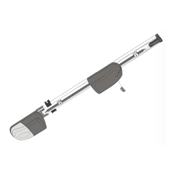
ASSEMBLY INSTRUCTIONS Assembly On a clean smooth surface open the packing carton and expose the AGDO components. (Fig.1) Unfold the Drive Rail and Drive Chain Segments. (Fig.2-A) Use the appropriate number of Drive Rails, Drive Rail Joiners and Chain Segments to suit the preferred Installation Method, A, B or C. - Page 8 ASSEMBLY INSTRUCTIONS (Sectional / Track Type Tip-Up assembly depicted) Fig. 3 Fig. 3A Fig. 3B - 8 -...
-
Page 9: Installation Instructions
INSTALLATION INSTRUCTIONS Header Bracket Mounting Important Note: Before commencing the installation ensure that you have carefully read and understood the Safety Recommendations outlined in pages 4 and 5 of this manual. In particular, ensure that the installation of the garage door complies with the requirements specified in points 3, 4 and 5. -
Page 10: Mounting Drive Rail Assembly To Ceiling
INSTALLATION INSTRUCTIONS Important Note: avoid scratches and potential damage to the AGDO plastic covers by placing the Control Box and Drive Unit on cardboard or foam. Raise the Drive Rail up to the Header Bracket so that the Drive Rail sits in between the ears of the Header Bracket. -
Page 11: Attaching Towing Arms
INSTALLATION INSTRUCTIONS Mount the Drive Rail as per Method A or B. Mount the Control Box either next to the Drive Rail (via the Control Box mounting holes located within the Control Box cover) utilizing the standard cable provided OR on a side wall of the garage (via the 3 hanging mounts located on the base of the Control Box) using the optional cable extension kit. -
Page 12: Connecting To Power Supply
INSTALLATION INSTRUCTIONS Connecting to Power Supply Plug the AGDO into a properly earthed 230 ~ 240 VAC power outlet. Ensure that no excess power cord hangs below the Control Box. Engaging / Disengaging The unique engage / disengage mechanism provides the following features: a. -
Page 13: Settings And Adjustments
SETTINGS AND ADJUSTMENTS Door Travel Adjustment The Drive Rail mounted Limit Prongs provide a 1 to 1 ratio between Limit Prong movement and garage door movement thereby ensuring 100% accuracy and ease of adjustment. Garage door fully open and fully closed positions can be easily adjusted by moving the Limit Prong to the desired location in order to increase or decrease garage door travel. -
Page 14: Adaptive Mode
SETTINGS AND ADJUSTMENTS 12.1 Adaptive (A) Mode Enabling If Manual Mode is your desired selection then skip to Sec.12.2. If Adaptive Mode is already enabled then skip to the next section titled “Functionality”. To enable Adaptive Mode carry out the following procedure; i. -
Page 15: Manual Mode
SETTINGS AND ADJUSTMENTS Testing Close Direction Safety Obstruction Force Value With the garage door in the fully open position - stand in the middle of the garage doorway and just behind the path of the garage door. Ensure that the Close Limit Travel Adjustment (Sec.11) has been set so that bottom of the garage door is resting firmly against the ground. - Page 16 SETTINGS AND ADJUSTMENTS To close out Safety Obstruction Force Adjustment Mode momentarily press “Learn” Button. Note: Mode will close out automatically after 10 mins if not closed out manually beforehand. Safety Obstruction Force Adjustment – Open Direction Hinge open the Lamp Cover (Fig.18-A) to expose the adjustment controls. ...
-
Page 17: Options And Features
OPTIONS AND FEATURES Accessory Connections 6 Output Terminals are provided to support the connection of the most common external accessories. The Output Terminals can be accessed by removing the Courtesy Lamp and Control Box Covers. (Refer Sec.18 for removal and replacement details) Connection Diagrams a. -
Page 18: Battery Back-Up
Replace the Control Box and Courtesy Lamp Covers. Connect the Battery Back-Up power cable to a properly earthed 230 ~ 240VAC power supply. Important Note: The Battery Back-Up system must be genuine Avanti brand Battery Powered AGDO ... -
Page 19: Control Box
An optional Solar Power kit is available. Contact your AGDO dealer for further information. Connect the Solar connection cable to the Control Board terminals “+CH-” Important Note: The Battery Charger must be genuine Avanti brand 17.5 Warning Buzzer ... - Page 20 OPTIONS AND FEATURES iv. remove the Control Box Cover Lock Screw point (Fig.18–B) Note: the Control Box Cover can be removed once the head of the screw is protruding by approx 5mm. v. remove the Control Box Cover by pulling first outwards and then downwards at the finger recess points (Fig.17-B &...
-
Page 21: Courtesy Lamp
OPTIONS AND FEATURES Courtesy Lamp The in built Courtesy Lamp will switch on each time the AGDO is activated and then switch off automatically 90 sec after receiving the last Hand Transmitter or run signal. In order to conserve remaining battery power the Courtesy Light will not function once battery voltage falls below 24V. -
Page 22: Hand Transmitters
OPTIONS AND FEATURES The Courtesy Lamp will triple flash once every 15 seconds once the run time differential exceeds 3 seconds. At this point the garage door should be serviced by a suitably qualified technician. Note: Door Service Monitor function is available only when Adaptive Mode has been selected. Enabling ... -
Page 23: Led Indicator
OPTIONS AND FEATURES LED Indicator The LED Indicator (Fig.18-C) is located under the Courtesy Lamp Cover and serves to indicate the functions as described in the following tables; Green LED – Transformer and Battery Powered AGDO Provides visual indication of functionality sequences as described in the following table; Display Indicator Glow Solid... -
Page 24: Safety Reverse
OPTIONS AND FEATURES Aftermarket 4 Wire Follow Safety Beam manufacturers instructions and connect to the Output Terminals depicted in Fig.13 Important Note: AGDO provides 24VDC output and Normally Open input. Alignment Adjust the Safety Beam module marked “Transmitter” (by turning the mounting bracket) so that it is aimed directly at the lens of the Safety Beam module marked “Receiver”. -
Page 25: Soft Start
OPTIONS AND FEATURES Soft Start When commencing movement from any stationary position the AGDO will slowly ramp up to full speed in order to minimize start-up load on the AGDO and garage door and provide smooth, quiet operation. Soft Stop ... -
Page 26: Wall Switch (Hard Wired)
OPTIONS AND FEATURES Wall Switch – Hard Wired A permanently wired Wall Switch may be connected to the AGDO in a convenient location such as adjacent to a side entry door into the garage. Connection Use a normally open momentary contact type switch (similar to spring loaded front door bell type switch) ... -
Page 27: Troubleshooting Guide
TROUBLESHOOTING GUIDE Reference Symptom Suggested Remedies/Reasons Page Sec. • Check that power chord is plugged-in and turned on • Check power point by plugging-in an alternate appliance • Check that AGDO is engaged to door • AGDO will not function at all •... - Page 28 - 28 - NOTES...
Need help?
Do you have a question about the SDO-21 TP/BP and is the answer not in the manual?
Questions and answers