Table of Contents
Advertisement
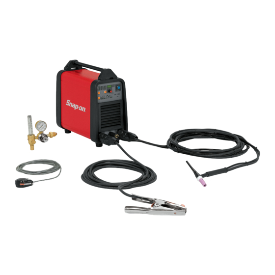
150 A TIG WELDING MACHINE
TIG150i
INTRODUCTION
The TIG150i is a 150A inverter-style AC/DC TIG welder that is used to weld both ferrous
and non-ferrous metals. The inverter technology is a smaller and therefore lighter package
size allows portability when needed or can also be placed onto a cart for traditional use
around the shop. Welding capabilities range from extremely thin up to 1/4" on multiple
passes. The welder features ease-of-use for quick start-up in addition to multiple features
such as upslope, downslope, pulse and frequency adjustment or the most experienced
welder. Applications include automotive repair, collision repair, motorsports, manufacturing,
marine, aviation, agriculture and metal fabrication shops.
032011
Advertisement
Table of Contents

Related Manuals for Snap-On TIG 150i


Summary of Contents for Snap-On TIG 150i
- Page 1 150 A TIG WELDING MACHINE TIG150i INTRODUCTION The TIG150i is a 150A inverter-style AC/DC TIG welder that is used to weld both ferrous and non-ferrous metals. The inverter technology is a smaller and therefore lighter package size allows portability when needed or can also be placed onto a cart for traditional use around the shop.
-
Page 2: Table Of Contents
TABLE OF CONTENTS Introduction ..........................Front Cover Table of Contents ............................1 Safety Information ..........................2-3 Specifications ............................4 Features ..............................5 Description of Equipment ........................6-9 Assembling the Unit/Start-up Guide ......................10 TIG Welding – Introduction ......................... 11-12 DC TIG Welding..........................13 AC TIG Welding ........................ -
Page 3: Safety Information
SAFETY INFORMATION MUST READ INSTRUCTIONS BEFORE USE Arc Welding Read, understand and follow all safety messages and instructions in this manual. Safety messages in DANGER this section ofthe manual contain a signal word with a three-part message and, in some instances, an •... -
Page 4: Safety Information
SAFETY INFORMATION cont’d Risk of Electrical Shock Electrical and Magnetic Fields WARNING WARNING Electrical shock can result when contacting Welding may cause localized Electrical and • • live electrode or internal components Magnetic Fields around cables and power Electrical shock can result from absence of sources •... -
Page 5: Specifications
SPECIFICATIONS By selecting TIG AC welding mode you may weld SPECIFICATIONS aluminum, aluminum alloys, brass and magnesium, while Power Input selecting TIG DC allows you to weld steels, Voltage 208/230 Volts AC stainless steel, iron and copper. This welding machine is a direct and alternating current Phase ... -
Page 6: Features
FEATURES • 150 Amp AC/DC TIG Welder • Pulsed arc for working even on thin sheets, where the heat transferred must be kept to a • TIG weld most metals. minimum. • MMA “Stick Welding” with optional cable • Tunnel design construction allowing an assembly. -
Page 7: Description Of Equipment
DESCRIPTION OF EQUIPMENT The LEDs light alongside the various symbols to display your choice:... - Page 8 DESCRIPTION OF EQUIPMENT cont’d The Pulsed welding feature varies the weld current from the - Procedure selector switch main welding current (Peak Amperage – high heat) and the (Left-hand “down arrow” Key second level of welding or base current (Background This push-button selects the welding procedure (MMA or Amperage –...
- Page 9 DESCRIPTION OF EQUIPMENT cont’d - LED - THERMAL PROTECTION - LED Lights when the operator exceeds the duty cycle or Wave balance in AC welding (balance = 0; Cleaning percentage intermittence admissible for the machine, and = from 1 to 8, flashing; Penetration = from 1 to 8, simultaneously blocks the current output.
- Page 10 DESCRIPTION OF EQUIPMENT cont’d - LED Note: only those LEDs that refer to the chosen welding Slope up. This is the time in which the mode will light; i.e., in continuous TIG welding the LED current, starting from the minimum, representing the pulse frequency, will not light.
-
Page 11: Assembling The Unit/Start-Up Guide
ASSEMBLING THE UNIT/START UP GUIDE INSTALLATION Make sure that the supply voltage is 230 volt and a minimum of 30 amp service. When mounting a plug, make sure it has For detailed machine start up see an adequate capacity, and that the "yellow/green “SETTING UP YOUR NEW conductor"... -
Page 12: Tig Welding - Introduction
TIG WELDING - INTRODUCTION TIG WELDING – GENERAL By selecting the TIG AC welding mode you may weld aluminum, aluminum alloys, brass and magnesium, while selecting TIG DC allows you to weld steels, stainless steel, iron and copper. 1. Connect the earth (work) cable connector to the positive pole (+) (AC) of the welding machine, and the clamp to the work piece as close as possible to the welding point, making sure there is good... -
Page 13: Tig Welding – Introduction
TIG WELDING – INTRODUCTION cont’d 3. The flow of inert gas must be set to a value of 20-25 4. The diameter of the ceramic nozzle must be 4 to 6 times CFH. If you are using gas-lens type accessories, the gas the diameter of the electrode throughput may be reduced. -
Page 14: Dc Tig Welding
DC TIG WELDING TIG Welding DC Basic Setup With High Frequency Start • Using the On/Off Switch • Push the procedure selector switch (Left Hand Down Arrow). This push-button selects the welding procedure (MMA or TIG). When selected, one of the following LEDs lights: , or Push the button until the TIG DC LED lights... -
Page 15: Ac Tig Welding
AC TIG WELDING TIG AC Welding Mode Basic Setup Push the – Selector (Right Arrow) until the – LED With High Frequency Start • wave balance display lights. Using On/Off Button • - LED Push the procedure selector switch (Left Hand Down Wave balance in AC welding. -
Page 16: Ac Tig Welding
AC TIG WELDING cont’d Turn the -Knob watching the - Display. Push the – Selector (Right Arrow) until the – LED slope down display lights. Set the slope up to “0” seconds. - LED Slope down. This is the time in which the current reaches the minimum and the arc shuts off. -
Page 17: Optional Foot/Remote Amperage Control
OPTIONAL FOOT PEDAL/ REMOTE AMPERAGE CONTROL How to Setup the Optional Variable Amperage Foot Pedal or Activate the foot pedal or RAD to the maximum (pedal or Remote Finger Amp Control (RAD). slider fully depressed) position. While holding down the pedal to maximum, Using High Frequency Start •... -
Page 18: Stick Arc Welding
STICK ARC WELDING MMA WELDING (MANUAL METAL ARC OR STICK WELDING) DC (10-130 Amps) - Make sure that the switch is in position 0, or “off” position then connect the welding cables, observing the polarity required by the manufacturer of the electrodes you will be using; also connect the clamp of the ground cable to the work piece, as close to the weld as possible, making sure that there is good electrical contact. -
Page 19: Troubleshooting/Maintenance
TROUBLESHOOTING/MAINTENANCE DESCRIPTION OF PROTECTIVE DEVICES TIG WELDER MAINTENANCE Thermal protection Any maintenance operation must be carried out by qualified This machine is protected by a temperature probe, which personnel. prevents the machine from operating if the allowable temperatures are exceeded. Under these conditions the fan keeps running and the LED lights. -
Page 20: Parts List
REPLACEMENT PARTS – PARTS LIST WHEN ORDERING SPARE PARTS PLEASE STATE THE MODEL NUMBER AND SERIAL NUMBER AND PART NUMBER NEEDED. -
Page 21: Replacement Parts
REPLACEMENT PARTS – STANDARD AND OPTIONAL ACCESSORIES... -
Page 22: Wiring Diagram
WIRING DIAGRAM... -
Page 23: Warranty/Service And Repair
Snap-on Tools Company Limited Two (2) Year Warranty Snap-on Tools Company (the “Seller") warrants only to original purchasers who use the Equipment in their business that under normal use, care and service, the Equipment (except as otherwise provided herein) shall be free from defects in material and workmanship for two years from the date of original invoice.
Need help?
Do you have a question about the TIG 150i and is the answer not in the manual?
Questions and answers