Table of Contents
Advertisement
Advertisement
Table of Contents

Related Manuals for Motorola AP-7532


Summary of Contents for Motorola AP-7532
- Page 1 AP-7532 Access Point INSTALLATION GUIDE...
- Page 2 AP-7532 Access Point MOTOROLA SOLUTIONS and the Stylized M Logo are registered in the US Patent & Trademark Office. © Motorola Solutions, Inc. 2014. All rights reserved.
-
Page 3: Table Of Contents
1.3 Site Preparation ......... . . 6 1.4 AP-7532 Package Contents ........6 1.4.1 Features . - Page 4 5.13 Turkish WEEE Statement of Compliance ..... . 42 6.0 Motorola Solutions Support Center ......43...
-
Page 5: Introduction
Point, an Adaptive Access Point, or a Virtual Controller. If new to Motorola Solutions Access Point technology, refer to the WiNG Access Point System Reference Guide to familiarize yourself with Access Point technology and the feature set supported by the WiNG operating system. -
Page 6: Warnings
• Verify cable lengths are within the maximum allowable distances for optimal signal transmission. 1.4 AP-7532 Package Contents An AP-7532 Access Point is available in both external antenna (AP-7532) and internal antenna (AP-7532I) configurations. An AP-7532 ships with the following: •... -
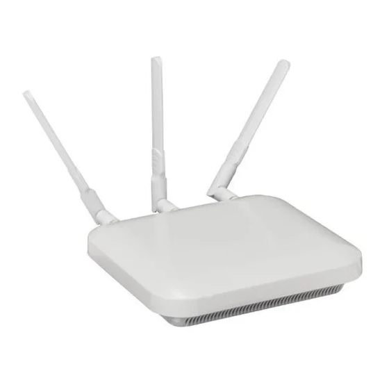
Page 7: Ap-7532 Antennas
Installation Guide 1.5 AP-7532 Antennas An AP-7532 external antenna Access Point supports the following dual band antenna options: Part Number Antenna Type 2.4 GHZ Gain (dBi) 5 GHZ Gain (dBi) Impedance (Ohms) ML-2452-APA2-01 Dipole 3.17 ML-2452-HPA5-036 Dipole ML-2452-APAG2A1-01 Dipole ML-2452-PNA5-01R... -
Page 8: Hardware Installation
Hardware Installation 2.1 Installation Instructions An AP-7532 Access Point mounts either on a wall (with M 3.5 x 0.6 x 23 MM pan head screws and mounting bracket- or equivalent) or on a suspended ceiling T-bar. To prepare for the installation: 1. -
Page 9: Access Point Placement
2.4 Power Injector System An AP-7532 Access Point can receive power via an Ethernet cable connected to the GE1/POE (LAN) port. When users purchase a WLAN solution, they often need to place Access Points in obscure locations. In the past, a dedicated power source was required for each Access Point in addition to the Ethernet infrastructure. - Page 10 AP-7532 Access Point The Motorola Access Point Power Supply (Part No. PWRS-14000-54R) is not included with the Access Point and is orderable separately as an accessory. If the Access Point is provided both POE power and PWRS-14000-54R power concurrently, the Access Point will source power from the PWRS-14000-54R supply only. Disconnecting the AC power from the PWRS-14000-54R causes the Access Point to re-boot before sourcing power from the POE power injector.
-
Page 11: Wall Mount Instructions
2.5 Wall Mount Instructions A wall mount deployment requires hanging the AP-7532 Access Point with the provided mounting bracket and two screws. The AP-7532 can be mounted on to any plaster, wood or cement wall surface using the provided mounting bracket. -
Page 12: Wall Mount Procedure - New Installation
AP-7532 Access Point 2.5.1 Wall Mount Procedure - New Installation This section describes a new AP-7532 installation with no previous Access Point existing on the intended wall surface. 1. Place the mounting bracket against the wall. 2. Mark the screw hole locations depending on the intended deployment orientation of the unit. -
Page 13: Wall Mount Procedure - Existing Access Point Replacement
2.5.2 Wall Mount Procedure - Existing Access Point Replacement An existing AP-7131 or AP-7131N Series Access Point installed on a wall can be replaced by an AP-7532. Simply remove the existing AP-7131 or AP-7131N and install the new provided mounting bracket for AP-7532 directly to... -
Page 14: Suspended Ceiling T-Bar Mount Installation
2.6 Suspended Ceiling T-Bar Mount Instructions Ceiling mount requires holding the AP-7532 up against a T-bar of a suspended ceiling grid and twisting the unit on to the T-bar. If deploying the AP-7532 on a sculpted ceiling T-Bar, the Access Point mounting kit (Part No. - Page 15 Do not actually connect to the power source until the cabling portion of the installation is complete. 3. Verify the unit has power by observing the LEDs. For more information on AP-7532 LED behavior, see Indicators on page 17 4. Align the bottom of the ceiling T-bar with the back of the Access Point.
- Page 16 AP-7532 Access Point 8. Rotate the Access Point chassis 45 degrees counter-clockwise. The clips click as they fasten to the T-bar. 9. The Access Point is ready to configure.
-
Page 17: Led Indicators
Installation Guide 2.7 LED Indicators The AP-7532 LED activity indicators are located on the front of the housing and are visible through the enclosure. - Page 18 AP-7532 Access Point The LEDs provide a status display indicating error conditions, transmission, and network activity for the 5 GHz 802.11ac (amber) radio and the 2.4 GHz 802.11n (green) radio. Task 5 GHz Activity LED (Amber) 2.4 GHz Activity LED (Green)
-
Page 19: Basic Access Point Configuration
Installation Guide Basic Access Point Configuration Once the AP-7532 is installed and powered on, complete the following steps to get the Access Point up and running and access management functions: 1. The Access Point’s IP address is optimally provided using DHCP. A zero config IP address can also be derived if DHCP resources are unavailable. - Page 20 AP-7532 Access Point 3. Enter the default username admin in the Username field. 4. Enter the default password motorola in the Password field. 5. Click the Login button to load the management interface. When logging in for the first time, you’re prompted to change the NOTE password to enhance device security in subsequent logins.
- Page 21 Installation Guide The Initial Setup Wizard displays the same pages and content for each NOTE Access Point type supported. The only difference being the number of radios configurable by Access Point type, as an AP7131 Access Point can support up to three radios, AP6522, AP6532, AP6562, AP8132 and AP7161 Access Points support two radios and AP6511 and AP6521 Access Points support a single radio.
- Page 22 9. The Typical Setup Wizard displays the Access Point Settings screen to define the Access Point's Standalone versus Virtual Controller AP functionality. This screen also enables selection of the country of operation for the Access Point. The professional installer should refer to the Motorola Solutions WiNG NOTE Access Point System Reference Guide available at https://portal.motorolasolutions.com/Support/US-EN/Wireless+Networks...
- Page 23 UI to connect to the Access Point, provision its configuration and administrate the Access Point’s configuration. If designating the Access Point as a Standalone AP, Motorola Solutions NOTE recommends the Access Point’s UI be used exclusively to define its device configuration, and not the CLI.
- Page 24 AP-7532 Access Point 13. The Typical Setup Wizard displays the Network Topology screen to define how the Access Point handles network traffic. 14. Select an Access Point Mode from the available options. • Router Mode -In Router Mode, the Access Point routes traffic between the local network (LAN) and the Internet or external network (WAN).
- Page 25 Installation Guide 15. Select Next. The Typical Setup Wizard displays the LAN Configuration screen to set the Access Point's LAN interface configuration. 16. Set the following DHCP and Static IP Address/Subnet information for the LAN interface: • Use DHCP - Select the checkbox to enable an automatic network address configuration using the Access Point’s DHCP server.
- Page 26 AP-7532 Access Point • DNS Forwarding - Select this option to allow a DNS server to translate domain names into IP addresses. If this option is not selected, a primary and secondary DNS resource must be specified. DNS forwarding is useful when a request for a domain name is made but the DNS server, responsible for converting the name into its corresponding IP address, cannot locate the matching IP address.
- Page 27 Installation Guide 19. Select Next. The Typical Setup Wizard displays the RADIUS Server Configuration screen if required. Otherwise, the Typical Setup Wizard displays the Summary and Commit screen. 20. Use the Radius Server Configuration screen to configure the users for the onboard RADIUS server. Use the screen to add, modify and remove RADIUS users.
- Page 28 AP-7532 Access Point 21. Select Add User to display the dialog to enter user information to add to the RADIUS server user database. 22. Enter the following user information: • Username - Provide a user name used to authenticate the user.
- Page 29 Installation Guide 28. Select Next. The Typical Setup Wizard displays the Summary and Commit screen to summarize the screens (pages) and settings updated using the Typical Setup Wizard. No user intervention or additional settings are required. Its an additional means of validating the Access Point’s updated configuration before it’s deployed.
-
Page 30: Ap-7532 Access Point Specifications
AP-7532 Access Point AP-7532 Access Point Specifications 4.1 Electrical Characteristics An AP-7532 Access Point has the following electrical characteristics: Operating Current & 12VDC, 1.25A (AUX input voltage) Voltage 12VDC PWRS-14000-54R power supply 48VDC, 0.375A (POE) 802.3at AP-PSBIAS-2P3-ATR Power Injector 4.2 Physical Characteristics... -
Page 31: Radio Characteristics
Installation Guide 4.3 Radio Characteristics The AP-7532 Access Point has the following radio characteristics: Data Rates Supported 802.11b/g: 1,2,5.5,11,6,9,12,18,24,36,48 and 54 Mbps 802.11a: 6,9,12,18,24,36,48, and 54 Mbps 802.11n: MCS 0-23 up to 450 Mbps 802.11ac: MCS 0-9 up to 1.3 Gbps... -
Page 32: Regulatory Information
This device is approved under Motorola Solutions, Inc. This guide applies to the following Model Numbers: AP-7532, AP-7532I. All Motorola Solutions devices are designed to be compliant with rules and regulations in locations they are sold and will be labeled as required. -
Page 33: Country Selection
Installation Guide 5.2.1 Country Selection Select only the country in which you are using the device. Any other selection will make the operation of this device illegal. Some Access Points are specifically designed to operate in certain countries (Example; -US for the United States, -EU for the European Union). -
Page 34: Health And Safety Recommendations
AP-7532 Access Point 5.3 Health and Safety Recommendations Ergonomic Recommendations Caution: In order to avoid or minimize the potential risk of ergonomic injury follow the recommendations below. Consult with your local Health & Safety Manager to ensure that you are adhering to your company's safety programs to prevent employee injury. -
Page 35: Warnings For The Use Of Wireless Devices
Installation Guide Safety on the Road Do not take notes or use the device while driving. Jotting down a "to do" list or flipping through your address book takes attention away from your primary responsibility, driving safely. When driving a car, driving is your first responsibility - Give full attention to driving. Check the laws and regulations on the use of wireless devices in the areas where you drive. -
Page 36: Rf Exposure Guidelines
The device complies with internationally recognized standards covering human exposure to electromagnetic fields from radio devices. For information on “International” human exposure to electromagnetic fields refer to the Motorola Solutions Declaration of Conformity (DoC) at: http://www.motorolasolutions.com/doc For further information on the safety of RF energy from wireless devices - see http://responsibility.motorolasolutions.com/index.php/downloads/... -
Page 37: Power Supply
This device must be powered from a 802.3af or 802.3at compliant power source which has been certified by the appropriate agencies, or by a Motorola approved UL LISTED ITE (IEC/EN 60950-1, LPS/SELV) power supply with electrical ratings: Output 12 Vdc, min 1.25 A or 48 Vdc min 0.375 A (POE), with a recommended ambient temperature greater than 40 degrees C. -
Page 38: Ce Marking And European Economic Area (Eea)
This radio transmitter (AP-7532, AP-7532I) has been approved by Industry Canada to operate with the antenna types listed below and having a maximum gain allowable and the impedance required for each type of antenna. -
Page 39: Statement Of Compliance
Brazil Declarações Regulamentares para AP-7532 - Brasil Nota: A marca de certificação se aplica ao Transceptor, modelo AP-7532. Este equipamento opera em caráter secundário, isto é, não tem direito a proteção contra interferência prejudicial, mesmo de estações do mesmo tipo, e não pode causar interferência a sistemas operando em caráter primário. - Page 40 AP-7532 Access Point Chile Este equipo cumple con la Resolución No 403 de 2008, de la Subsecretaria de telecomunicaciones, relativa a radiaciones electromagnéticas. China Mexico Restrict Frequency Range to: 2.450 – 2.4835 GHz. S. Korea Taiwan 在 5.25-5.35 秭赫頻帶內操作之無線資訊傳輸設備,限於室內使用 Thailand...
-
Page 41: Waste Electrical And Electronic Equipment (Weee)
Installation Guide 5.12 Waste Electrical and Electronic Equipment (WEEE) English: For EU Customers: All products at the end of their life must be returned to Motorola Solutions for recycling. For information on how to return product, please go to: http://www.motorolasolutions.com/recycling/weee. -
Page 42: Turkish Weee Statement Of Compliance
AP-7532 Access Point Dansk: Til kunder i EU: Alle produkter skal returneres til Motorola Solutions til recirkulering, når de er udtjent. Læs oplysningerne om returnering af produkter på: http://www.motorolasolutions.com/recycling/weee. Ελληνικά: Για πελάτες στην Ε.Ε.: Όλα τα προϊόντα, στο τέλος της διάρκειας ζωής τους, πρέπει να επιστρέφονται... -
Page 43: Motorola Solutions Support Center
• Model number or product name • Software type and version number Motorola Solutions responds to calls by e-mail, telephone, or fax within the time limits set forth in support agreements. If you purchased your product from a Motorola Solutions business partner, contact that business partner for support. -
Page 44: Ap-7532 Access Point China Rohs Compliance
(Plastic and Polymeric Parts) 光学和光学组件 (Optics and Optical Components) 电池 (Batteries) O: 表示该有毒有害物质在该部件所有均质材料中的含量均在 SJ/T11363-2006 标准规定的限量要求以 下。 X: 表示该有毒有害物质至少在该部件的某一均质材料中的含量超出 SJ/T11363-2006 标准规定的限量 要求。 对销售之日的所售产品,本表表示,公司供应链的电子信息产品可能包含这些物质。注意:在所售产品 中可能会也可能不会含有所有所列的部件。 This table was created to comply with China RoHS requirements for Motorola Solutions‘ AP-7532 and AP-7532I Access Points. - Page 45 Installation Guide...
- Page 46 AP-7532 Access Point...
- Page 47 Installation Guide...
- Page 48 Schaumburg, IL 60196-1078, U.S.A. http://www.motorolasolutions.com MOTOROLA, MOTO, MOTOROLA SOLUTIONS and the Stylized M Logo are trademarks or registered trademarks of Motorola Trademark Holdings, LLC and are used under license. All other trademarks are the property of their respective owners. © 2014 Motorola Solutions, Inc. All Rights Reserved.