Table of Contents
Advertisement
Advertisement
Table of Contents

Related Manuals for Sindoh A610 Series


Summary of Contents for Sindoh A610 Series
-
Page 1: Service Manual
2014-01-22 Confidential SERVICE MANUAL A610/A611 SER. -
Page 2: Table Of Contents
A610/A611 SER. LASER PRINTER FIELD SERVICE MANUAL Specifications ...........................1 Main Body ........................1 Main Body Components....................1 Main Body Specfications ...................5 Paper Specificaton ....................7 Toner Specification ....................8 Option Paper Feed Unit ....................9 Option Feeder Components ..................9 Installation ..........................12 Environment, Unpacking and Components ..............12 Option Tray ........................13 Image Cartridge ......................15 Cable Connection ......................16... - Page 3 Drum Cartridge and Toner Cartridge Drive .............33 Drum Cartridge and Toner Cartridge Voltage ............34 Drum Cartridge and Toner Cartridge Replacement ..........35 Paper Feed ........................36 Main Tray ........................36 MPT (Multipurpose Tray) ..................50 Duplex Unit Components ..................53 Resist Unit .......................56 Image Fusing ........................59 Overview .........................59 Output Unit ........................61 Output Unit Components ..................62...
- Page 4 Cooling Fan ........................117 Paper Feed ........................119 Separating Main Feeding Roller ................119 Manual Tray (MPT) ....................123 Separating Upper Body A'ssy of Pick Roll ............125 Disassembling Optional Tray Unit................ 127 Resist Guide A’ssy ....................143 Removing the Resist Roller ................. 144 Output Unit ......................
-
Page 5: Specifications
Main Body Main Body Components (A610DN) Model Type Emulation Civil A610SER SDAPL,PCL5e/6,PS3 A610DN SDAPL (Sindoh Advanced Print Language) – GDI Front Name Remark Tray 1 250 Sheets (75 g/m²) Tray 2 (Optional Tray) 250 Sheets (75 g/m²) Multipurpose Tray (MPT) - Page 6 Back Name Remark Power Cord Connector Power Button USB Port Connector Wi-Fi Connector Ethernet Connector Back Cover Duplex Tray Capacity 1. Basic Configuration: Tray 1 (250 Sheets) + MPT (50 Sheets) 2. Basic Configuration + 2 Optional Trays (250 Sheets)
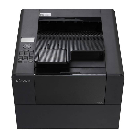
- Page 7 Main Body Components (A611DN) Model Type Emulation Civil A611SER SDAPL,PCL5e/6,PS3 A611DN SDAPL(Sindoh Advanced Print Language) – GDI Front Name Remark Tray 1 500 Sheets (75 g/m²) Tray 2 (Optional Tray) 500 Sheets (75 g/m²) Multipurpose Tray (MPT) Front Cover Control Panel...
- Page 8 Back Name Remark Power Cord Connector Power Button USB Port Connector Wi-Fi Connector Ethernet Connector Back Cover Duplex Tray Capacity 1. Basic Configuration: Tray 1 (500 Sheets) + MPT (50 Sheets) 2. Basic Configuration + 2 Optional Trays (500 Sheets)
-
Page 9: Main Body Specfications
Main Body Specifications (A610DN) Category A610 Model Printing Speed (A4) 40ppm Page Printing Speed Under 9 Seconds Resolution (dpi) 600/1200 dpi Tray Capacity 250 Sheets Paper Size A5 ~ Legal MPT Capacity 50 Sheets Output Capacity 250 Sheets Duplex Option 250 Sheet Tray Memory 256MB... - Page 10 Main Body Specification (A611/A616DN) Category A611 model Printing Speed (A4) 47ppm Page Printing Under 9 Seconds Speed Resolution (dpi) 1200 dpi Tray Capacity 500 Sheets Paper Size A5 ~ Legal MPT Capacity 50 Sheets Output Capacity 250 Sheets Duplex Option 250 Sheet Tray Memory 512MB...
-
Page 11: Paper Specificaton
Paper Specification Feeder Unit By Paper Type Paper Size Weight Standard: 250 Sheets Main Tray A4, A5, JIS B5, Folio, Letter, Legal, 60~120 g/m² Thick: Up to set height (A610) Executive, Statement (16~32lb) (Marked by Label) Standard: 500 Sheets Main Tray A4, A5, JIS B5, Folio, Letter, Legal, 60~163 g/m²... -
Page 12: Toner Specification
Toner Specification Life Item Model Enclosed Toner A610/A611DN 3K/6K/13K Cartridge Drum Unit 45K (Consecutive printing) 30K (3page/job) 18K (1page/Job) Conditions: 1. Life specified above is based on A4 and 5% charts. 2. Standard temperature and humidity 3. Life may vary according to environment and printing conditions. -
Page 13: Option Paper Feed Unit
250 Sheet Option Paper Feed Unit Feeder Components Pickup & Feed roll A’ssy 1. Pickup roll A’ssy Feeder -D-roller, 2 idler 1. Friction Pad A’ssy -2 Segment gear clutch A’ssy 2. Center Align System -DC solenoid (1 EA) 3. Incline plate (1 EA) + Incline spring (2 2. -
Page 14: Paper Feed Unit
500 Sheet Option Paper Feed Unit Optional Feed General View of Optional Tray Feed Unit 1. DC Motor 1EA 2. Pick Tire 2EA (EPDM) 3. Gear Arm A’ssy 1EA 4. Gear Housing A’ssy 1EA 5. Gear Arm Pivot A’ssy 1EA 6. - Page 15 Tray Specification Category Description Increase Tray’s capacity Function Speed 45PPM / 40PPM (A4 SEF, KARA-S 45PPM, KARA 40PPM) Feeder Capacity 500 Sheets (75gsm) /1 Paper Min. A5 ~ Max. Legal(Xerographic OR Business paper) Paper Weight 16 ~ 90 lb(60 ~ 163gsm) paper Dimension (H/W/D) 130.3 mm / 383 mm / 387 mm Weight...
-
Page 16: Installation
Installation Installing Conditions Environment The printer must be installed at following places. Good ventilation and flat surface No obstacles within 8cm from printer’s right side for cooling fan to operate properly No direct sunlight exposure and dustless and clean place ... - Page 17 CORE (For network cable) 2. Enclosed cartridge 3. Power cable 4. USB cable 5. Quick installation manual 6. Driver CD (Include User manual) 7. Warranty sheet 1. Tray1 (Default:250 sheet) 8. CORE(Used for network cable) Model name:28A2029-0A0 Installing Optional Feeder (250 Sheets & 500 Sheets) Installation Please proceed with the followings before installing the optional feeder after the printer installation.
- Page 18 3. Hold both edges of support and place it on the printer placing location. 4. Re-install the feeder. Push it in until it completely attaches. 5. Hold both handles on the bottom sides, lift it up and place it on the placing location. Align the tab, narrow hole and connector on the top of the feeder exactly with the bottom of printer.
-
Page 19: Image Cartridge
Image Cartridge Installation 1. Open the top front cover. Hold the handles of the cartridge and accurately align both front hooks (arrow stickers) with both guide grooves of the printer (arrow stickers). 3. Push in the cartridge until you hear a click inside the printer. 4. - Page 20 Connecting Cables 1. Check if power has been switched off from the printer, computer and other connected devices. 2. *Connect the USB cable. * Network Connection – Connect the enclosed CORE to the cable before connecting the network cable. *Wi-Fi Connection (Wi-Fi Module (WN400) option) Recognized automatically without driver installation ※...
-
Page 21: Maintenance
Maintenance Preventive Maintenance User Replaceable Items Category Model Item Life Fuser unit 120K For A610/A611 Transfer roller 120K A610/A611 MPT separation pad A610/A615 Pickup roller & separation pad 120K A611/A616 Feeder Accufeed roller 120K Service life of this device is 400,000 sheets (A610)/ 600,000 sheets (A611) in years. Consumable parts have direct effect on burns and machine operation. -
Page 22: Detailed Description
Detailed Description IMAGE PROCESS Charging Voltage of -1540V is applied to charging roller from HVPS and the drum surface is charged with approximately -900V. Exposure... - Page 23 Laser scanning is performed to the image printing area and the surface electric potential of scanned area drops to about -300V to form ‘Latent Image’. Development Images are formed on the drum surface by attaching the charging toner with approximately -550V via development roller and Doctor blade on the latent image area formed by laser from exposure stage.
- Page 24 Images are formed by toner transfer on the drum surface from the Development stage and when paper passes, +2000V of electricity applied to the transfer roller pulls the image forming toner particles on drum surface to form unsettled images on the paper. Cleaning Remaining toner on the drum surface after transferred to paper gets trimmed by cleaning blade before getting into charging roller and gets collected in the used toner collecting...
-
Page 25: Machine Overview
Machine Overview Machine Components 1. Output Roller 12. Multipurpose Tray Feed Roller 2. LSU 13. Multipurpose Tray Friction Pad 3. Polygon Mirror Motor 14. Tray 1 Feed Roller 4. Cleaning Blade 15. Tray 1 Friction Pad 5. Charging Roller 16. Tray 1 Base Plate 6. -
Page 26: Paper Path
Paper Path 1. Output Bin 2. Multipurpose Tray 3. Main Feeder 4. Optional Feed Unit 5. Duplex Unit... -
Page 27: Electrical Components
Electrical Components Symbol Name Function Motor Operates main body Main Rotates polygon mirror motor Polygon mirror Cools heat around fuser unit Exhaust fan Switch Supplies power to the machine. If this is turned off, no power will be supplied to the machine Power (Located on the bottom right on the back of the machine) - Page 28 Symbol Name Function When there’s no paper on the tray, notification will Feeder Empty be transferred to the CPU When there’s no paper on the tray, notification Multipurpose tray empty will be transferred to the CPU Detects paper jam Paper Feed Symbol Name Function...
-
Page 29: Main Driving Gear Unit
Drive Chain 1. Main Motor 2. Multipurpose Tray Feeding Solenoid 3. Electromagnetic Feeding Clutch in Tray Main Driving Gear Units Main Driving Gear Unit Components The machine has one main motor and the rotation of this motor is delivered to the train of gears composed with various gears to operate developer/drum, manual feeder, fusing unit, duplex unit, resist roller and pickup roller. - Page 30 Installing/Removing Image Cartridge 1. Front cover open When machine’s front door is opened, the link connected to the front door moves in the direction of 1. Lever no.2 moves consecutively by the moving link, and the Oldham lever and dog-bone lever each pull the coupler, disconnecting from the cartridge. 2, Front cover closed...
- Page 31 When the front door of the machine is closed, Link 1 connected to the front door moves in the direction of 1. Lever no.2 moves consecutively by the moving link, and the Oldham lever and dog-bone lever each push the coupler, connecting to the cartridge. Removing Fusing Paper Jam 1.
-
Page 32: Laser Unit
Laser Unit Structure and Optical System Path A : Laser Diode Unit F : Synchro Reflection Mirror B : Collimator Lens Unit G : Synchro Detect Sensor C : Cylindrical Lens H : #2 F-theta lens D : Polygon Mirror Motor I : Reflection Mirror E : #1 F-theta lens J : OPC Drum... - Page 33 Reflection Mirror: Alters laser’s direction Synchro Detect Sensor: Determines the scan starting position Laser Safety CDRH (Center for Devices and Radiological Health) prohibits laser unit repairing on a field. A laser unit can only be repaired in a factory or necessary places. A laser unit can be replaced with qualified customer service technician and internal parts of laser unit cannot be replaced on a field.
-
Page 34: Image Cartridge
Image Cartridge Overview Drum Cartridge Toner Cartridge Image cartridge is composed with drum cartridge and toner cartridge as shown above and can be separated. Drum cartridge does not have a separate chip, but toner cartridge has a separate information chip to store toner counter and manufacturer information. The machine refers to the information on the chip to determine toner replacing period and auto toner counter reset. - Page 35 Drum Cartridge Component Charging Cleaner Roll Charging Roll Used Toner Case Drum cartridge consists of a drum, charging roller, cleaning blade, and a compartment for collecting used toner. Toner Cartridge Components Development Roll A toner cartridge consists of a Development roller, Add roller and a Doctor blade as shown above and has a Paddle roller carrying toner to add roller.
- Page 36 Drum Cartridge Drive Drum cartridge’s drum rotates by delivering the motor’s driving force generated by the rotation of main motor (A) to drum (C) via drum driving gear (B).. Toner Cartridge Operation When the driving force of main motor (A) is delivered to development coupler driving gear (B), the Oldham type coupler (C) rotates.
- Page 37 Drum Cartridge’s Applied Voltage Charged voltage of -1540V is applied to the charging roller (I) contacting Drum (C). The charged voltage is applied to the cleaning blade BKT (F) from HVPS via charging voltage applied spring (D) and charging voltage applied plate (E), and this applied voltage is delivered to charging roller again via charging roller spring (G) and conductive roller bushing (H).
- Page 38 Three types of voltages are applied to a toner cartridge. The necessary voltage is applied to development roller via development applied voltage spring (A) and development roller plate (D), and to add roller via add voltage applied spring (B) and add roller plate (E), and to doctor blade via DB voltage applied spring (C) and DB plate (F).
-
Page 39: Paper Feed
Paper Feed (A610DN) Overview The printer is installed with a 250 sheets of A4 cassette Tray with 75gsm as base and a bypass tray as the base and 250 sheet feeding unit can be added optionally. A friction pad method is used as paper separating method for main tray and a paper detecting sensor is mounted to determine paper presence, but a separate auto paper size detecting sensor is not installed, which allows the printer to detect the paper size by on-off timing of Resist sensor. - Page 40 2) Right side fence 5) Separation friction pad 1) Base plate 6) Base pad 4) Rear fence expanding lever 2) Right side fence 3) Rear fence Main Body’s Pickup Part Components and Driving Mechanism The main tray consists of the following 4 components. Role of each component is specified below.
- Page 41 Main Feeder Drive When you open the cassette tray, load paper and close it again, the base plate is unlocked, lifting paper towards the pickup roller. Feeder is now ready to feed paper. When the feed signal is entered in the main body, the electromagnetic clutch is activated, the pickup roller rotates and the topmost paper is pick up and moved towards the main body.
- Page 42 Side Fence/Rear Fence Controls Right Side Fence Lever Paper Load Limit Hold right side fence lever and right side fence to move the side fence. Load paper up to the paper load limit on the side fence. Reusable paper can be categorized as Special Paper because of its curl.
- Page 43 No Paper Detection End Detection Flag Base Plate Slit When the cassette tray becomes empty, the paper detection sensor flag drops to the slit in the base plate. The sensor flag blocks the path of the light from the transmitter to the receiver, altering the sensor output value.
- Page 44 Paper Size Detection A610 does not have a Paper Size Detection Sensor. Select the size in the driver. Paper Feed (A611DN) Overview KARA-S and the 500 sheet option both use Accufeed method to feed paper. 500 option and KARA-S cannot share the same feeding tray. KARA-S is equipped with a 75gsm cassette tray with a capacity of 500 A4 sheets, and with the 500 option you can install two 500-sheet feeders in addition.
- Page 45 1) Separation 2) Left Side Fence (5EA) 4) Last-page Separation Friction Pad (2EA) 2) Right Side Fence 3) Rear Fence 펜스 Pickup Part Components and Mechanism The pickup part consists of the following 3 components. Role of each component is as follows.
- Page 46 Mechanism for Opening/Closing Tray For the 500 option, when the main tray of KARA-S is opened and paper is loaded, the Bell- crank spring [2] pulls the Bell-crank spring arm [4]. The shaft pin [3] connected supports Accufeed arm A’ssy [1] and holds it in place. When the loaded tray is closed, the structure of the tray [5] presses the Bell-crank spring arm [4] and no longer supported by the shaft pin [3].
- Page 47 If the pickup roller has begun operating by paper slip or other feeding condition but failed to feed paper into the transfer roller, the pickup roller picks up paper twice more. When the tray has fed all the paper inside, the paper detection sensor operates and displays a Paper Low message.
- Page 48 Rear Fence Lever Adjust the rear fence lever by holding and moving the fence. To load paper, hold the rear fence lever and push it back as far as possible, align the front part of paper to the separation dam, then hold the lever again and move it to fit the edge of the paper. Hold the rear fence in place.
- Page 49 Paper Detection Paper Detection FEELER SENSOR 1 SENSOR 2 When the cassette tray becomes empty, the paper detection sensor flag drops to the slit in the base plate. The sensor flag blocks the path of the light from the transmitter to the receiver, altering the sensor output value.
- Page 50 Paper Size Detection Adjust the end fence to fit the bottom edge of paper. The detection finger connected to the paper size detection sensor (Switch sensor, 3EA) enters the hole in the end fence for paper detection. If the finger can enter the hole, the sensor detects “0”. If the finger cannot enter the hole, the sensor detects “1”.
-
Page 51: Mpt (Multipurpose Tray)
MPT (Multipurpose Tray) Overview This printer is equipped with a multipurpose tray (MPT) with a capacity of 50 A4 sheets (75gsm) as default. MPT, like the main tray, uses friction pads to separate paper. A paper detection sensor is installed to detect paper status in the MPT. Because the MPT is not equipped with an automatic paper size detection sensor, this printer detects paper size by the on-off timing of the registration sensor. - Page 52 6) Paper Load Detect Sensor: Detects paper in the tray MPT Drive Side Fence Base Plate Spring Segment Gear MPT Cam Solenoid BasPlate (Tray) Pickup Roller Separation Pad MPT can load 50 sheets of plain paper, and when MPT is opened to load papers, the base plate goes down by cam and isolates with pickup roller for easy paper loading.
- Page 53 As there is no paper size detect sensor, the user must assign the paper size from printer driver and if the paper size assigned from driver does not match with paper loaded in the tray, a paper jam will occur. No Paper Detection in MPT Sensor Flag Sensor...
-
Page 54: Duplex Unit Components
by the on-off timing of the registration sensor at feeding. Paper will be jammed also when the detected paper size does not match the size set on the PC. Duplex Unit Components (A610DN) Base Body Upper Body Front Body The duplex unit consists of the following 3 components. Role of each component is as follows. - Page 55 Duplex Unit Components (A611DN) Base Body Front Body Upper Body Jam Remove Cover The duplex unit consists of the following 4 components. Role of each component is as follows. 1) Upper Body: Acts as upper ribs to allow paper to pass through easily. A roller is installed to partially correct skews.
- Page 56 Duplex Unit Drive Duplex Unit is connected to the main operation and gears, and paper is fed to base body with reverse method of pick-a-boo method. The paper is re aligned to the left by a tilted roller in the reverse section. (Letter or A4) Paper Jam Detection (A610DN) When there is a paper jam in the reverse section of the duplex unit, remove the tray, then press the handle down to separate the base body for easy paper removal.
- Page 57 Paper Jam Detection (A611DN) When there is a paper jammed in the reverse section of the duplex unit, press down the handle on the jam remove cover (in the center) to remove paper with ease. If you cannot see the paper when the jam remove cover is open, open the rear cover and remove the jammed sheet of paper.
- Page 58 During 2-sided printing, paper proceeds first to the printer’s simplex section by the pickup roller and the front side is printed. Paper with the front side printed passes the fuser unit and reaches the output roller. The forward/backward bracket is activated by the solenoid operating in the output unit and the output roller rotates in reverse.
-
Page 59: Resist Unit
Resist Unit The resist unit prevents skew in the front part of paper when image is printed by aligning the front part of the paper being fed from the tray. Upper Resist Guide Resist Dam Direction of Paper Transfer Resist Unit Components The resist unit consists of the following three components. -
Page 60: Image Fusing
Image Fusing Overview Fuser Unit Components The fuser unit and paper exit area consist of the following parts. 1. Fusing Roller 6. Separator 2. Pressure Roller 7. Entrance Guide 3. Heater 8. Exit Guide 4. THERMOSTAT 9. Exit Sensor 5. THERMISTOR 10. - Page 61 Fusing Temperature Control PRINT Temperature 175˚C 125˚C 90˚C Power ON The fuser heater is turned ON immediately after the main power is switched on. If there is no output signal when the main motor operates at 125 ˚C, READY status is maintained at 175 ˚C.
-
Page 62: Output Unit
transferred to the fusing lamp when the fuser is overheated, and generates the error at the same time to stop the printer. Pressure Lifting (for Envelops) When you open the back cover and push the pressure lifting lever in the direction of no. 1, the distance between the pressure roller and fusing roller is expanded by the cam. -
Page 63: Output Unit Components
Output Unit Components The output unit consists of the following 15 components. Role of each component is as follows. 1) Output Frame: Other parts of the output unit are assembled and act as a guide for the print side of paper 2) Large Output Gear: Delivers power from the fusing gear to no.3 small gear. -
Page 64: Output Unit Drive
Output Unit Drive Paper that has passed through the fuser is transferred along the paper path. The front part of the paper fed from the fuser is transferred through the middle output shaft to the output shaft. The end of the paper that has reached the output shaft passes through the fusing roller and the middle output roller by the rotating output shaft before finally reaching the exit. - Page 65 Output Shaft Idle Roller Rubber Roller Middle Output Shaft Forward & Reverse Output (Duplex Unit Drive) The main driving motor in the main body always rotates forward. The rotation force of main driving motor is delivered to the output shaft through the fuser driving gear in the output unit and rotates the output shaft.
- Page 66 Solenoid Activated 솔레노이드 작동상태 솔레노이드 작동상태 Fuser Driving 정착 구동 기어 정착 구동 기어 정착 구동 기어 정착 구동 기어 Fuser Driving Gear Gear Forward Rotation Reverse Rotation...
-
Page 67: Front Part Overview
Front Part Overview Operational Panel Unit (OPU) Components and Main Functions (A610DN) Block Diagram of Components Pin Array I/F Connector Signal Description PIN No. VCC5V 5V POWER UICC_IRQ INTERRUPT... - Page 68 SPI TX DATA SPI RX DATA SSCK SPI CLOCK SPI SELECTING SIGNAL POWER_BUTTON POWER BUTTON SIGNAL +5V_LED POWER BUTTON LED POWER POWER_LED POWER BUTTON LED SIGNAL USB Connector Signal Description PIN No. VBUS USB POWER USB D- DATA USB D+ DATA SHIELD1 USB SHIELD GND SHIELD2...
- Page 69 5. LCD’s backlight uses S8050 (NPN TR) as a switching element to control on and off. Operational Panel Unit(OPU) Components and Main Functions (A611/A616DN) Operational Panel Unit(OPU) Components and Main Functions (A611DN) Block Diagram of Components Pin Array I/F Connector(CN2) PIN No.
- Page 70 POWER_LED_GND POWER LED GND LCD CONTROL Connector(CN1) PIN No. Signal Description Chip select signal to LCD RSTB Reset signal to LCD Distinguishing signals for command or data sent to Clock signal to LCD Data signal to LCD LCD_BACKLIGHT LCD_Backlight ON signal USB Connector(J1) PIN No.
- Page 71 3. White LED and red LED are controlled separately by using LED S8050 (NPN TR) as a switching element.. 4. SOC in the system card and the LCD controller in LCM (LCD module) exchange signals via 4-bit parallel method. 5. LCD’s backlight uses S8050 (NPN TR) as a switching element to control on and off.
- Page 72 2. LCM Connection Part...
- Page 73 3. Button Input 4. LED Drive...
- Page 74 5. Backlight Control 6. POWER BUTTON & POWER LED...
-
Page 75: System Card Components And Main Functions
System Card Components and Main Functions (A610DN) Block Diagram of Components Components and Basic Functions The system card consists of components shown above and their main functions are as follows. Main Functions of SOC (DC2350) Controls entire program flow by reading execution codes from flash memory (serial and NAND flash) ... - Page 76 Pin Array 1. CN1 (PC Debugger) Signal Description TXD0 UART TX: Data signal to PC RXD0 UART RX: Data signal from PC +3.3V 3.3V Power 2. CN2 (Smart IC) Signal Description +3.3V 3.3V Power I2C_DAT Data sharing with SMART IC I2C_CLK DATA sharing clock 3.
- Page 77 +24V 24V Power 5V Power 5. CN8 (P_MOTOR) Signal Description nLSU_CLK_H Standard Clock to polygon motor nREADY_H Ready signal from polygon motor nSTART_H Polygon motor ON signal +24V 24V Power 6. CN48 (LSU_IF) Signal Description nHSYNC_H Sync detection signal 5V Power 5V Power DT1P Image LVDS Data...
- Page 78 TX_SENSING Transcription F/B Signal TX_ENB Transcription ENABLE TX_PWM Transcription Printing CHGPWM Changed Printing DEVPWM Developed Printing +24V 24V Power +24V 24V Power +24V 24V Power 5V Power HR_PSU Fusing Heater ON signal XZEROX Zero Cross Signal PS_24V 24V Power Save Signal 8.
- Page 79 +24V 24V Power EXIT_SOL_L Output Solenoid ON 12. CN28 (TRAY_E-Clutch) Signal Description +24V 24V Power E-Clutch_L Feeding E-clutch ON 13.CN58 (OP_IF) Signal Description 5V Power UI_IRQ UI Communication Signal UI_RXD1 UART RX: Data signal from UI UI_TXD1 UART TX: Data signal to UI UI_SCK UI Communication control clock signal UI_CS...
- Page 80 EMPTY_S Detects paper in tray 5V Power MPT_S Detects paper in MPT 5V Power . 17. CN45 (FULL STACK_S) Signal Description FULL STACK_S Detects full paper stack 5V Power 18. CN13 (Fuser Exit_S) Signal Description THERMISTER Detects fuser temperature FUSER_S Detects paper output 5V Power...
- Page 81 System Card Components and Main Functions (A611DN) Block Diagram of Components System Board High-speed Memory Circuit Sensor, Solenoid, FAN Boot Memory Circuit Power Generation Circuit USB Device USB Host Power Control Circuit Direct Control Circuit USB Host Mini Type DC Motor Main Motor Module Module...
- Page 82 Pin Array 1. CN1 (PC Debugger) Signal Description TXD0 UART TX: Data signal to PC RXD0 UART RX: Data signal from: PC +3.3V 3.3V Power 2. CN2 (Smart IC) Signal Description +3.3V 3.3V Power I2C_DAT Share data with SMART IC I2C_CLK Standard clock for data sharing 3.
- Page 83 +24V 24V Power 5V Power 5. CN8 (P_MOTOR) Signal Description nLSU_CLK_H Standard clock to polygon motor nREADY_H READY signal from polygon motor nSTART_H Polygon motor ON signal +24V 24V Power 6. CN48 (LSU_IF) Signal Description nHSYNC_H Sync detection signal 5V Power 5V Power DT1P Image LVDS data...
- Page 84 TX_SENSING Transcription F/B signal TX_ENB Transcription ENABLE TX_PWM Transcription print CHGPWM Changed print DEVPWM Developer print +24V 24V Power +24V 24V Power +24V 24V Power 5V Power HR_PSU Fuser heat ON signal XZEROX Zero cross signal PS_24V 24V Power save signal 8.
- Page 85 Signal Description +24V 24V Power MPT_SOL_L Multipurpose feeding solenoid ON 12. CN26 (EXIT SOL) Signal Description +24V 24V Power EXIT_SOL_L Feeding solenoid ON 13. CN28 (TRAY_E-Clutch) Signal Description +24V 24V Power E-Clutch_L Feeding E-clutch ON 14. CN4 (UI_IF) Signal Description 5V Power UI_RXD1 UART RX: Data signal from UI...
- Page 86 16. CN42 (Micro Switch) Signal Description +24V 24 Power +24V_SW 24V power from switch 17. CN36 (Input_S) Signal Description INPUT_S Paper return detection 5V Power 18. CN24 (EMPTY_MPT_S) Signal Description EMPTY_S Tray paper detection 5V Power MPT_S MPT paper detection 5V Power .
- Page 87 21. CN29 (Accufeed Full_S) Signal Description Accufeed_Paper_LOW Paper Low detection sensor 5V Power Accufeed_Paper_HIGH Paper High detection sensor 5V Power 22. CN12 (Paper Size Detect Switch) Signal Description Paper_Size_Detect_SW3 Paper size detection sensor Paper_Size_Detect_SW2 Paper size detection sensor Paper_Size_Detect_SW1 Paper size detection sensor 23.
-
Page 88: Lvps Components And Main Functions
LVPS Components and Main Functions Block Diagram of Components Input Unit Power Converter Output Unit Primary Smoothing Trance +5V/+24.5V Inlet Switching Unit Overvoltage Noise Unit Primary Power Control On/Off Control Protection Filter Drive Circuit Current Inrush Current Start Limiter Primary Control Unit Protective Circuit Feedback Circuit Circuit... - Page 89 0707-1-C7D INLET INALWAYS Equivalent 3024- P2T7SBKBK AC SW (SPST) CHILY Equivalent 1pole SW 2. Heater Connector Connector Connector Signal Image Name Name HEATER_L HEATER CONNECTOR 1744056-3 (removed) (AMP) Equivalent HEATER_N Pin no.1 * Spacing for no. 2 pin from total of 3 pins (to secure isolation distance) 3.
- Page 90 (AMP) CHG PWM DEV PWM +24.5VS +24.5V Equivalent +24.5V HEAT ON 24V OFF Standard Parameter Range III (230V) Input Frequency (nominal) Single phase, 50/60±3 Hz Voltage Range (nominal) 220 ~ 240Vac Voltage (min-max) 198 ~ 264Vac *Nondestructive Voltage 187 ~ 276Vac AC + DC : ≤3.9A, DC : ≤TBD Input Current Over 55% efficiency on energy saver...
- Page 91 Note Voltage (V) +5.0Vdc +24.5Vdc Static Mutual Load Variation +4.75V~+5.25V +22.05V~+26.95V and dynamic load (-5%~+5%) (-10%~+10%) Voltage variation Range +4.75V~+5.25V +22.78V~+26.22V Average Load (-5%~+5%) (-7.0%~+7.0%) DC Switch OFF 0.007A Cover Open 0.25A 0.025A Energy Saver 0.07A Minimum Output 0.25A 0.05A Current Nominal Output 1.2A...
-
Page 92: Hvps Components And Main Functions
* (1) Channels: 2 channels with 5V and 24V (2) Operate power isolation mode on OCP, OVP and other protect activations HVPS Components and Main Functions Block Diagram of Components Pin Array Refer to DC connector part from LVPS pin array. Basic Functions 1. - Page 93 3. Each of logic control is entered to each DC-DC converter and has PWM signals for converter control. 4. 24.5VS is supplied from LVPS. Front section of 24.5V is composed with safety interlock structure to prevent high voltage output of HVPS when cover is opened. 5.
- Page 94 2. AC-DC Rectification Unit 3. 24V Output Unit...
- Page 95 4. 5V Output Unit 5. AC Drive Section 6. Switching Unit...
- Page 97 Circuit Diagram-HVPS Input Section 1. PWM Input Section 2. RCC Control Drive Section...
- Page 98 3. High Voltage Output 4. TX-SENSING Unit...
-
Page 99: Replacement And Adjustment
Replacement and Adjustment Before Use Before installing options, please proceed with the followings: If there are any printing jobs, print all jobs in the printer buffer. Turn the main power switch off and remove power cord and network cable from the machine. -
Page 100: Left Cover
When removing rear cover from the main body, be careful not to damage 4 hooks inside the cover. Left Cover 1. Remove rear door and cover from the main body. 2. Open front cover and unlock the hook under the main body. Pull cover up to separate from the main body. -
Page 101: Right Cover
Be careful not to damage 8 hooks inside the cover when removing the left cover. Right Cover 1. Remove rear door and cover from the main body. 2. Unlock the 4 hooks under the main body and pull the cover to separate from the main body. - Page 102 Be careful not to damage the 7 hooks inside the cover when removing the right cover.
-
Page 103: Front Door
Control Panel 1. Remove the rear cover and open the front door. 2. Remove the left cover. 3. Remove 2 bolts at the top and bottom of Control Panel and the harness connected to the CN30 connector on main board and remove Control Panel from the frame. ... -
Page 104: Top Cover
3. Push the left door hinge to the left and remove it from the frame. 4. Push the right door hinge also to the left and remove it from the frame. When reassembling, push the left and right hinges to frame’s right side to fixate it and connect 3 links. -
Page 105: Output Cover
4. Remove 2 bolts on the right side of the frame and lift the top cover up to remove it from the machine. Output Cover Remove the rear cover. Remove 2 bolts on the left and right side on the frame and pull it forward to remove the output cover from the machine. -
Page 106: Lsu
Turn off main power and unplug before starting any procedure in this section. Failure to follow this warning may cause severe eye injuries by laser beam. Removing Laser Unit Please check if main power switch has turned off and power cable is pulled from outlet before disassembling or adjusting the laser unit. - Page 107 7. Remove laser unit from frame. ※ Laser unit removed Installing Laser Unit 1. Place laser unit on frame. 2. Before tightening the laser unit with screws, use skew JIG [A] to position the laser unit and tighten 4 screws [B]. ※...
-
Page 108: Aligning Laser Optical Housing Unit
[ A ] When re-installing the laser unit, check the laser unit’s alignment and proceed with the “Laser Unit Adjustment” before installing the top cover. Aligning Laser Optical Housing Unit When replacing the laser unit with a new one, please proceed with following procedures to align the laser unit. - Page 109 [ A ] [B ] A : Laser Unit C : Skew adjusting JIG (cam format) B : BKT STAY LSU 1. Put ‘1’ hole on ‘A’ to ‘1’ EMBO shape on ‘B’ 2. Put bump on ‘C’ floor through ‘2’ shape on ‘A’ to ‘2’ hole on B 3.
-
Page 110: Removing The Main Driving Gear Unit
Main Driving A’ssy Unit Removing Main Driving Gear Unit 1. Remove link with front cover (towards machine). 2. Remove MPT segment gear (outward pushing hook). 3. Remove motor harness connector (motor Part). - Page 111 4. Remove MPT Solenoid connector (mainboard part) 5. Remove fixing bolts (5) from the mainboard BKT and push BKT to the left to reveal bolt heads.
- Page 112 6. Remove bolts (8 ) on the left frame that connect the driving A’ssy and remove entire A’ssy away from the machine. Be careful not to damage or change gear when extracting A’ssy. Proceed in reverse...
- Page 113 order to reassemble. Removing Main Motor 1. Remove 3 bolts that fix the big gear BKT and remove the big gear BKT A’SSY. 2. Remove the 4 bolts that fix the motor. Reassemble in reverse order.
-
Page 114: Drum And Developing Unit
Drum and Developing Unit Removing Image Cartridge from Main Body 1. Open the front cover of the machine. 2. Hold the development unit handle and pull it upward to remove it. Separating Drum Unit and Development unit 1. Press and hold the [A] development unit pressure release lever down and hold [B] handle. -
Page 115: Transfer Roller
Transfer Roller 1. Remove the front door. 2. Remove the image cartridge. 3. Unlatch the left bushing latch on transfer roller and pull it up. 4. In the same manner, unlatch the right bushing latch and lift it up to remove the transfer roller. - Page 116 4. Separate 3 connectors marked by red circles.
-
Page 117: Replacing The Fuser Lamp
5. Remove fuser assembly from the machine. Assemble in revers order. Replacing the Fuser Lamp 1. Open the front door 2. Remove the rear cover. 3. Remove fuser assembly from the machine. 4. Remove the 3 screws [A] and remove the pressure lifting lever bracket. - Page 118 5. Remove 2 screws [B] to remove the 2 removed fuser assembly side covers. 6. Remove the cover and unscrew 2 screws fixing the fuser Lamp. Replacing the Thermostat 1. Open front door and rear cover. 2. Remove fuser assembly. 3.
- Page 119 Replacing the Cleaning Roller 1. Open rear door. 2. Press red-circled parts [A] in the cleaning roller BKT and remove from the main body. 3. To assemble, place the cleaning roller A’SSY in the correct position and press [B] to fix.
-
Page 120: Cooling Fan
Cooling Fan 1) Removing the Main Fan 1. Open the front door and remove the right cover from the frame. 2. Hold [A] on the main fan and remove from the main body. 2) Removing the Sub Fan 1. Open the front door and remove the right cover from the frame. 2. - Page 121 SUB FAN MAIN FAN...
-
Page 122: Paper Feed
Paper Feed Separating Main Feed Roller (A610DN) 1. Open the front door and separate the link. 2. Remove the left cover. 3. Remove 3 screws to separate segment gear [A] and bypass solenoid A’ssy. 4. Remove the driving gear A’ssy. 5. - Page 123 6. Turn the bushing fixing the pickup shaft on the main body to remove. 7. Press the frame on the left of the pickup roller to remove the bushing and remove the pickup roller.
- Page 124 Paper Detection Sensor (A610DN) 1. Separate the feeder and remove one screw at the bottom of the machine to remove it. Separating the Main Feeding Roller (A611DN) 1. Pull the tray. 2. Press Accufeed A’ssy.
- Page 125 3. Press left and right hooks and remove the feeding roller A’ssy. 4. Pickup roller A’ssy removed 5. Pickup tire removed...
- Page 126 Multipurpose Tray (MPT) 1. Open the front door and disconnect the link connected with the machine. 2. Push the front door to the left to remove it from the machine. 3. Remove 2 screws to separate door open shaft. 4. Separate MPT from the front door groove.
- Page 127 Replacing Base Body Ass’y Friction Pad in MPT 1. Open the front door and remove 2 screws. 2. Separate the harness connected to the left paper detection sensor. 3. Separate MPT’s bottom body A’ssy to replace friction pad A’ssy. Removing the MPT Paper Detection Sensor 1.
- Page 128 Removing Top Body Ass’y of Pick Roll 1. Remove the front door. 2. Remove the segment gear and clutch A’ssy. 3. Remove the metal clamp [A] contacting with pick roll shaft. 4. Remove the bush holding pickup roll shaft to the right 12 o’clock direction and remove it. 5.
- Page 129 6. Remove both caps on shaft ends and paper top guide and E-ring to separate arm from the shaft. 7. You can remove and replace the pickup roller and idle roller.
- Page 130 Removing the Optional Tray Unit Cover (A610DN) 1. Take the tray cassette out and separate feeding unit from the machine. Before removing the tray unit from the machine, the machine’s power must be turned off. 2. Separate the tray unit and remove 4 screws. 3.
- Page 131 4. Separate right cover. Be careful not to damage the hook inside of top right cover. Removing the Optional Tray Pickup Roller (A610DN) 1. Flip the tray. 2. Push down the plastic preventing bush separation and remove the bushing.
- Page 132 3. Remove the bushing on the other side the same way. 4. Disassembled pickup roller Removing Optional Tray Feeding Roller (A610DN) 1. Remove one E-ring and 4 screws to separate left board and motor mounted bracket.
- Page 133 2. Remove the segment gear [A] and gear [B]. 3. Remove one screw to remove pickup shaft holder [C]. 4. Rotate the pickup shaft bushing to right to remove pickup shaft and 2 screws.
- Page 134 5. Remove 2 screws on the top right of pickup A’ssy. 6. Separate the pickup A’ssy. Lift the right side to remove harness through the frame hole...
- Page 135 7. Remove E-ring and bushing to remove feeding roller shaft.
- Page 136 Removing the Optional Feeding Unit Cover (A611DN) 1. Remove the tray cassette and remove the feeding unit from the main body. Turn off the power of the machine before removing the feeding unit from the main body. 2. Remove the tray and remove 1 screw. 3.
- Page 137 Removing the Optional Tray Pickup Roller (A611DN) 1. Pull out the tray. 2. Press Accufeed A’ssy. 3. Press left and right hooks and remove the feeding roller A’ssy. 4. Disassembled pickup roller A’ssy.
- Page 138 5. Disassembled Pickup Tire...
- Page 139 Removing the Optional Tray Return Unit (A611DN) 1. Remove 5 harnesses and unscrew [A] and [B]. Harness 2. Press the 2 hooks on the top cover and remove the top cover. 3. Remove 4 screws [B] and separate the transport unit.
- Page 140 4. Remove the 2 harnesses on the separated transport unit, remove 2 screws [B] and remove the driving A’ssy. 5. Hold the E-ring on the pickup shaft’s right and remove the one way clutch.
- Page 141 6. Remove the E-Ring and bushing and separate the feeding roller shaft.
- Page 142 Removing the Optional Accufeed Unit (A611DN) 1. Remove 2 harnesses and remove 5 screws [A]. 2. Remove from the hole in the hook Accufeed BKT on the motor cover and remove the Accufeed BKT. Handle the harness and spring carefully when separating. 3.
- Page 143 5. Remove the counter balance springs from the 7 holes from the Accufeed starting at the front. Press the hook on the auto comp and remove the feeder. ① ② Counter spring balance 6, Remove the Accufeed unit and paper detection sensor from which the harness has been removed.
- Page 144 7. Remove the E-ring on the left and remove the shaft. 7. Auto comp and arm A’ssy disassembled from shaft 8. Remove 2 screws [C] and separate the motor. 9. Separated auto comp and motor...
-
Page 146: Resist Guide A'ssy
Resist Guide A’ssy 1. Disconnect 2 springs [A] connected to the resist guide A’ssy at the bottom of the machine. 2. Tilt the resist guide A’ssy 60° and pull forward to remove. -
Page 147: Removing The Resist Roller
Removing the Resist Roller 1. Remove screw [A] and spring [B] from the bottom part of the machine and disconnect the spring [C]. 2. Push the coupler [D] outward to remove. 2. Hold and lift the cover from which the coupler has been removed and separate the resist roller A’ssy. -
Page 148: Output Unit
Output Unit 1. Remove the rear cover. 2. Remove the two screws fixing the output frame and press the fuser output guide down to separate the output frame. 3. Remove 2 screws and replace the fuser driving gear. You can remove the output roller shaft. -
Page 149: Duplex Unit
4. Remove the left and right covers. 5. Remove the top cover and replace the idle roller inside. Duplex Unit (A610DN) Removing the Duplex Unit 1. Remove the main and optional trays from the main body. 2. Press the base body of the duplex unit to remove. 3. - Page 150 4. Push the cover hook inside using a flat-head screwdriver to unlock the hook. Be careful not to damage the hook (1 hook on either side). 5. Tilt the machine upright and remove the base body of the duplex unit. When removing, press the unit to avoid being hooked by the cassette clip at the back of the machine.
- Page 151 7. Remove the right cover. 8.Remove PDU and screw [A]. 9. Remove the pickup roller A’ssy. 10. Remove screws [A] and [B] to remove the front guide of the duplex unit.
- Page 152 11. Tilt the front guide of the duplex unit after removing screws. To install the duplex, align the front body with the grooves in the frame. 12. Replace with a front body that does not have a white holder and install on the main body.
- Page 153 Duplex Unit (A611DN) Removing the Duplex Unit 1. Turn off power and remove power and USB cables from device. 2. Remove main tray, IC and optional tray from the main body. 3. Open rear cover and loosen bolts to remove.
- Page 154 4. Loosen bolts on both sides and remove the exit frame. 5. Undo the ground connecting harness bolt in the fuser frame.
- Page 155 6. Stand machine on its side and remove 2 frame-fixing Press BKT (4 bolts each). 7. Remove 3 bolts fixing the Accufeed unit and base BKT.
- Page 156 8. Remove the E-ring holding the shaft. 9. Remove Accufeed spring. (Use sharp tool)
- Page 157 10. Push the Accufeed unit to the left to remove. 11. Stand the jam removal cover horizontally and remove the right hinge first.
- Page 158 12. Place the device in the right position. Insert a screwdriver into the left of the base bracket (seen from the rear). Push (-) driver in and remove. 13. Stand device on its side again and loosen the bolts fixing the upper BKT and EP frame. Reinstall the duplex unit in reverse order.
-
Page 159: Front Part
Front Part Main Board 1. Remove the rear cover of the machine. 2. Open the front door and remove the left cover. 3. Separate 15 harnesses from the connector and 4 bolts and the main board. Be careful not to disconnect harness wires when removing the harness from the connector. -
Page 160: Pdu
3. Remove 2 bolts at the top and bottom of Control Panel and the harness and core connected to the CN1 and 2 connectors in OPU. Remove the control panel from the frame. Be careful not to disconnect harness wires when removing the harness from the connector. -
Page 161: Troubleshooting
connector. When reassemble, take caution not to have the harness to get caught on the right cover hook. Troubleshooting Error Messages and Error Codes (A610DN) Service Error Codes Generally, it is not possible to recover when service error code is displayed, but temporary errors may disappear when POR the printer. - Page 162 Fuser thermistor OccursOccurswhen Fusing temperature does not go over failure 35 degrees within 10 seconds after POR 1. Check the harness between Fusing and power unit 2. Check the harness between system card and thermistor If the problem is not solved, replace the Fusing unit Print head lost OccursOccurswhen printer head cannot detect Hsync...
- Page 163 2. Check if recommended USB cable is being used 3. Replace the system card Software Error Software Error Module 1 Module 1 1. Check reoccurrence after POR Replace the system card Software Error Software Error Module 2 Module 1 1. Check reoccurrence after POR Replace the system card Software Error Software Error Module 3...
- Page 164 Standard guide backup roller abrasion Inappropriately adjusted standard guide Obstacles in paper path Different paper length than the length assigned from driver User Interactive Messages & Paper Jam Messages (1xx) Message Description 110 Cartridge Occurs when cartridge recognition fails or when cartridge is not Certification failure installed 1.
- Page 165 Message Description 102 Paper Jam Occurs when paper does not reach at the entrance sensor within Option~Input path a certain time after pick up attempt from option tray (Even if 102 paper jam occurs when pickup from feeder fails, there might be a jammed paper on the paper path) 1.
- Page 166 If it does not operate, replace the sensor and test again Occurs when paper’s bottom does not get out the delivery sensor 106 Paper Jam Exit path within a certain time 1. Check if there’s an obstacle on paper delivery path after the delivery sensor 2.
- Page 167 Messages and Error Codes (A611DN) Service Error Codes Generally, it is not possible to recover when service error code is displayed, but temporary errors may disappear when POR the printer. Service Error Code (3xx) Error Description Action Fuser under Occurs when Fusing temperature is lower than the set temperature while temperature for more than 30 seconds while printing printing...
- Page 168 Printhead lost Hsync Occurs when printer head cannot detect Hsync properly 3. Check the harness between system card and printer head If the problem is not solved, replace the print head Occurs when print head’s internal mirror motor does not Mirror motor lock failure reach target speed within the configured time...
- Page 169 DB recovery failure – Attempts to restore DB failed. No backup DB. No backup DB 1. Check if problem recurs after POR. 2. Replace system card if problem recurs. DB recovery failure – Attempts to restore DB failed. Backup DB damaged. backup DB integrity 1.
- Page 170 Output Bin Stack Full Occurs when the output bin is full. Error 1. Remove paper from output bin. Paper Empty: T1 Occurs when a job is sent to tray 1 when it is empty.(Main tray) 4. Check Tray1 Empty Sensor flag status. 5.
- Page 171 Message Description 102 Tray2 Miss Occurs when paper fails to reach the entrance sensor within set Feed Jam time after being picked up from optional tray. (Although 102 Tray2 Miss Feed Jam message is displayed, if the optional tray has failed to pick up paper there may not be a paper jam in the path.) 1.
- Page 172 5. Check if delivery sensor works properly (Diagnosis Mode) 6. If it does not operate, replace the sensor and test again Occurs when paper’s bottom does not get out entrance sensor 105 Paper Jam within a certain time 4. Check if there’s an obstacle on paper delivery path after the delivery sensor 5.
-
Page 173: Paper Jam
Paper Jam Most of paper jams occur by inappropriate print paper or incorrect paper loading. If a paper jam message is displayed from a paper jam, all the papers jammed on the entire path must be eliminated to remove the message Next figure displays the paper’s internal path. - Page 174 Error Log- Error Code Errors in error logs and solutions are explained in this section. Error Code Types of error: Error, Fatal ErrorType: Can be solved by user FatalType: Cannot be solved by user Device errors are most common General Error 00-xxx: S/W-related Errors Type...
- Page 175 Type Error Code 01-005 Client Description Re-Insert Cartridge Error (Smart IC authentication failed) Occurs when the model of the printer is incompatible with the model of the cartridge. Occurs when connection between cartridge and printer is not good. Solution Check whether the models are compatible. Check whether the chip installed in the cartridge is free of toner powder, etc.
- Page 176 Engine Jam 101 (Tray1 Miss Feed Jam) Paper miss feed in Tray1 (Main Tray) Solution Check for obstacles in Tray1 paper path (torn paper, etc.). Check condition of Pick up Roller or Tray Pad. If Tray1 Empty Sensor is faulty, paper pickup from empty tray may cause 101 Jam. Type Error Code...
- Page 177 Engine Jam 104 (Output Sensor failed to detect front of paper) Occurs when the front part of paper fails to reach the Output Sensor (in Fuser Unit) Solution Check for obstacles in paper path. Type Error Code 01-205 Client Description Engine Jam 105 (Input Sensor failed to detect end of paper) Occurs when the end of paper failed to leave Input Sensor Solution...
- Page 178 Solution This file cannot be printed. (Not supported) Type Error Code 05-002 Client Report Client Description This file is: Does not have recognizable format, OR was saved in Jpeg Progressive format, OR a Jpeg, BMP, or Gif file with broken format. OR a Gif file saved as Interlace, OR image 0 in length and width.
- Page 179 OR image file you attempted to print has a path too deep or name too long. Solution Gif file: Cannot be printed because it is broken. If not, file name is too big. Shorten and retry. Type Error Code 05-006 Client Report Client Description...
- Page 180 Type Error Code 06-681 Client Host Print (GDI, PDL) Description MPT Empty Error Solution Load MPT and press Start on UI to proceed.
-
Page 181: Fatal Error
Fatal Error 00-xxx: S/W Error Type Fatal Code 00-001 Client Report Client Description Wrong image file on SkewPage / QualityPage. Failed to change string when printing report. Solution Re-update code and refresh file system. Type Fatal Code 00-002 Client Report Client Description Image file was too big. - Page 182 Client Report Client Description Printing S/W error while printing Report/Skew/Quality Page Printing SW error while printing file. Solution Reboot. If problem recurs, update code and refresh the file system. Type Fatal Code 00-007 Client Description Unknown S/W memory error. This error may include Printing Stop. Solution Reboot and retry.
- Page 183 Memory initialization failed while booting Ran out of LIPP memory space while creating report (may occur for newspaper, etc.) Ran out of memory space while printing JPEG file Length of JPEG, BMP, or GIF file was too big Ran out of memory space while printing SKEW page Ran out of memory space for unzipping while printing Report page Ran out of memory space while printing Quality page Selected abnormal value on Page Print.
- Page 184 Attempted to make a copy on KARA, OR send a fax to a device that does not have a fax. Solution Does not occur in products not in development. Type Fatal Code 00-106 Client Function Process Description Required client failed while booting. Solution Replace system card if 00-106 occurred while booting.
- Page 185 Client Description Engine Fuser 300 Fatal Error (Fuser under temperature on printing state) Occurs when fuser temperature drops while printing. Solution Reboot and retry. Replace Fuser Unit if problem persists. Type Fatal Code 01-411 Client Description Engine Fuser 301 Fatal Error (Fuser under temperature on standby state) Occurs when fuser temperature drops while on standby.
- Page 186 Type Fatal Code 01-414 Client Description Engine Fuser 304 Fatal Error (Fuser thermistor failure) Occurs when thermistor is not properly working. Solution Reboot and retry. Replace Fuser Unit if problem persists. Type Fatal Code 01-420 Client Description Engine Hsync Fatal Error Occurs when device fails to detect LSU sync.
- Page 187 Type Fatal Code 01-503 Client Description Engine Fan Motor Fatal Error Occurs when Main Fan (near power unit) failed to reach fixed speed Solution Reboot and retry. Replace Main Fan if problem persists. Type Fatal Code 01-505 Client Description Engine Sub-Fan Motor Fatal Error Occurs when Sub Fan (small fan next to Main board) failed to reach fixed speed Solution Reboot and retry.
-
Page 188: Service Menu
Service Menu (A610DN) Diagnosis Menu This chapter describes to check occurred errors and tests and procedures to repair the error. Most of service modes can be used by selecting special keys during POR. Diagnosis Mode In order to run the Diagnosis test described in this chapter, you need to enter Diagnosis Mode. - Page 189 Diagnosis Mode menus are displayed on the panel in following orders Service Mode - Snapshot version - General Service - Button Test - Advanced Report - Printer Service - PRT Registration - Margin Adjust - Left Margin - Top Margin - Back Left Margin - Back Top Margin - Magnification - Horizontal...
- Page 190 Advanced Report Advanced Report Page for managing data collected by the imaging technology development part Shows history of Machine, Toner and Drum usage. Job by modes (1,2,3,… pages): Number of jobs printed equivalent to page number Cartridge History (3K, 6K, 9K, 13K): Number of toner by size Toner Cartridges (Oldest, Newest): Toner Cartridge installed (Only records recent Printed by coverage (percent): Number of pages printed compared to toner capacity...
- Page 191 5. To exit, press Return. Select Print Skew Page in Menu. Print on Letter or A4. Magnification Magnification To adjust magnification: 1. Select REGISTRATION from Diagnosis Mode. 2. Select Magnification. 3. Select a value from either Vertical or Horizontal. 4.
- Page 192 Print the Skew Test Page that can check the changes after changing margins or magnification. When each configuration was changed, select this menu to check the changed results. BEAM ADJUST Beam Adjust Adjust LSU Beam Power (light intensity). Image intensifies as value increases from the default +73 and blurs as value decreases.
- Page 193 followings: - Input Sensor - Exit Sensor - Tray1 Empty Sensor - Tray2 Empty Sensor - MPT Empty Sensor - Front / Rear Cover To run the Sensor Test: 1. Select Hardware Test from diagnosis mode. 2. Select Sensor Test. (Entering sensor test mode completed) When 6 sensors and switches listed above change its status during the sensor test mode, the status will be displayed on LCD.
- Page 194 off after 2 seconds. Quality Pages To print the print quality page: 1. Select PRINT TESTS from Diagnosis Mode. 2. Select Quality Pages. 2 pages will be printed. Button operations will be ignored until pages are printed. First page is a skew adjusting page and the other page is a print quality checking page. For checking skew For checking print quality PRINTER SETUP...
-
Page 195: Display Log
count cannot be changed from Control Panel by a user or technical engineer. ERROR LOG Display Log Error log offers the printer’s error history. Up to recent 12 printer errors are displayed. Most recent error is on position 1 and oldest is on position 12 (when 12 errors have occurred). When the log is full and an error occurs, the oldest error gets deleted. -
Page 196: Print Log
Print Log Error log can be printed from additional analysis information. To print error log: 1. Select Print Log from Error Log menu. 2. To exit Error Log menu, press Return. Examples of an error log: See Error code list 01-205, [Engin jam on input/output sensor] ... - Page 197 Service Menu (A611DN) Diagnosis Menu This chapter describes to check occurred errors and tests and procedures to repair the error. Most of service modes can be used by selecting special keys during POR. Diagnosis Mode In order to run the Diagnosis test described in this chapter, you need to enter Diagnosis Mode.
- Page 198 - Printer service - PRT registration - Margin adjust - Left margin - Top margin - Back left margin - Back top margin - Magnification - Horizontal - Vertical - Print skew page - Print skew (B-Se) - A4-LT Margin Gap - Beam Adjust - Hardware Test - Quality Pages - Sensor Test...
- Page 199 General Service Snapshot version Shows firmware version of current device e.g. PINETREE_140109_2 SP Report Page for managing Drum and Toner IC usage and service mode Shows Machine, Toner and Drum usage history. as well as Margin/Magnification setting, Beam Power setting, etc. Job by modes (1,2,3,…...
- Page 200 Print margin range goes as follows and can be changed with unit of 1 (=0.2mm). Category Value Top Margin -25 ~ +25 Left Margin -25 ~ +25 Adjust Top Margin by +5: Image moves down 1mm Adjust Top Margin by -5: Image moved up 1mm Adjust Left Margin by +5: Image moves to the right by 1mm Adjust Left Margin by -5: Image moves to the left by...
- Page 201 Horizontal Magnification +5: Image is enlarged horizontally by 0.5% Horizontal Magnification -5: Image is reduced horizontally by 0.5% Vertical Magnification +5: Image is enlarged vertically by 0.5% Vertical Magnification -5: Image is reduced vertically by 0.5% 10. To exit, press Return. Select Print Skew Page(B-Se) from the menu and print on Letter or A4.
- Page 202 To print the print quality page: 1. Select PRINT TESTS from Diagnosis Mode. 2. Select Quality Pages. 2 pages will be printed. Button operations will be ignored until pages are printed. First page is a skew adjusting page and the other page is a print quality checking page. For checking skew For checking print quality ...
- Page 203 Hardware check Sensor Test This test is used as to check if all the sensors and switches installed in the machine operates properly or not. The sensors and switches that can be checked from the sensor test mode are the followings: Input Sensor Exit Sensor...
- Page 204 When solenoid test starts, 3 solenoids listed above are turned on at the same time and turned off after 2 seconds. T1 Motor Test This is a test for determining whether Tray 1 Pickup DC motor installed in the main body is working properly.
- Page 205 Once Tray 2 Motor Test begins, Tray2 Pickup DC motor and Tray2 Transport motor are turned ON. Tray2 Pickup DC motor is turned off automatically after 1 second, and Tray2 Transport motor after 2 seconds. T3 Motor Test This is a test for determining whether Tray 3 Pickup DC motor installed in the main body is working properly.
- Page 206 Show (Non) Recoverable Error type: Recoverable Time Error Occurred Date: 2014-01-09 06:30:44 Clear Log 4. Select Clear Log from Error Log menu. 5. Are you sure to clear? is displayed. 6. Select Yes to clear log. To exit without clearing, select No. Port Filter Select Enable in Port Filter to enable filter.
- Page 207 IPP 1. Enable (Filter On, Port Disabled) 2. Disable (Filter Off, Port Enabled) RAW 1. Enable (Filter On, Port Disabled) 2. Disable (Filter Off, Port Enabled) ALL 1. Enable (Filter On, Port Disabled) 2. Disable (Filter Off, Port Enabled)
-
Page 208: Firmware Upgrade
Firmware Upgrade (A610DN) Main Firmware Upgrade (Download) Firmware Upgrade Using PC 0. Pre-setting ⊙ Connect device to PC using a USB cable. ※ Note: A610 driver must be set to default printer on your PC. 1. Turn on printer. 2. Set printer as default in Printer & Fax. 3. - Page 209 Firmware Update Using USB Thumb Drive 0. Pre-setting ⊙ Copy Firmware file to “_update_kara” folder in USB Thumb Drive. 1. Wait until printer is ready. 2. Connect USB Thumb Drive to the printer’s USB port (next to LCD). 3. Click OK when the following message appears on the printer’s screen. KARA_130722[1] Press any Key 4.
- Page 210 Optional Tray Firmware Upgrade (Download) Pre-setting (Step 1) The download program (FlashSta) must be installed on PC and KARAbank.mot and KARA bank.id files must be in the same folder. download cable (1 set) (Communication board +Harness + Cable) Proceed with the followings before running the download program. Turn the power off and plug Shunt on arrow to tray board as above figure.
- Page 211 Step 2: Click Refer... and select and run Step 1: Click OK. ABBAbank.mot file from the folder. Step 4: Click E.P.R... Step 3: When ID value is filled as above figure, click OK. Step 5: Click OK. Step 6: Downloading the Step 7: From Read Check.
- Page 212 from step 1.
- Page 213 Firmware Upgrade (A611DN) Main Firmware Upgrade (Download) Firmware Update Using PC 0. Pre-setting ⊙ Connect PC and printer with USB cable ※ Note: A611 driver must be set as default printer on the PC. 1. Turn the printer on. 2. Set the printer as default printer from Printer and Fax window. 3.
- Page 214 Firmware Update Using USB Thumb Drive 0. Pre-setting ⊙ Copy Firmware file to “_update_kara” folder in USB Thumb Drive. 1. Turn on printer and wait until printer loads the Home screen. 2. Connect USB Thumb Drive to printer 3. Click OK when the following message appears on the printer’s screen. KARA-S F/W version PINETREE_140113_1 Press any key or...
- Page 215 Optional Tray Firmware Upgrade (Download) Pre-setting (Step 1) FlashSta must be installed on your PC, and KARASbank_vXX.XX.XX.mot and KARASbank_vXX.XX.XX.id files must be in the same folder. (vXX.XX.XX: F/W version) download cable (1 set) (Communication board +Harness + Cable) Proceed with the followings before running the download program. Turn the power off and plug Shunt on arrow to tray board as above figure.
- Page 216 Step 2: Click Refer... and select and run Step 1: Click OK. ABBAbank.mot file from the folder. Step 4: Click E.P.R... Step 3: When ID value is filled as above, click Step 5: Click OK. Step 6: Downloading the Step 7: From Read Check. program Program Download (Step 2) When program downloading is completed, proceed with the followings.
- Page 217 from step 1.
- Page 218 Copyright Material SERVICE MANUAL A610/A611 Printed January 22, 2014 Issued January 22, 2014 Published by: SINDOH Co., Ltd.
Need help?
Do you have a question about the A610 Series and is the answer not in the manual?
Questions and answers