Table of Contents
Advertisement
Advertisement
Table of Contents

Related Manuals for MFJ Plug&Play Intellituner MFJ-939


Summary of Contents for MFJ Plug&Play Intellituner MFJ-939
-
Page 2: Table Of Contents
MFJ-939 Plug&Play IntelliTuner Automatic Antenna Tuner Instruction Manual Contents The Basics ..................................1 Introduction................................1 Models ..................................2 Features .................................2 Specifications ................................2 Fast Start..................................3 Front Panel..................................4 Automatic/Semi-Automatic Tuning Mode......................5 Back Panel ..................................6 Installation ..................................7 General Tuner Setup and Cabling .........................8 Modification to Change Radio Model ......................8 Operation ..................................9... - Page 3 MFJ-939 Plug&Play IntelliTuner Automatic Antenna Tuner Instruction Manual GROUNDING HINTS............................25 ANTENNA SYSTEM HINTS..........................25 Location..............................25 Matching Problems.............................25 Appendices ..................................27 Resetting the Tuner .............................27 Factory Defaults ............................27 Delete Entire Antenna Memory........................28 Delete Antenna Memory Bank ........................28 Total Reset..............................28 Self Test ................................28 Power-Down Circuit Test ...........................29 Relay Test ................................30...
- Page 4 MFJ-939 Plug&Play IntelliTuner Automatic Antenna Tuner Instruction Manual Notes: © 2006-2015 MFJ Enterprises, Inc.
-
Page 5: The Basics
Alinco EDX-2 tuner, Icom AH-3 and AH-4 tuners, Kenwood AT-300 tuner, Yaesu FC-30 tuner, and Yaesu FH-1 and FH-2 remote controls. When your station radio is upgraded or changed the MFJ-939 can be changed from one radio model to another with the optional interface cables MFJ-5114A (for Alinco), MFJ-5114I (for Icom), MFJ-5114K (for Kenwood);... -
Page 6: Models
MFJ-939 Plug&Play IntelliTuner Automatic Antenna Tuner Instruction Manual Models MFJ-939I Icom IC-706, IC-707, IC-718, IC-725, IC-728, IC-736, IC-738, IC-746, IC-756, IC-7000 and compatibles MFJ-939K Kenwood TS-50S, TS-450S, TS-480HX, TS-570S, TS590, TS-690S, TS-850S, TS-870S, TS-2000, and compatibles MFJ-939Y Yaesu FT-100, FT-450, FT-847, FT-857, FT-897, FT-950, and compatibles... -
Page 7: Fast Start
● Never exceed tuner specifications. 1. Connect the MFJ-939 to the interface cable and connect the interface cable to the radio. 2. Check the radio instructions to verify that the radio can supply 750mA on the 12V line coming to the interface cable. -
Page 8: Front Panel
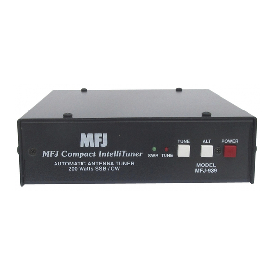
MFJ-939 Plug&Play IntelliTuner Automatic Antenna Tuner Instruction Manual Front Panel TUNE POWER MFJ Plug&Play IntelliTuner SWR TUNE AUTOMATIC ANTENNA TUNER MODEL 200 Watts SSB / CW MFJ-939 Figure 2 MFJ-939 Front Panel. SWR LED: A green LED that illuminates when the SWR is 1.5 or less. -
Page 9: Automatic/Semi-Automatic Tuning Mode
MFJ-939 Plug&Play IntelliTuner Automatic Antenna Tuner Instruction Manual ALT Button: Has two different functions based on the length of time you press and hold it before releasing. Press [ALT] quickly (less than one second) to select the primary memory bank to use. -
Page 10: Back Panel
An optional 12 volts DC 1.5 amp power supply, the MFJ-1316, is available from MFJ Enterprises, Inc. WARNING: Do not apply voltages greater than 18 volts to this unit, or permanent damage may result. -
Page 11: Installation
MFJ-939 Plug&Play IntelliTuner Automatic Antenna Tuner Instruction Manual Installation WARNING Never operate the tuner with its cover removed. Contact with the components inside ● the tuner while transmitting will result in painful RF burns. ● Locate the tuner so that the rear terminals are not accessible during operation. A single wire connection may have high voltage while transmitting. -
Page 12: General Tuner Setup And Cabling
Modification to Change Radio Model Changing the MFJ-939 to use with another model of radio is not difficult to do. For the radio model you are changing to obtain the proper interface cable and change the jumpers in the tuner to the positions needed for the new radio. -
Page 13: Operation
IC-706, IC-707, IC-718, IC-725, IC-728, IC-736, IC-738, IC-746, IC-756, IC-7000 Operation The operation of the MFJ-939I tuner is similar to the operation of the AH-3 or AH-4 described in the Icom radio’s operating manual. 1. Push and hold the [TUNER] button on the radio for one or two seconds to initiate automatic tuning process. - Page 14 Instruction Manual 1. Turn the tuner off. Set jumper JP2 to the “I” position. 2. For IC-7000, make sure jumper JP4 inside the MFJ-939 is removed. 3. Insert the 8-pin modular plug into the tuner’s RADIO INTERFACE jack. 4. Important: Make sure the DC power to the radio has been turned off. The radio does not fuse the DC power to the tuner, and damage to the radio can occur if the interface’s power connection...
-
Page 15: Mfj-939K Kenwood
TS-50S, TS-450S, TS-480HX, TS-570S, TS-590, TS-690S, TS-850S, TS-870S, TS-2000 Operation The operation of the MFJ-939K radio interface is similar to the operation of the AT-300 described in the Kenwood radio’s operating manual. 1. Press and hold the [AT TUNE] button on the radio for one second to initiate automatic tuning process. -
Page 16: Figure 8 Kenwood Interface Cable
Figure 8 Kenwood Interface Cable 1. Turn the tuner off. Set jumper JP2 to the “K” position. 2. Make sure jumper JP4 inside the MFJ-939 is installed. 3. Insert the 8-pin modular plug into the tuner’s RADIO INTERFACE jack. 4. Important: Make sure the DC power to the radio has been turned off. The radio does not fuse the DC power to the tuner, and damage to the radio can occur if the interface’s power connection... -
Page 17: Mfj-939Y Yaesu
Yaesu FT-100, FT-450, FT-847, FT-857, FT-897, FT-950 Operation for FT-100 The operation of the MFJ-939Y radio interface is similar to the operation of the FC-20 described in the Yaesu radio operating manual. 1. Press the [FUNC] key, as needed, to recall Operating Function Row 7 [MTR, TUN, PRO, VOX]. -
Page 18: Operation For Ft-950
Instruction Manual Operation for FT-950 The operation of the MFJ-5114Y radio interface is similar to the operation of the FC-40 described in the Yaesu radio operating manual. 1. Press the (TUNE) button on the radio briefly to enable the external tuner function. The “TUNER”... -
Page 19: Connections For The Ft-100
1. Turn the tuner off. Set jumper JP2 to the “Y” position. 2. Make sure jumper JP4 inside the MFJ-939 is installed. 3. Before connecting the MFJ-5114Y to your radio, follow the instructions in the radio’s manual for installing the FC-20 automatic antenna tuner. -
Page 20: Connections For Ft-950
Press and hold the [FUNC] or [F] key for one second to save the new setting and exit to normal operation. e. Turn the radio off, then on again. Do not connect the MFJ-5114Y before changing the Menu Mode #020 [CAT/LIN/TUN]. - Page 21 3. When tuning is completed, the radio will stop transmitting and you will be ready for operation on this frequency. Note the [TUNE] button on the tuner will not operate the MFJ-5114Y Yaesu radio interface. © 2006-2015 MFJ Enterprises, Inc.
-
Page 22: Mfj-939Y3 Ft-1000Mp Ft-2000 Ft-9000
The transceiver is controlled by the MFJ-939. To operate: 1. Press the [TUNE] button on the MFJ-939 for ½-2 seconds to initiate the tuning process. The radio will automatically transmit a low-power carrier and start the tuning process. When tuning is completed, the radio will stop transmitting and you will be ready for operation on this frequency. -
Page 23: Connections For Ft-1000Mp Series Of Radios
5. Connect a 12V 750 mA DC source to the MFJ-939. 6. Push the [POWER] button on the MFJ-939 to the in position. The radio may be powered on either before or after the tuner is powered on. -
Page 24: Connections For Ftdx-9000 Series Of Radios
Instruction Manual 5. Connect a 12V 750 mA DC source to the MFJ-939. 6. Push the [POWER] button on the MFJ-939 to the in position. The radio may be powered on either before or after the tuner is powered on. -
Page 25: Mfj-939Y4 Ft-2000
With this cable the operator can control the tuner and radio with a single push of the [TUNE] button on the front panel of the MFJ-939. Connections for FT-2000 series of radios... -
Page 26: Modification For Use With Alinco
If you press the [MENU] key momentarily, the new setting will not be saved. 3. Insert the 8-pin modular plug into the MFJ-939 RADIO INTERFACE jack. 4. Connect the RCA plug on the MFJ-5114Y4 to the TX REQ jack on the rear panel of the transceiver. -
Page 27: Miscellaneous
L- network is properly tuned. These limits are built into the MFJ-939 to prevent matching of extreme load impedance outside the tuner’s specification, which may result in excess voltage and/or current across the tuner’s components. -
Page 28: Morse Code And Beeps
Check your transceiver owner's manual to see if it has a foldback circuit. When an amplifier is used, the amplifier must be bypassed during tuning. Note: MFJ recommends that a transceiver-specific interface cable be used between the MFJ-939 and your transceiver to ensure that tuning only occurs at low power. -
Page 29: Grounding Hints
For operator safety, a good outside earth ground or water pipe ground should always be installed and connected to the case of the MFJ-939. Make certain the safety ground also connects to the transmitter and other station accessories. A wing-nut post marked GROUND is provided for ground connections. - Page 30 MFJ-939 Plug&Play IntelliTuner Automatic Antenna Tuner Instruction Manual A problem also occurs on 40 meters with this same antenna example. The feedline is now a multiple of a half-wave (60 to 70 feet) and connects to a full-wave high impedance antenna (100 to 140 feet). The half- wave line repeats the high antenna impedance at the tuner.
-
Page 31: Appendices
Within four seconds of releasing [ALT], press the [TUNE] button once. After releasing [TUNE] for four seconds, beep three times and resume normal operation. WARNING: If the MFJ-939 is not behaving properly or is acting erratically, try resetting the tuner to factory defaults. © 2006-2015 MFJ Enterprises, Inc. -
Page 32: Delete Entire Antenna Memory
Self Test A self-test routine will check the functions of the MFJ-939. This routine checks the LEDs, the front-panel buttons, the internal memory, the audio circuitry, and the power-down circuitry. During the self-test, you may stop the test by turning off the unit; however, this should NOT be done during the memory test or the memory could be corrupted. -
Page 33: Power-Down Circuit Test
MFJ-939 Plug&Play IntelliTuner Automatic Antenna Tuner Instruction Manual number of times the green LED blinks for X and the number of times the red LED blinks for Y. For example, green LED blinks one time and red LED blinks two times represent firmware version number 1.2. -
Page 34: Relay Test
239 coax cables, a Phillips screwdriver, and a tuning tool or small flat blade screwdriver. WARNING: Do not touch anything inside the tuner during operation! Serious, painful RF burns can result. WARNING: Never operate the MFJ-939 with its cover removed; dangerous voltages and currents can be present during operation. Never exceed tuner specifications. -
Page 35: Swr Bridge Calibration
50-ohm dummy load, three 50-ohm SO-239 coax cables, a Phillips screwdriver, a tuning tool or small flat blade screwdriver, and a cross-needle wattmeter (available only at MFJ factory). Therefore, this calibration can only be done at MFJ factory. -
Page 36: Jumper Settings
Disconnects power from the interface cable Connects power from the interface cable Table 10 Jumper JP1 Setting Jumper JP2 is used to set the MFJ-939 to the radio model in use. Note that no jumper disables the radio interface. Jumper... -
Page 37: In Case Of Difficulty
If you have any problem with this unit first check the appropriate section of this manual. If the manual does not reference your problem or your problem is not solved by reading the manual, you may call MFJ Technical Service at 662-323-0549 or the MFJ Factory at 662-323-5869. You will be best helped if you have your unit, manual and all information on your station handy so you can answer any questions the technicians may ask. -
Page 38: Figure 14 Block Diagram
Antenna Transmitter Inductors Impedance Bias 0-24 uH Sensor Sensor Frequency Voltage Counter Regulator Ground Relay Capacitors Drivers 0-3900 pF Radio Microcontroller Interface Memory Push LEDs Buzzer Buttons User Interface... -
Page 39: Full 12-Month Warranty
MFJ Enterprises, Inc. warrants to the original owner of the MFJ-939 by MFJ Enterprises, Inc. and purchased from an authorized dealer or directly from MFJ Enterprises, Inc. to be free from defects in material and workmanship for a period of 24 months from date of purchase provided the following terms of this warranty are satisfied. - Page 40 MFJ ENTERPRISES, INC. MFJ-939 Manual 300 Industrial Park Road Version 0A Starkville, MS 39759 Printed In U.S.A...
Need help?
Do you have a question about the Plug&Play Intellituner MFJ-939 and is the answer not in the manual?
Questions and answers
Have 939 y3, I downloaded the 939 manual will I be missing something?