Icom IC-A220 Instruction Manual
Vhf air band
Hide thumbs
Also See for IC-A220:
- Instruction manual (36 pages) ,
- Installation manual (2 pages) ,
- Service manual (233 pages)

Related Manuals for Icom IC-A220


Summary of Contents for Icom IC-A220
- Page 1 INSTRUCTION MANUAL VHF AIR BAND TRANSCEIVERS iA220 iA220E This device complies with Part 15 of the FCC Rules. Operation is subject to the condition that this device does not cause harmful interference.
-
Page 2: Explicit Definitions
L'utilisation de cet appareil dans une zone résidentielle peut provo- quer un brouillage préjudiciable, auquel cas l'utilisateur sera tenu de Icom, Icom Inc. and Icom logo are registered trademarks of Icom Incorporated corriger la situation à ses frais. (Japan) in Japan, the United States, the United Kingdom, Germany, France,... -
Page 3: Precautions
PRECAUTIONS R WARNING! NEVER DO NOT push the PTT when not actually intending to operate the transceiver with an earphone or other audio accessories at high volume lev- transmit. els. Continuous high volume operation may cause a ringing DO NOT in your ears. -
Page 4: Précautions
PRÉCAUTIONS R NE JAMAIS NE PAS utiliser l’émetteur-récepteur avec un d’utiliser ou d’exposer l’émetteur-récepteur en casque ou d’autres accessoires audio ayant un volume trop plein soleil ou à une tem pérature ambiante inférieure à –20°C élevé. Un volume continu trop fort peut entraîner un bour- ou supérieure à... -
Page 5: Safety Training Information
Electromagnetic Interference/Compatibility roof top at any place on the centre line along the vehicle During transmissions, your Icom radio generates RF energy in order to achieve 40 centimeters separation distance. that can possibly cause interference with other devices or In order to ensure this distance is met, the installation of systems. -
Page 6: Information En Matière De Sécurité
Dans le pire des cas, pour un petit véhicule, l'antenne doit être placée En mode de transmission, votre radio Icom produit de l'énergie de sur le toit, n'importe où dans l'axe central du véhicule, afin de RF qui peut provoquer des interférences avec d'autres appareils ou... -
Page 7: Table Of Contents
TABLE OF CONTENTS ■ Editing GPS memory ..........13 IMPORTANT ................i ■ Protecting memory .............13 EXPLICIT DEFINITIONS ............i FCC INFORMATION ............. i 4 OTHER FUNCTIONS ..........14 PRECAUTIONS ..............ii ■ Dualwatch operation ..........14 PRÉCAUTIONS ..............iii ■ Priority watch .............14 SAFETY TRAINING INFORMATION ........ -
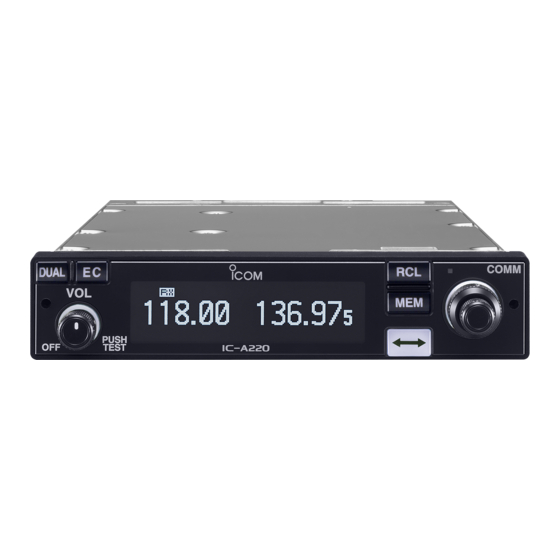
Page 8: Panel Description
PANEL DESCRIPTION ■ Front panel COMM DUAL MEMORY 118.00 121.52 CH09 SAMPLE PUSH TEST q DUAL SWITCH [DUAL] e VOLUME/POWER SWITCH [VOL] ➥ Push to turn Dualwatch operation ON or OFF. (p. 14) ➥ Turn [VOL] to switch the power ON or OFF. ➥... -
Page 9: Rear Panel
PANEL DESCRIPTION Rear panel r FREQUENCY EXCHANGE (FLIP-FLOP) SWITCH [ ■ ➥ Push to exchange the standby frequency with the ac- tive frequency. (p. 5) ➥ Hold down for two seconds to enter the direct frequen- cy setting mode. (p. 6) t MEMORY SWITCH [MEM] Hold down for two seconds to enter a displayed frequency into any blank regular memory channel or delete or revive... -
Page 10: Function Display
PANEL DESCRIPTION ■ Function display y MEMORY TYPE READOUT ➥ Displays “MEMORY” when the regular memory channel is selected. (p. 8) ➥ Displays “GRP01”–“GRP05” when the group memory channel is selected. (p. 8) DUAL MEMORY The group name is also displayed if the name has been 118.00 121.52 entered. -
Page 11: Basic Operation
BASIC OPERATION General description ■ Set the frequency normally The flow chart below shows the basic operating procedures. Set the desired frequency which will be used for the next op- You need to set the frequency, activate the frequency, and erating frequency in the standby frequency display. -
Page 12: Receiving And Transmitting
BASIC OPERATION ■ Receiving and transmitting Receiving When receiving a signal, “RX” is displayed and audio is Setting the standby frequency heard. • Rotate [VOL] to adjust the audio level. Rotate [DIAL] and [O-DIAL] to select the desired frequency • Adjust the squelch if necessary. Refer to ‘Squelch settings’ for de- as the standby frequency. -
Page 13: Directly Setting The Frequency
BASIC OPERATION ■ Directly setting the frequency Squelch settings ■ Adjusting the squelch You can also directly set the desired frequency. Adjust the squelch to mute undesired noise when no signal Hold down ] for two seconds to enter the direct frequen- received. -
Page 14: Memory Operation
MEMORY OPERATION General description Memory channel types ■ Regular memory channels (MEMORY) The transceiver has memory to store frequently used fre- Up to 20 memory channels can be selected. quencies. You can easily set the desired frequency by select- ing the channel from the memory. Group memory channels (GRP01–GRP05) The figure below shows the structure of the memory mode. -
Page 15: Basic Operation
MEMORY OPERATION Basic operation ■ Editing Regular memory/ ■ Group memory channels [RCL] to enter the mem- Push MEMORY 118.00 127.00 ory mode. Memory mode menu • The memory channel number is CH01 There are memory mode menus to edit the memory contents. displayed. -
Page 16: Clearing The Memory Contents
MEMORY OPERATION D Enter frequencies into memory channels D Clearing the memory contents To enter frequencies into memory channels, follow the steps You can clear unwanted memory channels. below. Push [RCL] to enter the memory mode. [DIAL] and [O-DIAL] to set the desired frequency Rotate •... -
Page 17: Entering Group Names
MEMORY OPERATION D Entering group names D Entering channel names (For only group memory channels) (For only regular memory channels) The memory groups can display a six character name in ad- The regular memory channels can display a six character dition to the group number (“GRP01”–“GRP05”). - Page 18 MEMORY OPERATION D Selecting channel tag names Channel tag list (For only group memory channels) DISPLAY MEANS The tag name can be set to a three character name, in ad- NAME Group* GPS* dition to the group number. It is convenient for separating _ _ _ –...
-
Page 19: Selecting A Weather Memory Channel
MEMORY OPERATION Selecting a weather memory ■ History memory channel ■ channel The transceiver has 20 history memory channels. (For only U.S.A. version transceivers) When pushing [ ], the standby frequency is stored into a history memory channel. The U.S.A. version transceivers have built-in VHF marine WX The frequencies are stored into the history memory channel (weather) channels. -
Page 20: Selecting A Gps Memory Channel
MEMORY OPERATION ■ Selecting a GPS memory Editing GPS memory ■ channel The received GPS memory data is stored in the desired group memory channel. When connected to an external GPS receiver* with an airport NOTE: frequency database, you can transfer frequency data such as The GPS memory data is overwritten if the se- nearby airports to the GPS memory (maximum 10 memory lected GPS memory channel already contains other data. -
Page 21: Other Functions
OTHER FUNCTIONS ■ Dualwatch operation ■ Priority watch The Dualwatch operation monitors the active frequency at The Priority watch operation monitors the active frequency certain intervals, even when receiving a signal on the standby at certain intervals* even when receiving a signal on the frequency. -
Page 22: Using The Lock Function
OTHER FUNCTIONS Using the lock function Accessing the 121.5 MHz ■ ■ emergency frequency The lock function prevents accidental frequency changes and accidental function activation. There are two lock modes, The transceiver can be set to the 121.5 MHz emergency fre- panel lock and dial lock. -
Page 23: Enabling The Intercom
OTHER FUNCTIONS Enabling the intercom Setting the frequency step ■ ■ When two headsets are connected to the transceiver, you You can select Frequency steps of 8.33 kHz or 25 kHz in the can use them as a voice-activated intercom. menu mode. -
Page 24: Scanning The Weather Memory Channels
OTHER FUNCTIONS Scanning the weather memory channels ■ (For only U.S.A. version transceivers) Scanning automatically searches for weather channel sig- When no signal is received on the weather channel: nals. • “NO WTH” is displayed even searches “WX01” to “WX10” chan- Repeatedly scans all weather memory channels. -
Page 25: Menu Mode
MENU MODE Using the menu mode ■ • Settings menu items The menu mode is accessible at power ON and allows you Item Ref. Item Ref. to set seldom-changed settings. You can customize the trans- ceiver settings to suit your preferences and operating style. SQL LEVEL p. - Page 26 MENU MODE • Configuration menu items Using the Configuration menu Item Ref. Item Ref. While holding down [DUAL], rotate [VOL] to turn ON the transceiver’s power. AUTO SQL p. 22 DISP HIGH p. 24 • Configuration menu is displayed. SQL SW p.
-
Page 27: Settings Menu Items
MENU MODE ■ Settings menu items D Intercom 1 microphone audio input level “IN- D AM squelch level “SQL LEVEL” COM LV1” Adjust the squelch level for AM mode operation. Sets the intercom 1 microphone input level. In order to receive signals properly, the squelch must be ad- •... - Page 28 MENU MODE D Setting microphone 1 Gain “MIC1 GAIN” D External input level “AUX LEVEL” Sets microphone 1’s gain. Sets the external input level. * Displayed only when the External input “AUX IN” item in the Configu- • –010 to 010: Sets the microphone 1’s gain to between –10 and ration menu (p.
-
Page 29: Configuration Menu Items
MENU MODE items Configuration menu D Dualwatch interval “DW INTERVAL” ■ Sets the interval time while operating Dualwatch or weather D Auto squelch “AUTO SQL” scan. • FAST: Sets the interval to 300 milliseconds. Sets the Auto squelch function. • MID: Sets the interval to 600 milliseconds. -
Page 30: Group Memory Channel Display
MENU MODE D Group memory channel display D Dimmer auto mode “DISP AUTO” “GRP MEMORY” Sets the method to automatically control the dimmer bright- ness.* Select whether the label is displayed or not. * Displayed only when the Dimmer mode “DISP MODE” item in the •... - Page 31 MENU MODE D Dimmer brightness (High) “DISP HIGH” D External input “AUX IN” Sets the maximum brightness level in the automatic adjust- Set the audio usage input from an external audio device. ment range.* Refer to ‘INSTALLATION GUIDE’ for an external audio device * Displayed only when the Dimmer mode “DISP MODE”...
- Page 32 MENU MODE D Time-Out-Timer “TIME OUT” D Remote exchange “REM SWAP” To prevent accidental prolonged transmission, the transceiver Sets the remote control (p. 16) to use the frequency exchange has a time-out-timer.The function inhibits continuous trans- switch or not. missions longer than the set time period. •...
-
Page 33: Options
Approved Icom optional equipment is designed for optimal performance when used with an Icom transceiver. Icom is not responsible for the destruction or damage to an Icom transceiver in the event the Icom transceiver is used with equipment that is not manufactured or approved by... -
Page 34: Specifications
• Intermediate frequencies: 1st 38.85 MHz 10 GPS memory channels 450 kHz • Mode: • Sensitivity: 6K00A3E/5K60A3E IC-A220 AM Less than 2 μV (pd) 16K0G3E at 6 dB S/N • Power supply requirement: 13.80 V/27.50 V DC Less than 1.4 μV (negative ground) at 12 dB SINAD •... - Page 35 • Channel spacing: 25 kHz (Actual frequency is displayed.) Operating Frequency Channel spacing Channel ID • Selectivity (with 8.33 kHz channel spacing): (MHz) (kHz) (Displayed Frequency) 118.0000 118.000 IC-A220 6 dB ±2.778 kHz 118.0250 118.025 60 dB ±7.37 kHz 118.0500 118.050 IC-A220E 6 dB ±2.8 kHz 118.0750 118.075...
-
Page 36: Information
INFORMATION Country code list Disposal ■ ■ The crossed-out wheeled-bin symbol on your • ISO 3166-1 product, literature, or packaging reminds you Country Codes Country Codes that in the European Union, all electrical and 1 Austria 18 Liechtenstein electronic products, batteries, and accumulators (rechargeable batteries) must be taken to des- 2 Belgium 19 Lithuania... -
Page 37: Index
INDEX AM squelch level ..............20 Emergency frequency ............15 Automatic noise limiter ............20 Enter frequencies into memory channels ......9 Auto squelch ...............22 Entering channel names .............10 Entering group names ............10 External dimmer control .............23 Basic operation ..............4 External input ..............24 Beep tone level ..............21 External input gain ..............24 External input level .............21 Channel tag ................11... - Page 38 INDEX Intercom ................16 Rear panel ................2 Intercom 1 microphone audio input level ......20 Receiving ................5 Intercom 1 squelch level .............22 Regular memory ..............8 Intercom 2 microphone audio Input level ......20 Remote control ..............16 Intercom 2 squelch level .............22 Remote exchange ..............25 Intercom usable setting ............24 Remote incom ..............25 Interlock ................25...
- Page 39 MEMO...
- Page 40 A-7210D-1EX-q Printed in Japan 2015 Icom Inc. © 1-1-32 Kamiminami, Hirano-ku, Osaka 547-0003, Japan Printed on recycled paper with soy ink.
Need help?
Do you have a question about the IC-A220 and is the answer not in the manual?
Questions and answers