Advertisement
Table of Contents
- 1 Table of Contents
- 2 Cautions and Informations
- 3 Specifications
- 4 Designation of Various Parts
- 5 Dimensions
- 6 List of Electrical Parts
- 7 Wiring Diagram
- 8 Functions
- 9 Ambient Temperature
- 10 Assembling Procedures of Main Parts and Cautions
- 11 Cooling Unit
- 12 Replacement Parts List
- Download this manual
SJ-21P
Refrigerant; HFC-134a
Refer to "HFC-134a COOLING UNIT" Service Manual for handling this refrigerant.
CAUTIONS AND INFORMATIONS ................................................................................................................... 2
SPECIFICATIONS ............................................................................................................................................. 3
DESIGNATION OF VARIOUS PARTS .............................................................................................................. 4
DIMENSIONS .................................................................................................................................................... 6
LIST OF ELECTRICAL PARTS ......................................................................................................................... 8
WIRING DIAGRAM ............................................................................................................................................ 8
FUNCTIONS .................................................................................................................................................... 10
ASSEMBLING PROCEDURES OF MAIN PARTS AND CAUTIONS .............................................................. 14
COOLING UNIT ............................................................................................................................................... 22
REPLACEMENT PARTS LIST ........................................................................................................................ 24
SERVICE MANUAL
REFRIGERATOR-FREEZER
MODELS
In the interests of user-safety (Required by safety regulations in some
countries) the set should be restored to its original condition and only
parts identical to those specified should be used.
SJ-D25P
TABLE OF CONTENTS
SHARP CORPORATION
SJ-21P-GY
SJ-D25P-GY
DESTINATION .................. F
1
SJ-21P
SJ-D25P
S9120SE25CPSF
page
Advertisement
Table of Contents

Related Manuals for Sharp SJ-21P-GY


Summary of Contents for Sharp SJ-21P-GY
-
Page 1: Table Of Contents
SJ-D25P SERVICE MANUAL S9120SE25CPSF REFRIGERATOR-FREEZER MODELS SJ-21P-GY SJ-D25P-GY In the interests of user-safety (Required by safety regulations in some countries) the set should be restored to its original condition and only parts identical to those specified should be used. SJ-21P SJ-D25P Refrigerant;... -
Page 2: Cautions And Informations
SJ-21P SJ-D25P CAUTIONS AND INFORMATIONS In case of following troubles, the cause is not related with the failure of refrigerator. Please mention the correct way to the customer for the use of refrigerator when the repairing. 1. Some foods freezed in the refrigerator compartment. Do not place food directly in front of cold air outlet. -
Page 3: Specifications
Bottle pocket R door pocket Freezer F-partition tray Compartment F tray F door pocket Ice cube maker Twin ice cube maker COLOR Items SJ-21P-GY,SJ-D25P-GY Outside color Gray Inside color White RATING Models SJ-21P SJ-D25P Rated voltage (V~) 110 Rated frequency... -
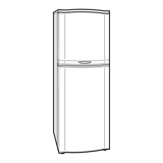
Page 4: Designation Of Various Parts
SJ-21P SJ-D25P DESIGNATION OF VARIOUS PARTS EXTERNAL DESCRIPTION By Operation manual SJ-21P SJ-D25P Fig. D-1 The names in parenthesis" [ ]" are the denominations used in the REPLACEMENT PARTS LIST. 15. Table top [Top table] 1. Freezer shelf (Small) [F-partition tray] Do not place hot objects on the table top. - Page 5 SJ-21P SJ-D25P CONSTRUCTIONS Mark: Cold air flow Fan motor Defrost thermostat F-temp. control knob Evaporator Defrost heater R thermostat Defrost timer Lamp V tray Vegetable case Compressor Fig. D-2 (SJ-21P) Mark: Cold air flow Fan motor Defrost thermostat F-temp. control knob Evaporator Defrost heater R thermostat...
-
Page 6: Dimensions
SJ-21P SJ-D25P DIMENSIONS OUTER DIMENSIONS AND CLEARANCE more than more than more than more than ( Unit : mm ) Fig. E-1(SJ-21P) more than more than more than more than ( Unit : mm ) Fig. E-2(SJ-D25P) - Page 7 SJ-21P SJ-D25P INNER DIMENSIONS (Unit : mm) Fig. E-3(SJ-21P) (Unit : mm) Fig. E-4(SJ-D25P)
-
Page 8: List Of Electrical Parts
SJ-21P SJ-D25P LIST OF ELECTRICAL PARTS ITEMS TYPE NAME RATING SPECIFICATIONS Defrost thermostat S101 125V,15A Open : 10˚C , Close : 1˚C Timer TMDFX04FB2 100-127V Integration type 50/ 60Hz Cycle time : 10h (60Hz) Delay time : 4m (60Hz) Thermo. fuse (defrost) SF70E 250V,10A Cut off temperature : 70˚C Door switch... - Page 9 SJ-21P SJ-D25P : GRAY FAN MOTOR (G-1) : BROWN (B-1) : ORANGE (B-3) DEFROST : RED (Y-1) THERMOSTAT : PINK : BLUE : BLACK (Y-2) DEFROST (W-1) : SKY-BLUE HEATER (W-1) : WHITE THERMO. : YELLOW (BK-1) FUSE (B-2) DOOR SWITCH (SB-1) DEFROST (R-1)
-
Page 10: Functions
SJ-21P SJ-D25P FUNCTIONS 1. ADJUSTABLE TEMPERATURE CONTROL (1) Temperature control FREEZER COMPARTMENT regulates the quantity of cold air to the freezer. " "(7) setting directs more cold air to the freezer compartment. (making the freezer compartment colder) " "(1) setting directs less cold air to the freezer compartment. (making the freezer compartment less colder) KNOB PURPOSE... -
Page 11: Ambient Temperature
SJ-21P SJ-D25P (3) Temp. control system Freezer Temp. Control Knob The Freezer temp. control knob regulates the quantity of cold air to the freezer. " " (7) setting directs more cold air to the freezer compartment. (making the freezer compartment colder) "... - Page 12 SJ-21P SJ-D25P 2. DEFROSTING (2) Where is melted frost brought. (1) No defrosting operation is necessary. 1. Melted frost is brought into Evaporating pan No defrosting operation is necessary. at the back of the set and is evaporated here As this machine is so designed that a built-in by the heat of compressor.
- Page 13 SJ-21P SJ-D25P (4) As a reference to determine the causes of trouble, malfunction and phenomena are described below. Refer to the following when repairing. 1. Disconnection of Defrost heater As off-cycle defrosting is performed, the defrosting time is extremely prolonged. Each time defrosting is started, the freezer temperature rises and a portion of ice and stored foods are melted.
-
Page 14: Assembling Procedures Of Main Parts And Cautions
SJ-21P SJ-D25P ASSEMBLING PROCEDURES OF MAIN PARTS AND CAUTIONS CAUTION: DISCONNECT THE UNIT FROM THE POWER SUPPLY BEFORE ANY REPAIRING. 1. F-LOUVER ASSEMBLY Aluminum tape (65mm x 290mm, 65mm x 125mm) A-sealer EVC B F-louver sealer F-louver E.V. duct AL E.V. - Page 15 SJ-21P SJ-D25P 5. Set E.V. duct ass'y to F-louver. 6. Stick F-louver sealer to F-louver. F-louver E.V duct ass’y Fig. A-6 1~ 3mm Sec. AA Sec. BB Fig. A-7...
- Page 16 SJ-21P SJ-D25P 2. FM COVER ASSEMBLY AND THERMAL FUSE D ASSEMBLY FM cover ass'y Tape Clip Tape Thermal fuse D ass'y Fig. A-8 FM COVER ASSEMBLY Motor cushion Fan motor A-sealer FM Motor holder Motor cover Propeller fan 90 Fastening band A Fan clamp Defrost thermo.
- Page 17 SJ-21P SJ-D25P 1. Stick A-sealer FM to Motor holder. Fan motor Motor cushion Motor holder Motor holder A-sealer A-sealer FM Sec. AA A-sealer FM Motor cover Motor cushion finish start Sec. Horizontal Center Fig. A-10 A-sealer FM Motor holder Motor cover 2.
- Page 18 SJ-21P SJ-D25P 7. Set Propeller fan 90 and Fan clamp to " 6 " ass'y as shown in Fig. A-15. slit Fan clamp Fan clamp shaft slit Propeller fan 90 7.5 0.5 Propeller fan 90 " 6 " ass’y Fan clamp fan boss GOOD NO GOOD...
- Page 19 SJ-21P SJ-D25P 3. R-CBOX ASSEMBLY Lamp socket R-air guider ass’y Lamp Defrost timer R-thermostat Insulating tube Warning label F-temp. control knob R-Cbox cover D timer lead ass’y Fig. A-17 5. Fix R thermostat with screw and make up the 1. Connect D timer lead ass'y to Defrost timer, tube of R thermostat as shown Fig.
- Page 20 SJ-21P SJ-D25P (2) Replacement of Def. heater ass'y. 4. DEFROST HEATER 1. Disconnect the lead wires inserted in the rib of center (1) Taking-out Evaporator partition (Fig. A-25 : 8 pcs.). 1. Take out F-louver ass'y (Fig. A-22). Evaporator Food liner convex part Tape Fig.
- Page 21 SJ-21P SJ-D25P 4. Replace Defrost heater with new one. 7. Stick the longer wire to the Drain support by aluminum tape (2 pieces), and wind vinyl tape (2 pieces) to lead wires of Def. heater ass'y by aluminum tape as shown in Fig.
-
Page 22: Cooling Unit
SJ-21P SJ-D25P (3) Installing of Evaporator 1. Install Evaporator as shown in Fig. A-22 in the reverse order of Fig. A-23. 2. Correct the deformed fin. NOTE 1. When installing Evaporator, take care not to deform significantly and break the pipes. 2. - Page 23 SJ-21P SJ-D25P Location Dryer Capillary tube Hot pipe Charge pipe Evaporator Charge pipe E Back condenser Suction pipe Discharge connector P connector Compressor Fig. C-2 Back condenser S.P connector to Hot pipe to Suction pipe Pinch Point Hot pipe to Dryer Charge pipe to Dryer Discharge P.
-
Page 24: Replacement Parts List
SJ-21P SJ-D25P REPLACEMENT PARTS LIST ( SJ-21P/D25P) REF. NO. PART NO. DESCRIPTION Q'TY CODE SJ-21P SJ-D25P ELECTRIC PARTS FFS-TA044CBK0 Fuse ass'y QACC-A133CBE0 Source cord QSWTDA025CBE0 Defrost timer RMOTRA044CBE0 Fan motor RTHM-A085CBE0 R thermostat FTHM-A034CBKZ Defrost thermo.ass'y 1-11 RLMP-A002CBE0 Lamp 1-12 QSW-PA076CBEA Door switch 1-13... - Page 25 SJ-21P SJ-D25P REF. NO. PART NO. DESCRIPTION Q'TY CODE SJ-21P SJ-D25P OTHER PARTS LX-BZ0202JBE0 Special screw QTAN-A012CBE0 Solderless term. b QTAN-A013CBE0 Solderless term. a ATTACHMENT PARTS FSRA-A199CBYZ Ice cube maker USRA-A214CBFB R tray l USRA-A215CBFB R tray s USRA-A212CBFB F tray UTNA-A260CBFB Free set shelf b UTNA-A261CBFB...
- Page 26 SJ-21P SJ-D25P DOOR PARTS 3-1-1 5-15 5-16 3-25 3-1-1 3-13 3-1-2 3-12 5-19 5-17 3-1-2 SJ-21P SJ-D25P...
- Page 27 SJ-21P SJ-D25P CABINET PARTS 2-50 6-11 6-10 2-47 2-10 2-45 2-21 5-12 2-23 2-35 1-15 2-32 2-45 2-32 2-22 2-31 2-33 2-45 2-30 2-43 2-29 2-26 2-28 2-34 2-42 2-13 1-12 2-24 2-46 5-10 2-25 2-55 2-12 2-53 2-15 2-44 2-38 1-23 1-11...
- Page 28 No part of this publication may be repro- duced, stored in retrieval systems, or transmitted in any form or by any means, electronic, mechanical, photocopying, re- cording, or otherwise, without prior written permission of the publisher. 2001 SHARP CORP. (09K0.10E) Printed in Japan 21CPRF/ 25CPSF...