
Related Manuals for Planet ISW-504PT


Summary of Contents for Planet ISW-504PT
- Page 1 5-Port 10/100Mbps with 4-Port PoE Industrial Fast Ethernet Switch ISW-504PT / ISW-514PT / ISW-514PT15 / ISW-514PTF User's Manual...
- Page 2 Trademarks Copyright © PLANET Technology Corp. 2010 Contents subject revision without prior notice PLANET is a registered trademark of PLANET Technology Corp. All other trademarks belong to their respective owners. Disclaimer PLANET Technology does not warrant that the hardware will work...
-
Page 3: Fcc Warning
WEEE separately. Revision PLANET 5-Port 10/100Mbps with 4-Port PoE Industrial Fast Ethernet Switch – Wide Temperature User’s Manual For ModelS: ISW-504PT / ISW-514PT / ISW-514PT15 / ISW-514PTF Revision: 1.0 (July, 2010) Part No: EM-ISW-5XXPT Series_v1.0 (2350-AH0230-000) -
Page 4: Table Of Contents
Table of Contents 1. Introduction ................5 1.1 Package Contents ............... 5 1.2 How to Use This Manual ............5 1.3 Product Features ..............6 2. Installation ................11 2.1 Product Description ............11 2.1.1 Switch Front Panel ............12 2.1.2 LED Indicators ............12 2.1.3 Switch Upper Panel ...........13 2.1.4 Wiring the Power Inputs ..........14 2.1.5 Wiring the Fault Alarm Contact ........15... -
Page 5: Introduction
1. Introduction 1.1 Package Contents Check the contents of your package for following parts: ● Industrial Fast Ethernet Switch x 1 ● User's Manual x 1 ● DIN Rail Kit x 1 ● Wall Mount Kit x 1 If any of these are missing or damaged, please contact your dealer immediately, if possible, retain the carton including the original packing material, and use them against to repack the product in case there is a need to return it to us for repair. -
Page 6: Product Features
1.3 Product Features Physical Port Ports Fiber Optical Interface Model Name Copper Optical Mode Connector Distance 5 x 10 / ISW-504PT 100Base-TX ISW-514PT Multi-Mode ISW-514PT15 Single-Mode 15km 4 x 10 / 100Base-TX 100Base-FX Optional SFP Depend on ISW-514PTF Module SFP Module IEEE 802.3af PoE... -
Page 7: Product Specifications
® Supports EFT protection 6000V DC for power line ® Supports 6000V DC Ethernet ESD protection ® -40 to 75°C operating temperature 1.4 Product Specifications Model ISW-504PT ISW-514PT Hardware Specification 10/100Base-TX Ports 100Base-FX interface IEEE 802.3af PoE ports Dimensions (W x D x H) 135mm x 87.8mm x 56mm... - Page 8 Switch Specification Switch Processing Scheme Store-and-Forward Address Table 2K entries Back Pressure for Half Duplex Flow Control IEEE 802.3x Pause Frame for Full Duplex Switch fabric 1Gbps Throughput 0.74Mpps (Packet per second) 1. 10/100Base-TX: 1. 10/100Base-TX: Cat. 3, 4, 5, Cat.
- Page 9 Model ISW-514PT15 ISW-514PTF Hardware Specification 10/100Base-TX Ports 100Base-FX interface IEEE 802.3af PoE ports Dimensions (W x D x H) 135mm x 87.8mm x 56mm Weight 842g Power Requirement 24 or 48V DC Installation DIN Rail Kit and Wall Mount Ear Power over Ethernet PoE Standard IEEE 802.3af Power over Ethernet / PSE...
- Page 10 1. 10/100Base-TX: 1. 10/100Base-TX: Cat. 3, 4, 5, Cat. 3, 4, 5, 5e, 6 UTP cable 5e, 6 UTP cable (100meters max.) (100meters max.) 2. EIA/TIA-568 2. EIA/TIA-568 100-ohm STP 100-ohm STP (100meters max.) (100meters max.) 3. Single-mode optic 3. 50 / 125µm or fiber 9 / 125μm 62.5 / 125µm Network cables...
-
Page 11: Installation
4 PoE compliant devices at the distance up to 100 meters through the 4-pair Cat 5 / 5e UTP wire. With Data and Power over Ethernet from one unit, the ISW-504PT / ISW-514PT / ISW-514PT15 / ISW-514PTF shall reduce cables deployment and eliminates the need for dedicated electrical outlets on the wall, ceiling or any unreachable place. -
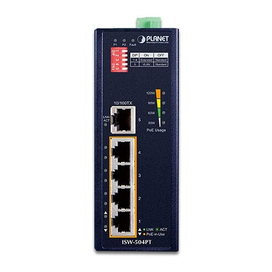
Page 12: Switch Front Panel
2.1.1 Switch Front Panel Figure 2-1 & 2-2 & 2-3 show a front panel of Industrial Fast Ethernet Switch. Figure 2-1 ISW-504PT Figure 2-2 ISW-514PT / Figure 2-3 ISW-514PTF front panel 514PT15 front panel front panel 2.1.2 LED Indicators... -
Page 13: Switch Upper Panel
¢ Per 10/100Base-TX Port Color Function Indicate the link through that port is Light successfully established at 10 or 100Mbps. Link / ACT Green Indicate that the Switch is actively Blink sending or receiving data over that port. ¢ Per 100Base-FX Port Color Function Indicate the link through that port is... -
Page 14: Wiring The Power Inputs
2.1.4 Wiring the Power Inputs The 6-contact terminal block connector on the top panel of Industrial Fast Ethernet Switch is used for two DC redundant powers input. Please follow the steps below to insert the power wire. 1. Insert positive / negative DC power wires into the contacts 1 and 2 for POWER 1, or 5 and 6 for POWER 2. -
Page 15: Wiring The Fault Alarm Contact
2.1.5 Wiring the Fault Alarm Contact The fault alarm contacts are in the middle of the terminal block connector as the picture shows below. Inserting the wires, the Industrial Fast Ethernet Switch will detect the fault status of the power failure, or port link failure (available for managed model) and then forms an open circuit. -
Page 16: Install Din-Rail Mounting
2.2.1 Install DIN-Rail Mounting The DIN-Rail is screwed on the Industrial Fast Ethernet Switch when out of factory. When need to replace the wall mount application with DIN-Rail application on Industrial Fast Ethernet Switch , please refer to following figures to screw the DIN-Rail on the Industrial Fast Ethernet Switch. - Page 17 Step 4: Please refer to following procedures to remove the Industrial Fast Ethernet Switch from the track. Step 5: Lightly press the button of DIN-Rail for remove it from the track. 2.2.2 Wall Mount Plate Mounting To install the Industrial Fast Ethernet Switch on the wall, please follows the instructions described below.
-
Page 18: Application
WLAN AP more easily and efficiently. PoE IP Cam 24/48V DC Intranet PWR1 (Redundant Power) 48V DC PWR 2 400 Watts UPS ISW-504PT PoE VoIP ATA PoE IP Phone PoE Wireless AP Power Line (DC) 100Base-TX UTP 100Base-TX UTP with PoE 2.4GHz 802.11n... -
Page 19: Installation Steps
3.1 Installation Steps Step 1: Unpack the Industrial Fast Ethernet Switch. Step 2: Check the DIN-Rail is screwed on the Industrial Fast Ethernet Switch. (Please refer to DIN-Rail Mounting section for DIN- Rail installation. If you want to wall mount the Industrial Fast Ethernet Switch, then please refer to Wall Mount Plate Mounting section for wall mount plate installation. -
Page 20: Switch Operation
4. Switch Operation 4.1 Address Table The Industrial Fast Ethernet Switch is implemented with an address table. This address table composed of many entries. Each entry is used to store the address information of some node in network, including MAC address, Port No. and etc. This information comes from the learning process of Industrial Fast Ethernet Switch. -
Page 21: Store-And-Forward
4.4 Store-and-Forward Store-and-Forward is one type of packet-forwarding techniques. A Store-and-Forward Industrial Switch stores incoming frames in an internal buffer and checks any error from the frames before transmission. No error packets occurrence, it is the best choice when a network needs efficiency and stability. -
Page 22: Troubleshooting
5. Troubleshooting This chapter contains information to help you solve issues. If the Industrial Fast Ethernet Switch is not functioning properly, make sure the Industrial Fast Ethernet Switch was set up according to instructions in this manual. The Link LED is not light Solution: Check the cable connection of the Industrial Fast Ethernet Switch. -
Page 23: Appendix A: Networking Connection
APPENDIX A: Networking Connection A.1 Switch’s RJ-45 Pin Assignments 10/100Mbps, 10/100Base-TX RJ-45 Connector pin assignment MDI Media Dependant MDI-X Media Dependant Contact Interface Interface-Cross Tx + (transmit) Rx + (receive) Tx - (transmit) Rx - (receive) Rx + (receive) Tx + (transmit) 4, 5 Not used Rx - (receive) - Page 24 There are 8 wires on a standard UTP/STP cable and each wire is color- coded. The following shows the pin allocation and color of straight cable and crossover cable connection: Straight Cable SIDE 1 SIDE 2 1 2 3 4 5 6 7 8 SIDE 1 1 = White/Orange 1 = White/Orange...
Need help?
Do you have a question about the ISW-504PT and is the answer not in the manual?
Questions and answers