Table of Contents
Advertisement
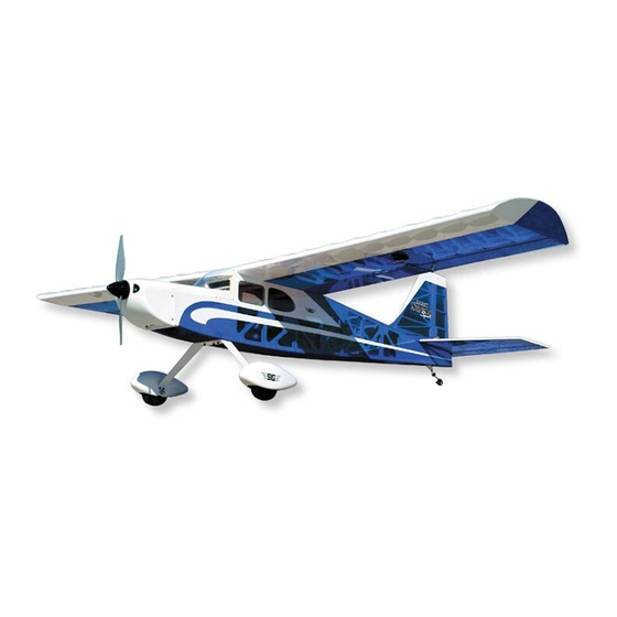
Shown with optional 2" Spinner
(not included)
Wing Span:
78 in.
Wing Area:
1148 sq. in.
Length:
65 in.
Flying Weight:
8 - 8.5 lbs.
Wing Loading: 12.0 - 13.0 oz./sq.ft.
Radio: 4-Channel with 5 Standard Servos
Glow Power:
.40-.53 cu.in. (6.5-8.7 cc) 2-Stroke Engine
.50-.61 cu.in. (8.1-10 cc) 4-Stroke Engine
Electric Power: Brushless Outrunner Motor
(600-1100w; 500-800kv; 42-50mm case dia.)
60-75A Speed Control (ESC)
4-6s 4000-5000 mah Lipo Battery Pack
SIG MFG. CO., INC. PO Box 520 Montezuma, IA 50171-0520
(1980 mm)
(74.1 dm²)
(1651 mm)
(2720 - 2950 g)
(36-39 g/dm2)
www.sigmfg.com
© Copyright 2013, SIG Mfg Co., Inc.
Advertisement
Table of Contents

Related Manuals for SIG Kadet Senior Sport


Summary of Contents for SIG Kadet Senior Sport
- Page 1 .50-.61 cu.in. (8.1-10 cc) 4-Stroke Engine Electric Power: Brushless Outrunner Motor (600-1100w; 500-800kv; 42-50mm case dia.) 60-75A Speed Control (ESC) 4-6s 4000-5000 mah Lipo Battery Pack SIG MFG. CO., INC. PO Box 520 Montezuma, IA 50171-0520 www.sigmfg.com © Copyright 2013, SIG Mfg Co., Inc.
-
Page 2: Assembly Manual
R/C model aircraft. Assembly of your KADET SENIOR SPORT is fast and simple when following the detailed instructions in this manual. We urge NOTE: If you intend to use your KADET SENIOR for “heavy lift- you to read this assembly manual completely before assembly. - Page 3 Make sure materials available: you understand the motor manufacturer’s numbering system A selection of glues - SIG Thin, Medium, & Thick CA Glue when shopping for a motor. CA Accelerator, CA Debonder...
-
Page 4: Covering Material
K (2) 3-1/2” dia. Main Wheels K (2) 4mm dia. x 62mm Axles K (2) 7.5mm Hex Nuts; for axles K (4) 4mm ID Wheels Collars; for axles K (1) Right Fiberglass Wheel Pant; painted white K (1) Left Fiberglass Wheel Pant; painted white Tailwheel COVERING MATERIAL K (1) Tailwheel Assembly, including Wheel, formed Wire, Nylon... -
Page 5: Installing The Aileron Servos
Once your iron is set to the correct temperature, go over the entire INSTALLING THE AILERON SERVOS framework of the airplane, making sure that the covering is se- For the following steps you will need: curely bonded to the structure everywhere the covering comes in (1) Right Wing Panel contact with the wood underneath. -
Page 6: Hinging The Ailerons
c) Adjust the aileron so that the tip of the aileron is flush with the wing tip. The ailerons should be tight against the pins in the hinges to minimize the gap between the wing and the aileron. The aileron is now in the proper position for permanently gluing them in place with thin CA glue. -
Page 7: Fuselage Assembly
Pin. Then test fit the wing assembly on the fuselage. The tab Metal R/C Clevis. Screw the Hex Nut on the Aileron Pushrod Wire that is formed by the two panels at the center, leading edge, fits all the way up to the end of the threads. Then screw the metal into the cutout in the front fuselage former. - Page 8 axle and test to make sure it spins freely. If it does not turn freely, TAIL SURFACE & TAILWHEEL INSTALLATION drill out the plastic hub of the wheel with an 11/64" or #17 drill bit. For the following steps you will need: (1) Fuselage (1) Wing K 9) Slide a second wheel collar onto the axle and up to the...
- Page 9 glue is applied in the next step. You can now remove the pins and c) Keep sliding the wire in until the short top leg exits the slot take the stabilizer off the fuselage for gluing. in the stabilizer. ❑ 14) The horizontal stabilizer can now be glued permanently onto the rear of the fuselage.
- Page 10 e) Finish the rudder installation by gluing the CA Hinges in (2) Metal RC Clevis place with Thin CA, using the same techniques you did for the (2) small pieces of Fuel Tubing aileron hinges back in Step 2. (2) Pushrod Snap Keepers f) After all the glue is dry, adjust the wheel collar to sit snug (1) Radio Receiver (not furnished) against the bottom of the nylon tailwheel bearing.
-
Page 11: Electric Power System
clevis can’t open up and come loose from the control horn by slid- ing the small piece of fuel tubing over the arms of the clevis. Also tighten the M2 Hex Nut up against the back of the clevis Elevator servo shown - proceedure is the same for the Rudder servo. ❑... - Page 12 ❑ 27) NOTE: The mounting of the electric motor in the KADET and drill out the SENIOR assumes that your motor has a typical "X" or "cross" mounting holes with mounting plate on the back of the motor. a 7/32" dia. drill. In- stall four M4 Blind Also note that the firewall portion of the laser-cut plywood motor Nuts in the holes, on...
- Page 13 b) Decide on a good location for the ESC in the nose of the Optional: In addition to the two straps, it is a good idea to use airplane. The most likely location is against the fuselage side, out hook-&-loop tape (not furnished) on the bottom of your battery of the way of the battery pack.
- Page 14 for either 2-stroke or 4-stroke power plants is basically the same. The main difference is often times the throttle arm location on the carburetor. The materials provided in this kit should be useful for almost any 2-stroke engine installation. Installation of a 4-stroke engine may require some alterations and/or specialized fittings (not supplied).
- Page 15 c) Once you are satisfied with the fit of both the fuel clunk line Then slide the fuel tank in place, through the back of the plywood and the vent line you can tighten the screw to expand the rubber fyel tank support and up against the back of the firewall, with the stopper and seal the stopper in the tank.
- Page 16 to come out the vent line! Re-connect the fuel lines and you are sliding it back until approximately 1/2" of the nylon tube remains ready to start the engine. in front of the firewall. f) Now slip the plain end of the pushrod wire inside the pushrod keeper.
-
Page 17: Install Side Windows
velope a pattern and mark it on the cowling for guidance when screw. Recheck the overall fit of the cowl and make any adjust- you are cutting. ments needed with tape to hold it in place. Then on the opposite a) Begin by marking a centerline on the top of the cowl. -
Page 18: Control Surface Travel
CONGRATULATIONS! CONTROL SURFACE TRAVEL Your KADET SENIOR is completely assembled. However, it is NOT ready for flight! There are a few very critical pre-flight tasks Double check the alignment and movement of all the controls one we must perform before flying. These are extremely important more time! Adjust all of your pushrod linkages so that the control and should be approached with patience and care. -
Page 19: Academy Of Model Aeronautics
trols for the first time. Let the instructor get the model airborne On the initial test flight, you may find that you need a little "down" and flying straight and level at a safe attitude (“several trim in the elevator to get your KADET SENIOR to fly level. This mistakes high”... -
Page 20: Customer Service
LIMIT OF LIABILITY The craftsmanship, attention to detail and actions of the builder/flyer of SIG MFG. CO., INC. is committed to your success in both as- this model airplane kit will ultimately determine the airworthiness, flight sembling and flying the KADET SENIOR SPORT ARF. Should performance, and safety of the finished model.
Need help?
Do you have a question about the Kadet Senior Sport and is the answer not in the manual?
Questions and answers