
Related Manuals for Sanyo MDF-594


Summary of Contents for Sanyo MDF-594
- Page 1 INSTRUCTION MANUAL MDF-594 MDF-594AT MDF-794 Ultra Low Temperature Freezer MDF-794AT MDF-594AT...
-
Page 2: Table Of Contents
CONTENTS INTRODUCTION P. 2 PRECAUTIONS FOR SAFE OPERATION P. 3 ENVIRONMENTAL CONDITIONS P. 7 FREEZER COMPONENTS P. 8 Control panel P. 10 INSTALLATION SITE P. 11 INSTALLATION P. 12 START-UP OF UNIT P. 13 CHAMBER TEMPERATURE SETTING P. 14 ALARM TEMPERATURE SETTING P. -
Page 3: Introduction
■ Contact Sanyo sales representative or agent if any page of the manual is lost or page order is incorrect. ■ Contact Sanyo sales representative or agent if any point in this manual is unclear or if there are any inaccuracies. -
Page 4: Precautions For Safe Operation
PRECAUTIONS FOR SAFE OPERATION It is imperative that the user complies with this manual as it contains important safety advice. Items and procedures are described so that you can use this unit correctly and safely. If the precautions advised are followed, this will prevent possible injury to the user and any other person. - Page 5 PRECAUTIONS FOR SAFE OPERATION WARNING Do not use the unit outdoors. Current leakage or electric shock may result if the unit is exposed to rain water. The installation by Only qualified engineers or service personnel should install the unit. unqualified personnel may cause electric shock or fire. Install the unit on a sturdy floor and take an adequate precaution to prevent the unit from turning over.
- Page 6 PRECAUTIONS FOR SAFE OPERATION WARNING Ensure you do not inhale or consume medication or aerosols from around the unit at the time of maintenance. These may be harmful to your health. Never splash water directly onto the unit as this may cause electric shock or short circuit. Never put containers with liquid on the unit as this may cause electric shock or short circuit when the liquid is spilled.
- Page 7 PRECAUTIONS FOR SAFE OPERATION CAUTION Use a dedicated power source (a dedicated circuit with a breaker) as indicated on the rating label attached to the unit. A branched circuit may cause fire resulting from abnormal heating. Connect the power supply plug to the power source firmly after removing the dust on the plug. A dusty plug or improper insertion may cause a heat or ignition.
-
Page 8: Environmental Conditions
ENVIRONMENTAL CONDITIONS This equipment is designed to be safe at least under the following conditions (based on the IEC-1010-1): ■ Indoor use; ■ Altitude up to 2000 m; ■ Ambient temperature 5 C to 40 ■ Maximum relative humidity 80% for temperature up to 31 C decreasing linearly to 50% relative humidity at 40 ■... -
Page 9: Freezer Components
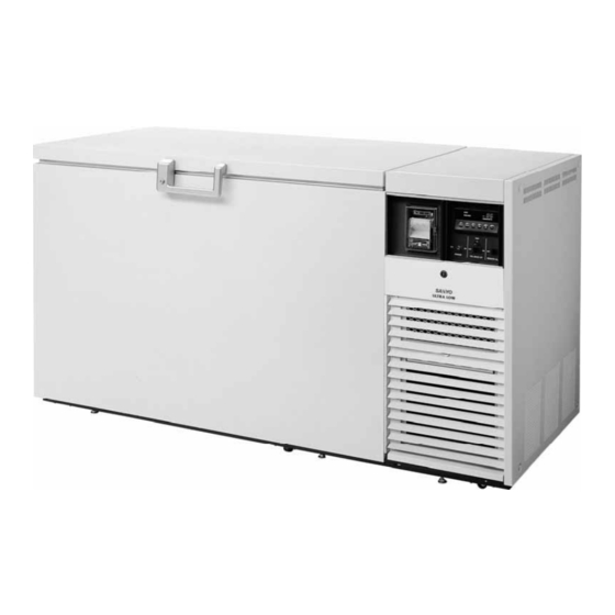
FREEZER COMPONENTS MDF-594... - Page 10 FREEZER COMPONENTS 1. Lock 2. Door: Hinged type. The door can be opened in any angle on the way to full open. 3. Magnetic door gasket: Seals the door and prevents leakage of cold air. 4. Inner lid: Serves as a means of reducing cold air leakage when the door is open. Remove the frost before it is accumulated too much.
-
Page 11: Control Panel
FREEZER COMPONENTS Control panel 12 11 MDF-594AT/ 794AT 1. Power switch (POWER): Power all functions except remote alarm and back-up system for AT type. BACK UP): AT type only. 2. CO Back-up switch (CO Back-up test switch (TEST): AT type only. 3. -
Page 12: Installation Site
INSTALLATION SITE To operate this unit properly and to obtain maximum performance, install the unit in a location with the following conditions: ■ A location not subjected to direct sunlight Do not install the unit under direct sunlight. Installation in a location subjected to direct sunlight cannot obtain the intended performance. -
Page 13: Installation
Extend the leveling feet by rotating them counterclockwise to contact them to the floor. Ensure the unit is level. MDF-594 Leveling foot 3. Fixing the unit Two fixtures are attached to the rear of the frame. Fix the frame to the wall with these fixtures and rope or chain. -
Page 14: Start-Up Of Unit
START-UP OF UNIT Follow the procedures for the initial and consequent operations of the unit. 1. Make sure that all the switches on the control panel, such as the power switch, battery switch, the back-up system switch (AT type only) are off. 2. -
Page 15: Chamber Temperature Setting
CHAMBER TEMPERATURE SETTING Table 1 shows the basic operation method. Perform key operations in the sequence indicated in the table. The example in the table is based on the assumption that the temperature is -75 Note: The unit is set at the factory that the chamber temperature is -80 Table 1. -
Page 16: Alarm Temperature Setting
ALARM TEMPERATURE SETTING This unit is provided with the high temperature alarm. The setting of high temperature alarm is 10 C or C (The setting value is 2 kinds.) higher than the setting of chamber temperature. The procedure in table 2 shows the sequence to set the high temperature alarm at 15 C higher than the setting of chamber temperature. -
Page 17: Setting Of Alarm Resume Time
SETTING OF ALARM RESUME TIME The alarm buzzer is silenced by pressing alarm buzzer stop key (BUZZER) on the control panel during alarm. The buzzer will be activated again after certain suspension if the alarm condition is continued. The suspension time can be set by following the procedure shown in the table 3 below. The example in the table is based on the assumption that the desired duration is 20 minutes. -
Page 18: Remote Alarm Terminal
REMOTE ALARM TERMINAL The terminal of the remote alarm is located at rear of the machinery room, upper side of the electric box. The signal is contact output. The recommended contact capacity is 2 A (DC 30 V) . a) Contact output : normal open connect with N.O. and COM. b) Contact output : normal close connect with N.C. - Page 19 • Fan motors are expendable supplies. Exchange them for about every 6 years. Contact Sanyo sales representative or agent at the time of replacement of the fan motor. (MDF-794 type has two fan motors.)
-
Page 20: Temperature Recorder (At Type)
TEMPERATURE RECORDER (AT type) The figure below shows the description of a temperature recorder. The temperature recorder is provided with model AT type. Time Temperature Warning indicator Recording indicator Pen holder lever Door Cartridge Feeding of chart 1. Open the door and let down the lever of the penholder; the pen point is apart from the chart. (Fig. 1) 2. - Page 21 The battery for back-up system is discharged when the back-up switch is kept on. ■ The additional felt pen or recording paper is available from Sanyo sales agency. ■ To stop the temperature recorder, remove the cell from the recorder. The back-up system can operate without recorder cell.
-
Page 22: Back-Up System (At Type)
CO gas cylinder to the joint of the back-up system. For this setting, consult with a qualified gas supplier or Sanyo sales agency. 2. After setting the liquid CO gas cylinder, operate the freezer until the chamber temperature reaches... -
Page 23: Routine Maintenance
ROUTINE MAINTENANCE WARNING Always disconnect the power supply to the unit prior to any repair or maintenance of the unit in order to prevent electric shock or injury. Ensure you do not inhale or consume medication or aerosols from around the unit at the time of maintenance. -
Page 24: Troubleshooting
Inquire at liquid carbon dioxide suppliers about its check, adjustment, installation, or move. Note: If the malfunction is not eliminated after checking the above items, or the malfunction is not shown in the above table, contact Sanyo sales representative or agent. -
Page 25: Replacement Of Battery
3 years. It is recommended that the battery is replaced ahead of time. For the replacement of the battery, contact Sanyo sales representative or agent. Location of a nickel-cadmium battery This unit is provided a nickel-cadmium battery for the power failure alarm. -
Page 26: Disposal Of Unit
DISPOSAL OF UNIT WARNING If the unit is to be stored unused in an unsupervised area for an extended period ensure that children do not have access and doors cannot be closed completely. The disposal of the unit should be accomplished by appropriate personnel. Always remove doors to prevent accidents such as suffocation. - Page 27 Waste Electrical and Electronic Equipment (WEEE) Directive-2002/96/EC (English) Your SANYO product is designed and manufactured with high quality materials and components which can be recycled and reused. This symbol means that electrical and electronic equipment, at their end-of-life, should be disposed of separately from your household waste.
- Page 28 DISPOSAL OF UNIT (French) Votre produit Sanyo est conçu et fabriqué avec des matèriels et des composants de qualité supérieure qui peuvent être recyclés et réutilisés. Ce symbole signifie que les équipements électriques et électroniques en fin de vie doivent être éliminés séparément des ordures ménagères.
- Page 29 Por favor, ajude-nos a conservar o ambiente em que vivemos! (Italian) Il vostro prodotto SANYO è stato costruito da materiali e componenti di alta qualità, che sono riutilizzabili o riciclabili. Prodotti elettrici ed elettronici portando questo simbolo alla fine dell’uso devono essere smaltiti separatamente dai rifiuti casalinghi.
- Page 30 Alstublieft help allen mee om het milieu te beschermen. (Swedish) Din SANYO produkt är designad och tillverkad av material och komponenter med hög kvalitet som kan återvinnas och återanvändas. Denna symbol betyder att elektriska och elektroniska produkter, efter slutanvändande, skall sorteras och lämnas separat från Ditt hushållsavfall.
-
Page 31: Specifications
Note •The battery for power failure alarm is an article for consumption. It is recommended that the battery will be replaced about every 3 years. Contact Sanyo sales agency at the time of replacement of the battery for recycling. • Fan motors are expendable supplies. Exchange it for about every 6 years. Contact Sanyo sales... - Page 32 Note •The battery for power failure alarm is an article for consumption. It is recommended that the battery will be replaced about every 3 years. Contact Sanyo sales agency at the time of replacement of the battery for recycling. • 2 fan motors are expendable supplies. Exchange it for about every 6 years. Contact Sanyo sales...
-
Page 33: Performance
PERFORMANCE Model MDF-594 / MDF-594AT Cooling performance Center part of freezing room; -86 C (Ambient temperature; +30 C, no load) Temperature Control range -20 to -86 Power source 220 V, 50 Hz 220 V, 60 Hz 230 V, 50 Hz... -
Page 34: Safety Check Sheet
CAUTION Please fill in this form before servicing. Hand over this form to the service engineer to keep for his and your safety. Safety check sheet 1. Freezer contents : Risk of infection: Risk of toxicity: Risk from radioactive sources: (List all potentially hazardous materials that have been stored in this unit.) Notes : 2. - Page 35 7FB6P101474001 (22 October 2007) 5-5, Keihan-Hondori 2-Chome Moriguchi City, Osaka 570-8677 Japan Recycled paper Printed in Japan...