Advertisement
Quick Links
Service Manual
Grundig Service
Hotline Deutschland...
...Mo.-Fr. 8.00-16.30 Uhr
Technik:
TV/SAT
0180/52318-41
VCR/LiveCam
0180/52318-42
HiFi/Audio
0180/52318-43
Car Audio
0180/52318-44
Telekommunikation
0180/52318-45
Fax:
0180/52318-51
Ersatzteil-Bestellannahme:
0180/52318-40
Telefon:
0180/52318-50
Fax:
POWER
TAPE 2 VCR
A
SPEAKERS
B
Zusätzlich erforderliche
Unterlagen für den Komplettservice
Additionally required
Service Manuals for the Complete Service
Service
Service
Manual
Manual
V 23
Sicherheit
Safety
Sach-Nr./Part No.
Sach-Nr./Part No.
72010-755.50
72010-800.00
SAT/TV
VOLUME
CD
PHONO
HIFI STEREO DISCRETE AMPLIFIER V23
HEADPHONES
VOLUME
HiFi
V 23
TUNER
TAPE
VCR
BALANCE
BASS
TREBLE
LOUDNESS
DEFEAT
LEFT
RIGHT
–
+
–
+
Btx * 32700 #
Sachnummer
Part Number 72010-755.50
Änderungen vorbehalten
Subject to alteration
Printed in Germany
VK233 1097
Advertisement

Related Manuals for Grundig V 23


Summary of Contents for Grundig V 23
-
Page 1: Grundig Service
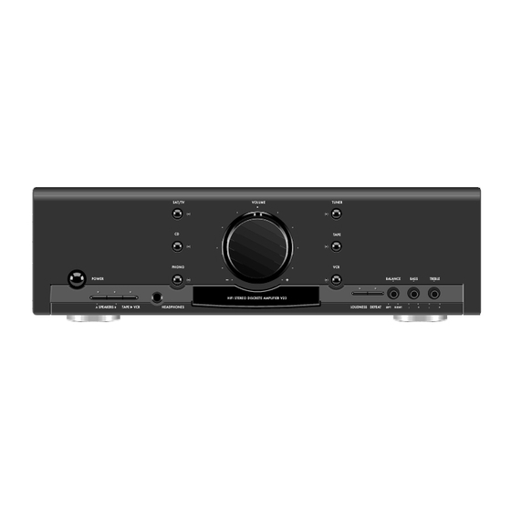
Service Manual HiFi V 23 Grundig Service Hotline Deutschland..Mo.-Fr. 8.00-16.30 Uhr Technik: TV/SAT 0180/52318-41 VCR/LiveCam 0180/52318-42 HiFi/Audio 0180/52318-43 Car Audio 0180/52318-44 Telekommunikation 0180/52318-45 Fax: 0180/52318-51 Ersatzteil-Bestellannahme: 0180/52318-40 Telefon: 0180/52318-50 Fax: SAT/TV VOLUME TUNER TAPE PHONO BALANCE BASS TREBLE POWER... -
Page 2: Table Of Contents
Meßgeräte / Meßmittel Test Equipment / Aids Digitalvoltmeter Digital voltmeter Beachten Sie bitte das GRUNDIG Meßtechnik-Programm, das Sie Please note the Grundig Catalog "Test and Measuring Equipment" unter folgender Adresse erhalten: obtainable from: GRUNDIG Instruments GRUNDIG Instruments Test- und Meßsysteme GmbH Test- und Meßsysteme GmbH... -
Page 3: Ausbauhinweise
V 23 Allgemeiner Teil / General Section Ausbauhinweise Disassembly Instructions 1. Gehäuse 1. Cabinet - 6 Schrauben herausschrauben (Fig. 1 und 2). - Undo 6 screws (Fig. 1 and 2). - Deckel abnehmen. - Remove cover. Fig. 1 Fig. 2 2. - Page 4 Allgemeiner Teil / General Section V 23 Fig. 3 Fig. 4 4. Netzteilplatte ausbauen 4. Removing the Power Supply Board - Rastung der Netztaste ausrasten. - Disengage the mains button. - Fuß unter dem Netztrafo ausbauen (Schraube , Fig. 3).
- Page 5 V 23 Allgemeiner Teil / General Section 6. Front zerlegen 6. Disassembling the Front - Front ausbauen (Pkt. 2). - Remove Front (para 2). - Laustärkeknopf abziehen und darunter befindliche Mutter lösen - Pull off volume knob and disengage the nut (Fig.
- Page 6 Allgemeiner Teil / General Section V 23 Notizen / Notes 1 - 6 GRUNDIG Service...
-
Page 7: Bedienhinweise
Dämpfung durch Textilien verursacht werden. – Haben Sie zwei Bandgeräte angeschlossen, angewählt. Stellung des Lautstärke-Einstellers. Dabei wird eine Konsequenz der Grundig können Sie von einem Gerät auf das andere Hinweis: Diese Funktionen sind nur ausführbar, der Klang dem menschlichen Gehör Umweltpolitik, die sich zum Ziel –... -
Page 8: Operating Hints
Die zu diesem Gerät beigelegte Fernbedienung kann sich einzelne Funktionen nicht mehr ausführen, sollten dos der Fernbedienung für die Tuner-Tasten zu aktivieren. den SAT/TV-Eingang angeschlossen ist). neben Geräten der Unterhaltungselektronik von Grundig, Sie die Batterien auswechseln. Zehnertastatur für Direkt-Anwahl von Stationen auch Fernsehgeräte, Satellitenempfänger und Video- y TV –... - Page 9 TXT/ – To change the information shown in the display. – For selecting next or previous satellite REAR - SURROUND - CENTRE e.g. one of the buttons. (not useful for Grundig CD players CD21/22/23) programmes. VOLUME VOLUME INSTALL – / + –...
-
Page 10: Abgleich
Abgleichvorschriften / Adjustment Procedures V 23 Abgleichvorschriften Meßgeräte: Digitalvoltmeter Abgleich Vorbereitung Abgleichprozedur Ruhestrom Kein Eingangssignal. Lautstärke auf Null. Gerät minde- stens 2 min warmlaufen lassen. Linker Kanal: Linker Kanal: ± Digitalvoltmeter zwischen Meßpunkte Al und Bl. Mit R516 auf 4,3mV 0,2mV einstellen. - Page 11 V 23 Schaltpläne und Druckplattenabbildungen / Circuit Diagrams and Layout of PCBs V 23 Schaltpläne und Druckplattenabbildungen / Circuit Diagrams and Layout of PCBs Schaltpläne und Druckplattenabbildungen / Circuit Diagrams and Layout of PCBs Eingangswählerplatte / Input Board Klangreglerplatte / Tone Control Board Lautstärkeplatte / Volume Board...
- Page 12 Schaltpläne und Druckplattenabbildungen / Circuit Diagrams and Layout of PCBs V 23 Schaltpläne und Druckplattenabbildungen / Circuit Diagrams and Layout of PCBs V 23 Eingangswählerplatte, Klangreglerplatte, Lautstärkeplatte / Input Board, Tone Control Board, Volume Board 0.40V page -0.25V 2.8V 0.40V 0.40V...
- Page 13 V 23 Schaltpläne und Druckplattenabbildungen / Circuit Diagrams and Layout of PCBs V 23 Schaltpläne und Druckplattenabbildungen / Circuit Diagrams and Layout of PCBs 10.7V -0.6V 16.7V -1.3V 7.3V -1.9V -0.6V 10.7V -0.6V page 16.7V -1.3V 7.3V -1.9V -0.6V page...
- Page 14 Schaltpläne und Druckplattenabbildungen / Circuit Diagrams and Layout of PCBs V 23 Schaltpläne und Druckplattenabbildungen / Circuit Diagrams and Layout of PCBs V 23 Audioplatte, Kopfhörerplatte / Audio Board, Headphone Board 40.8V 40.2V 1.4V 0.6V -0.6V -0.6V -1.4V page 40.8V 40.2V...
- Page 15 V 23 Schaltpläne und Druckplattenabbildungen / Circuit Diagrams and Layout of PCBs V 23 Schaltpläne und Druckplattenabbildungen / Circuit Diagrams and Layout of PCBs Audioplatte / Audio Board Kopfhörerplatte / Headphone Board GRUNDIG Service 3 - 9 GRUNDIG Service 3 - 10...
- Page 16 Schaltpläne und Druckplattenabbildungen / Circuit Diagrams and Layout of PCBs V 23 Schaltpläne und Druckplattenabbildungen / Circuit Diagrams and Layout of PCBs V 23 Trafoplatte / Transformer Board page 3-16 TO P503 AUDIO BOARD page 3-16 3 - 11 GRUNDIG Service...
- Page 17 V 23 Schaltpläne und Druckplattenabbildungen / Circuit Diagrams and Layout of PCBs V 23 Schaltpläne und Druckplattenabbildungen / Circuit Diagrams and Layout of PCBs Trafoplatte / Transformer Board P3T(red) P2T(gry) P1T(yel) T315mA 1655 1654 6606 5201 10 16 14 12...
- Page 18 Schaltpläne und Druckplattenabbildungen / Circuit Diagrams and Layout of PCBs V 23 Schaltpläne und Druckplattenabbildungen / Circuit Diagrams and Layout of PCBs V 23 Bedienplatte / Control Board page 3-11 page page page 3 - 15 GRUNDIG Service 3 - 16...
-
Page 19: Verdrahtungsplan
V 23 Schaltpläne und Druckplattenabbildungen / Circuit Diagrams and Layout of PCBs V 23 Schaltpläne und Druckplattenabbildungen / Circuit Diagrams and Layout of PCBs Verdrahtungsplan / Wiring Diagram GRUNDIG Service 3 - 17 GRUNDIG Service 3 - 18... - Page 20 Ersatzteilliste und Explosionszeichnung / Spare Parts List and Exploded View V 23 Ersatzteilliste und Explosionszeichnung / Spare Parts List and Exploded View V 23 Ersatzteilliste und Explosionszeichnung / Spare Parts List and Exploded View 0045 0046 0037 0036 0050 0057...
Need help?
Do you have a question about the V 23 and is the answer not in the manual?
Questions and answers