Table of Contents
Advertisement
Quick Links
Advertisement
Chapters
Table of Contents

Related Manuals for Panasonic FP-7818


Summary of Contents for Panasonic FP-7818
-
Page 1: Service Manual
ORDER NO. OED9909380B8 Service Manual Parts Manual Plain Paper Copier FP-7818/7824/7830 FP-7835/7845/7850 Staple Sorter FA-S620/660 System Console FA-DS72/82 © 1999 Matsushita Graphic Communication Systems, Inc. All rights reserved. Unauthorized copying and distribution is a violation of law. - Page 2 This manual was developed and is supplied to authorized servicing dealers by Panasonic Co. for the sole purpose of providing information necessary for the equipment’s proper support. It is intended that this information be confidential and may not be reproduced without prior written consent from Panasonic Co.
- Page 3 This manual dose not contain descriptions of PCB Connector and Signal Information and Sub Assemblies Operation which are discribed and unchanged in the FP-7718/7722/7728/7735/7742/7750 service manual. For those items not covered in this manual, please refer to the FP-7718/7722/7728/7735/7742/7750 service manual or PCB repaire manual.
-
Page 4: Table Of Contents
1.1 Specification ..................1-1 1.2 Features .................... 1-3 1.3 System Configuration ............... 1-4 1.4 Operation ..................1-6 (1) Special Effects Panel (FP-7818/7824/7830/7835) ...... 1-7 (2) Communications Monitor (FP-7818/7824/7830/7835) ....1-8 1.5 Component Location ................. 1-9 (1) Inner view .................. 1-10 (2) Fan/Motor Location .............. - Page 5 IV. Preventive Maintenance 4.1 Precautions for Periodic Maintenance Service ......... 4-1 4.2 Maintenance chart ................4-2 4.3 Cleaning Method ................4-4 4.4 Disassembly and Re-assembly ............4-7 (1) Multi-feed bypass ................ 4-8 (2) Paper feed unit ................4-11 (3) Developer unit ................4-14 (4) Fuser unit ..................
- Page 6 Caution: Danger of explosion if battery is incorrectly replaced. Replace only with the same or equivalent type recommended by the manufacturer. Dispose of used batteries according to the manufacture's instructions. For Sweden, and Denmark SPECIALSÄKRING: ENDAST AV APPARATFABRINKANTEN LEVERERAD SÄKRING FåR ANVÄNDAS. VARNING! Explosionsfara vid felaktigt batteribyte.
- Page 7 If you lose the fuse cover the plug must not be used until a replacement cover is obtained. A replacement fuse cover can be purchased from your local Panasonic Dealer. IF THE FITTED MOULDED PLUG IS UNSUITABLE FOR THE SOCKET OUTLET IN YOUR OFFICE THEN THE FUSE SHOULD BE REMOVED AND THE PLUG CUT OFF AND DISPOSED OF SAFELY.
-
Page 9: Introduction
11.Paper exit tray capacity 250 sheets 12.Paper weight Cassette : 16–24 lbs ( 60–90g/m Bypass : 15–30 lbs (55–130g/m 13.Special paper OHP,Label paper, Tracing paper (Through multi-feed bypass) 14.Continuous copying 1-999 reset to 1 (1-99 reset to 1 : FP-7818) - Page 10 AC120V 60Hz / AC220 - 240V 50Hz 21.Dimensions (W x D x H) 23.9" x 26.0" x 22.9" / 606 x 661 x 582 mm (23.9" x 26.0" x 18.1" / 606 x 661 x 479 mm : FP-7818) 22.Weight...
-
Page 11: Features
• Functional expansion through optional accessories Equipping with the system stand and LCC allows a high copy volume Maximum feed paper capacity FP-7818 2,250 sheets : four drawers + multiple sheert bypass FP-7824 2,800 sheets : five drawers + multipler sheet bypass... -
Page 12: System Configuration
Main Unit Sorter Paper drawer System console Cover 3000 Storage <Commonality of accessories> Accessories FP-7818 FP-7824 FP-7830 FP-7835 FP-7845 FP-7850 FA-DS72 System FA-DS82 console LCC ( FA-MA301 ) Number of drawer 1 + ADU 1 + ADU Copier paper feed... - Page 13 [ Comparison of specifications ] FP-7818 FP-7824 FP-7830 FP-7835 FP-7845 FP-7850 Warm up time ( sec.) First copy time ( sec.) Paper feed cassette 1+ADU 1+ADU System stand DS72 DS72 DS72 DS72 DS82 DS82 Copy speed Control panel design LCD display LCD display...
-
Page 14: Operation
1. 4 Operation • FP-7818/7824/7830/7835 Reset Key Energy Clear/Stop Interrupt Saverkey LEDGER LEGAL 1 2 3 LETTER 4 5 6 INVOICE 7 8 9 0 Recall Key Communications To recall the number Original Size of copies selected Monitor Keys during a copy run. -
Page 15: Special Effects Panel (Fp-7818/7824/7830/7835)
• Using i-ADF and ADU 2 in 1 (Except FP-7818/7824) mode • Using ADU Access 2:1 Copy (Except FP-7818/7824) User Preset • Using i-ADF OHP interleaving mode 2-Page copy/2 in 1 mode selection (2 in 1 : Except FP-7818/7824) Zoom Margin Shift Mode... -
Page 16: Communications Monitor (Fp-7818/7824/7830/7835)
(2) Communications Monitor (FP-7818/7824/7830/7835) FP-7818/7824 FP-7830/7835 STAPLE SORT LEDGER STACK LEGAL LETTER STAPLE LETTER SORT INVOICE STACK FP-7718 Indicator Indicator Adding Message Display Paper (FP-7830/7835) Toner Indicates procedures, functions Staple (Except FP-7818) maintenance, etc., Replacing Exposure Indicator Waste Toner Bottle... -
Page 17: Component Location
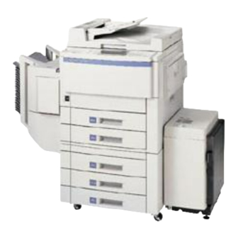
1. 5 Component Location ( Outer view ) Control Panel i-ADF Bypass Sorter FP-7818 Sorter System console FP-7824/7830/7835 LCD touch panel i-ADF (Except FP-7824) Control panel Right cover Front panel Sorter Bypass Paper feed cover FP-7845/7850 System console... -
Page 18: Inner View
(1) Inner view 6 7 38 8 9 10 11 12 Half-speed unit 20 Paper feed roller Full-speed unit 21 DFP roller Lens Position sensor 22 Pick-up roller Thermistor 23 ADU Paper feed roller AE Sensor 24 Corona cleaner Main motor 25 Transfer/Separation corona Lens unit 26 Drum... -
Page 19: Fan/Motor Location
(2) Fan/Motor Location Optics fan Mirror stepping motor Optics fan Optics drive motor Exhaust fan Lens stepping motor Developer Optics fan cooling fan Toner bottle Main motor motor Dust collecting Suction/Ozone ADU drive motor Lifting motor (FP-7850) (lower stage) ADU paper length guide motor (FP-7850) ADU paper width guide motor... -
Page 20: Sensor Location
(3)Sensor Location Mirror home position Platen cover angle AE (Automatic original Platen cover density sensor) open/close Original size Paper feed cover open/close Exposure lamp Toner bottle home position home position Lens home Toner level position Bypass paper size Paper exit Front cover Bypass paper open/close... -
Page 21: Solenoid/Clutch/Discharge Lamp Location
(4) Solenoid/Clutch/Discharge lamp Location Discharge lamp Separation solenoid Registration roller clutch Paper exit Middle roller clutch solenoid Paper feed clutch (FP-7850) Bypass pick-up solenoid Door switch Paper feed clutch (lower stage) ADU clutch (FP-7850) Power switch Pick-up solenoid (lower stage) Recycle solenoid (5) PCB Location Control panel 3... -
Page 22: Copy Process
1. 6 Copy Process –DC Charger Discharge lamp Blacking prevention Trimming Reduction Discharge Exposure Original Cleaning Developer Toner Separation Transfer Exit Fusing Paper feed Primary Charge: Image Exposure: Developing: Latent charge image(–) Illumination Charge corona Toner (+) Drum Magnetic Latent roller charge Drum surface... -
Page 23: Precautions On Set Up
1. 7 Precautions on Set Up Copy machine performance and the copy quality is subject to and dependant on environmental conditions. To maintain good performance, quality, and safe operation, observe the following precautions: 1) For safe operation and to avoid trouble do not install the system under the following conditions: •... -
Page 24: Precautions With Consumables
1. 8 Precautions with Consumables Photoreceptor drum • Do not touch the surface (with the hand or anything else). • Stand the drum with the drum gear up for storage. • Be careful not to smear with saliva, water, oil and so on. •... - Page 25 • There are normally no special problems with storage and transport in a cold climate but, store in a low humidity condition. Do not put supplies near heaters. 5) Safety and hygiene Toner has the property of easily being wind blown. Toner on skin does not cause any damage to health but, inhaling it is undesirable even if a powder is simply dust.
-
Page 26: Image Control Qualitative Reasoning Based Adaptive Controller
Section II Control Functions 2. 1 Image Control Qualitative Reasoning Based Adaptive Controller • Even if the toner density is at it's standard level, the copy image may vary with time depending on the characteristics of drum and the environmental variations. To prevent this change, the copy density sensor which is installed under the developer unit controls the image to stablize the copy image. - Page 27 • Qualitative Reasoning Based Adaptive Controller Qualitative Reasoning Based Adaptive Controller is adaptive control on the basis of quantative reasoning theory. While successively reasoning and learning the change of process characteristics regardless of environmental changes and the variations with time and the number of copies on the copier, the system reads the patch marks and determines the best values of exposure and surface potential to establish the best gamma curve for optimum copy quality.
-
Page 28: Toner Density Control
2. 2 Toner Density Control To keep toner density(toner carrier ratio) in the developer unit constant, the TDC sensor (toner density sensor) which is installed under the developer unit detects the amount of carrier in the developer unit to control the toner density. <Fundamentals>... - Page 29 2) Maintain standard toner density While checking the output voltage of the TDC sensor for every copy, control the timing of toner supply to the developer unit so that the output voltage is 2.5V at all times to keep the toner density constant. Check TDC sensor output voltage at copying (or mixing).
-
Page 30: Trouble Avoidance Mechanism
2. 3 Trouble Avoidance Mechanism When some malfunction happens, this mechanism allows regular copy operation without error conditions (service man call) (providing the malfunction does not affect the basic copying operation and the appropriate function is not selected). <Indication> Appropriate function selected Appropriate function not selected The selected function is unavailable, Normal indication of copying... - Page 31 <Self-recovery item> Item Error code Copier paper feed ( upper ) E2-01 Copier Paper feed ( lower ) E2-02 System stand paper feed ( upper ) E2-03 System stand paper feed ( middle ) E2-04 System stand paper feed ( lower ) E2-05 System stand paper feed timing E2-10...
-
Page 32: Toner Recycling System
2. 4 Toner Recycling System To maximize the number of copies which can be produced for each bottle, toner cleaned off of the drum needs to be returned to the developer for re-use. Under normal circumstances, the copy process can damage some toner. In addition, other undesireable materials may be cleared from the drum surface and mixed with re- useable toner (such as paper dust, etc.). -
Page 33: Re-Try Control For Paper Misfeed
2. 5 Re-try Control for Paper Misfeed • Copy paper should pass the paper feed sensor within a specific time after the paper feed clutch turns on. To reduce paper misfeeds due to a slipping paper feed roller, the paper feed clutch turns on again (re-try operation). •... -
Page 34: Sub Assemblies
Section III Sub Assemblies 3.1 Main Drive The driving mechanism of this machine is as follows. Main motor Fuser unit Pulley 1 Pulley 2 Transport roller Magnetic Bypass roller unit Drum Registration roller Paper feed unit Middle roller Middle gear Middle roller Paper feed unit (Lower stage) Name of motor... -
Page 35: Detecting Sheet Bypass Paper Size
(1) Detecting sheet bypass paper size • The paper size for the sheet bypass is detected by a matrix of sheet bypass paper size sensors which are installed on the sheet bypass tray. • When setting the paper in the sheet bypass tray and adjusting the paper guide, the matrix is as follows. -
Page 36: Developing
(2) Developing • The developer mixing unit contains developer which is a mixture of fine powder (non-magnetic toner) and fine ferrite carrier. • The developer is mixed by the transport screw and the mixing mill. The toner becomes charged ( + ) and the carrier becomes charged ( – ). The developer is magnetically stuck on the aluminum sleeve of the magnet roller, and the magnetic brush is formed. -
Page 37: Supplying Toner
(3) Supplying toner The Toner Hopper Unit supplies toner to the Developer Mixing Unit via the Reserve Tank, so toner addition is done in two stages, by turning the Toner Hopper Motor in either direction: Forward Direction: The bottle turns (via a spring clutch) to supply toner from the Toner Bottle to the Reserve Tank. -
Page 38: Toner Level Detection
(4) Toner level detection • When the toner level sensor in the toner hopper detects no toner remaining, and does not detect toner after continuously turning the toner bottle "Add toner" is displayed. The copier is disabled. The machine can be used after the user's key input. After lighting the no toner indication, the machine stops after 300 copies. -
Page 39: Temperature Control
(5) Temperature control The heat roller is provided with two halogen lamps (main heater lamp and sub heater lamp). The main heater lamp turns ON during warming up and copying operation. To control the maximum power consumption, the sub heater lamp turns ON during warming up and after release of pre-heat mode only in order to reduce the warming up time of fuser unit. -
Page 40: Automatic Detection Of Original Paper Size
(6) Automatic detection of original paper size • Opening the platen cover by approx. 30 degrees to insert the original, the platen cover angle sensor turns on and four original size detection sensors operate simultaneously. • The original size detection sensors consists of light emission unit and light reception unit. -
Page 41: Preventive Maintenance
Section IV Preventive Maintenance The periodic maintenance service is performed by machine cleaning and parts replacements. It is essential to perform these service activities properly for customer satisfacation. The purpose of this service is to maintain the machine performance and the copy quality. -
Page 42: Maintenance Chart
4.2 Maintenance chart 1) Replacement Maintenance cycle FP-7818/7824 : per 80,000 copies FP-7830/7835/7845/7850: per 240,000 copies Item Service Part number Q'ty per Maintenance cycle (x 1000) unit 80/120 160/240 240/360 320/480 400/600 Paper Paper feed roller FFPMA05411 feed DFP Roller... - Page 43 FFPMA0470 Replace at 1,200,000 copies (Except FP-7818/7824) Heat roller (FP-7850) FFPMA0590 Heat roller (FP-7845) FFPMA0566 Heat roller (FP-7830/7835) FFPMA0577 Heat roller (FP-7818/7824) FFPMA0574 Heat roller bearing FFPMQ0572 Heat roller gear FFPMF1057 Fuser entry guide (lower) FFPKF1308 Replace at 1,200,000 copies...
-
Page 44: Cleaning Method
4.3 Cleaning Method • Cleaning method for each PM service visit is shown below. - Page 45 Cleaning position Tool/solvent Work/precaution 1 Sheet bypass paper - Use IPA, if toner is stuck on the Cloth with transfer roller rollers. (As little as possible.) water / IPA - Do not use cleaning cotton. 2 Sheet bypass paper feed roller 3 Timing roller 4 Middle roller 5 Paper feed roller...
- Page 46 Cleaning position Tool/solvent Work/precaution 17 Mirror (No.1 ~ 6) Blower - Clean with soft touch, otherwise, brush / the mirror surface may get Glass damaged cleaning - Clean with soft paper and IPA as 18 Lens paper with required. 19 Original size detecting Blower - Clean the dust on the sensor sensor...
-
Page 47: Disassembly And Re-Assembly
4. 4 Disassembly and Re-assembly PM parts replacement procedure • The replacement procedure of PM parts is as shown below. The replacement cycle of PM parts is shown for the FP-7750/7742. (For other models, refer to the correct Service Manual.) Multi-feed bypass Fuser Unit... -
Page 48: Multi-Feed Bypass
Multi-feed bypass Item Part name Cycle 1 Pick up roller 120K 2 Paper feed roller 120K 3 DFP roller 120K 4 Torque limiter 1200K 5 Registration roller 1080K 6 Registration roller 1080K bearing 5, 6 7 Cleaning sheet 600K Caution Magnet clutch Hook Hook... - Page 49 1) Replacement of the pick-up roller/paper feed roller (1)Remove the screws and covers. (x 2) (2)Disconnect the harness. (3)Remove the bypass tray. Note: Remove right cover (2 screws). (1)Remove the touch ring. (2)Remove the paper stopper. (3)Remove the sensor lever. (4)Remove the touch ring.
- Page 50 3) Replacement of the registration roller and cleaning sheet 1) Remove the right cover and rear cover. 2) Open the front cover. a) Open the waste toner bottle cover and remove the bottle. b) Turn the toner hopper 180°. 3) Pull and turn the developer release knob. 4) Remove the drum unit.
-
Page 51: Paper Feed Unit
(2) Paper feed unit Part name Item Cycle 1 Paper feed roller 120K 2 Pick-up roller 120K 3 DFP roller 120K 4 Torque limiter 1200K 5 Middle roller 1080K 4-11... - Page 52 1) Replacement of the paper feed roller and the Pick-up roller 1) Remove the right cover and rear cover. 2) Open the copier paper feed cover. 3) Remove the paper feed cover stopper. Note: Move the stopper to the larger hole and remove.
- Page 53 2) Replacement of the DFP roller and the torque limiter 1) Conduct the procedure 1 and 2. 2) Remove the lower roller cover (2 screws) 3) Remove the touch ring. 4) Remove the DFP roller. 5) Remove the torque limiter. Note: Confirm the direction of the torque limiter when re-installing it.
-
Page 54: Developer Unit
(3) Developer unit Part name Item cycle 1 Cleaning blade 120K 2 Drum 120K 3 Blade side seal (F) 120K 3 Blade side seal (R) 120K 4 Corona 360K 5 Developer 120K 6 Spacer ring (F) 120K 6 Spacer ring (R) 120K 7 Toner dispersion 600K... - Page 55 1) Replacement of the cleaning blade 1) Open the front cover. 2) Move the toner hopper to front side. 3) Pull and turn the developer release lever and release the developer unit. (Refer to p. 4–8 step 4) 1) Remove the drum unit solenoid cover (1 screw).
- Page 56 2) Replacement of the Drum / Side seal 1) Conduct the procedure 1 and 2 and take the drum unit out. 2) Remove the drum cleaning blade tension spring (refer to P.4-13 step 4). Remove the front side screw on the drum shaft. 4) Remove the drum shaft.
- Page 57 4) Replacement of the developer 1) Conduct the procedure 1 and 2 2) Remove the developer unit and remove the mixer lid. 3) Dump the developer out of the unit. 4) Vacuum any developer on mag-roller and inside of the unit. 5) Remove the developer unit duct cover and clean inside of duct cover.
- Page 58 6) Replacement of the toner dispersion prevention cover/magnetic roller stopper • Conduct procedure 1 and 2 then pull out the developer unit. (1)Remove the screws (x 2). (2)Remove the toner dispersion prevention cover. (3)Remove the magnetic roller stoppers (front/rear) and replace the magnetic roller.
-
Page 59: Fuser Unit
(4) Fuser unit Item Part name Cycle 1 Cleaning web roller 120K 2 Web pressure roller 1200K 3 Fuser lamp 240K 4 Heat roller 360K 5 Heat roller bearing 600K 6 Insulating bushing 360K 7 Heat roller gear 600K 8 Thermistor 240K 9 Separation finger (upper) - Page 60 1) Replacement of cleaning web/web pressure roller (1) Open the front cover. (2) Swing the toner hopper to the right. (3) Remove the fuser unit manual paper feed knob. (1 screw reverse threaded) (4) Remove the front cover. a) Remove the band. b) Slide out the hinge pins.
- Page 61 2) Replacement of the fuser lamp/heat roller/heat roller bearing/insulating bushing/ heat roller gear • Conduct procedure 1and 2. (1)Remove the screws (x 4) (2)Remove the heat insulating cover. Note: Either loosen pressure screws (x 2) or install fuser shipping screws (x 2). (1)Remove the springs.
- Page 62 3) Replacement of the thermistor • Conduct procedure 5. (3)(4) Remove the screw. (5)Remove the thermistor. • Replace the thermistor. SV507 4) Replacement of the separation finger (upper/lower) (1)Open the fuser exit cover. (2)Remove the screws (x 2). (3)Remove the separation finger (upper) bracket.
- Page 63 (1)Remove the spring (x 2). (2)Turn the separation fingers and remove them (x 5). SV506 5) Replacement of the pressure roller/roller bearing • Remove the heat roller (refer to step 5 to • Remove the separation finger upper/lower brackets (refer to 10 and 12). Mark the current height adjustment to use as a reference during re-assembly.
-
Page 64: Optics Unit
(5) Optics unit Item Part name Cycle 1 Exposure lamp 120K 2 Filter A 120K 2 Filter B 120K 3 Optics filter 120K 4 Full speed unit drive belt 5 Half speed unit drive belt 6 Optics drive belt : As required 4-24... - Page 65 1) Replacement of the exposure lamp Remove upper covers (left/right). (1)Remove the screws (x 3). (2)Remove the original guide. (3)Remove the platen glass. (4)Move the full speed unit to the right. SV601 (1)Remove the screws (x 2). (2)Remove the main reflector. Remove the exposure lamp and replace 4-25...
- Page 66 2) Replacement of filter A and B. Replacement of the optics fan filter • Conduct the procedure 1. Remove both left and right copier side covers. • Peel off the dust prevention filter and replace it with new one. 4-26...
- Page 67 3) Replacement of the optics motor belt/full-speed unit drive belt/half speed unit drive belt (1)Remove the platen cover (or ADF/i-ADF if installed). (2)Remove the copier front cover (refer to page 4-18 step 1). (3)Disconnect the lattice connectors of any options (System Console and LCC). (4)Remove the rear cover (7 screws).
- Page 68 Remove the left side control panel ass’y bracket. (1 screw). (1)Remove the ADF lattice connector bracket (5 screws). (2)Remove the optics motor tension spring. (3)Remove the left ADF hinge receiving bracket/key counter receptacle bracket (3 screws). (4)Remove the optics drive motor (3 screws). SV630 (5)Remove the optics drive motor belt.
- Page 69 Move the full-speed unit to right until it stops. (1)Remove the 2 screws on the full-speed unit support (each side). (2) Remove the full-speed unit belt fixing plate (each side). (1)Loosen the four idler pulley brackets (2 screws each). (2)Remove the four optics drive belt tension springs.
- Page 70 Disconnect the drive belts from both sides of the half-speed unit. Loosen the hex screws and remove the E rings in the optics drive shaft pulleys (each side). (1)Remove the E rings (each side). (2)Remove the bearings (each side). (3)Slide the optics drive shaft to the rear, and remove it.
- Page 71 Connect the full-speed unit drive belt (1) Install the belt fixing plate on the full-speed unit drive belt (each side). (2) Move the full-speed unit to right until it stops. (3) Tighten screws on the full-speed belt fixing plate. (each side) Connect the half-speed unit drive belt (1) Move the half-speed unit to right until it stops.
-
Page 72: Automatic Duplex Unit (Adu)
(6) Automatic duplex unit (ADU) Item Part name Cycle 1 Paper feed roller 2 Storage roller 3 F/R mylar 4 Paper feed pad 5 DFP roller 4-32... - Page 73 1) Replacement of the paper feed roller/storage roller/F/R mylar/feed roller pad (1) Pull out the ADU until it stops. (2) Remove the upper cover (2 screws). (3) Lift the transport guides (1 and 2). (1) Remove the screws (x 2). (2) Remove the stopper plate.
- Page 74 • Conduct procedure 1 and 2. • Peel off the paper feed pad and replace Replacement of the DFP roller • Conduct procedure 1. (1)Remove the screws (x 2). (2)Remove the DFP roller block. (1)Remove the touch rings (x 2). (2)Remove the bearing.
-
Page 75: Main Body
(7) Main body Item Part name Cycle 1 Corona cleaner 120K 2 Transfer wire 120K 3 Separation wire 120K 4 Ozone filter 240K 5 Ozone filters 240K 6 Dust collecting filter 240K (Main body) 7 Transfer chager 360K 4 7 3 1 2 8 Discharge lamp 240K 4-35... - Page 76 1) Replacement of the charger wire/wire cleaner felt (1)Open the front cover. (2)Turn the transport lever and lower the transport unit. (3)Press down the transfer charger and draw it toward you. • Remove the transfer corona. (1)Remove the paper guide. (2)Remove the charger cover.
- Page 77 2) Remove the suction fan and the ozone filter to replace them with new ones. (1)Remove the rear cover. (2)Replace the ozone filter. (Rear side) (Left side) Ozone filters (3)Replace the filters. • Open the front cover. • Remove the exit cover. (2 screws, more if sorter-equipped).
-
Page 78: Troubleshooting
V. Troubleshooting 5.1 Service Mode In Service mode, the technician can check for abnormalities in the copier so the copier can always operate normally. The input/output of major components in every section can be checked. To select the service mode The service mode is selected when USER PRESET, Multi-Copy key 3 and Original Size A3 keys are simultaneously pressed, then F1 will appear in the display. -
Page 79: Service Mode Procedure
(2) Service mode procedure F1 appears in the display when the service mode is first turned ON. Multi- Mode Copy Item Function Remarks Display When the Print key is pressed, It stops when the Clear/Stop check all displays light up. key is pressed. - Page 80 Multi- Mode Copy Item Function Remarks e. Repeat procedures b) and d). 4. 2 sided original, 1 sided copy Single mode. sheet a. Select the 2 sided original, 1 copying sided copy mode. b. One sheet is copied normally when the Print key is pressed. c.
-
Page 81: F4 Mode
(3) F4 mode 1) Input check. Set the copier to service mode and press Multi-Copy key “4”. Press Print key. Select desired code number with Multi-Copy key. Press Print key. Check arrow mark on the touch panel display. Press Clear/Stop and User Preset key to escape service mode. Code Function Condition... - Page 82 Code Function Condition Message display a) Sheet bypass paper detecting Paper is not detected. sensor b) Sheet bypass paper size Ledger/A3 detection sensor Legal/B4-FLS Letter/A4 Letter R/A4R Invoice/A5 c) Platen open/close sensor Platen is open. d) Platen angle sensor Platen is open more than 30 degrees.
- Page 83 Code Function Condition Message display a) Exhaust fan motor 1 Motor is locked. b) Exhaust fan motor 2 Motor is locked. c) Optics fan motor 1 Motor is locked. d) Optics fan motor 2 Motor is locked. e) Optics fan motor 3 Motor is locked.
- Page 84 Code Function Condition Message display a) System console motor Motor is locked. signal b) System console paper feed Cover is closed. cover sensor c) Paper detection sensor 3 Paper is not detected. (System console lower paper tray) d) Paper limit sensor 3 Paper is over stocked.
- Page 85 Code Function Condition Message display a) LCC detecting sensor 1 LCC is not installed. b) LCC door open/close sensor Door closed. c) LCC detecting sensor 2 LCC is pulled out. d) LCC paper tray lower limit Paper tray is beyond the sensor lower limit.
- Page 86 Code Function Condition Message display For FA-S575 a) Motor clock sensor Signal is detected. b) Bin ass'y upper/lower limit switch Bin is beyond the upper limit or beyond the lower limit. c) Cable safety switch Cable is not loose. d) Bin ass'y position sensor 2 Bin ass'y position is not placed correctly.
- Page 87 Code Function Condition Message display For FA-S680 a) Bin paper detecting sensor Paper is detected. b) Paper pass sensor Paper is detected. c) Staple detecting sensor Staple is detected For FA-S680 a) Stapler cam sensor Cam in home position. b) Stapler swing home position Stapler swing in home position.
- Page 88 Lamp turns off after 2 seconds. Ozone/suction fan, developer unit cooling When CN8-1 is +24V, ozone/suction fan rotates. fan (Except FP-7818) and dust collecting When CN8-2 is +24V, dust collecting fan rotates. When CN8-7 is +24V, developer cooling fan rotates.
- Page 89 Lift motor 1 When CN603-1 is +24V, motor rotates, (When duplex unit is not installed.) lifting up (together with upper limit control.) (Except FP-7818) Paper feed clutch 1 When CN610-3 is +24V, clutch operates. (When duplex unit is not installed.)
- Page 90 Option paper feed drive motor When CN602-7 is +24V, motor rotates. LCC paper feed solenoid When CN564-2 is +24V, solenoid operates. (Except FP-7818/7824) LCC paper feed tray lift (up) When CN563-1 is +24V, motor rotates, (Except FP-7818/7824) lifting up (together with upper limit control.)
- Page 91 Code Item Function Paper feed motor forward rotation The motor rotates forward. (FA-A888) Paper feed motor reverse rotation The motor rotates reverse. (FA-A888) (High speed) Paper feed motor reverse rotation The motor rotates reverse. (FA-A888) (Middle speed) Paper feed motor reverse rotation The motor rotates reverse.
- Page 92 Code Item Function Staple ready indicator (LED) The ready indicator lights up. (only Staple Sorter) Stapler swing motor The swing motor drives in and out. (only Staple Sorter) 5-15...
-
Page 93: F5 Mode Copier Function Programming
7: No energy saver timer 4–6 Not used Message display 0: Japanese 5: Spanish language change 1: English 6: Swedish (Except FP-7818/7824) 2: German 7: Finnish 3: French 8: Dutch 4: Italian 9: Portuguese Not used Fuser lamp phase 0: Zero cross control... - Page 94 1: Sorter installation automatically discriminated System console 0: Cancellation of system console 1: System console installation automatically discriminated 0: Cancellation of LCC 0 (FP-7818/7824) (3000 sheet paper tray) 1: LCC installation automatically 1 (FP-7830/7835/ discriminated 7845/7850) Not used Copy density sensor read*...
- Page 95 Code Item Function (Factory setting) Total copy count 0: Does not count up (Except FP-7818) 1: Count up Checking double feed by comparison between in/out copies. Not used Skyshot mode 0: not change registration void position (Using ADF) 1: change registration void position...
- Page 96 0: Full size setting 1: Reduction Auto original size 0: No detection - Priority (Manual key LED lit) 0 (FP-7818/7824) detecting sensor 1: Detection - Priority (Manual key LED off) 1 (FP-7830/7835/ 2: Manual key status LED lit/off held in...
- Page 97 Code Item Function (Factory setting) Preventive maintenance 0: No call 10 (FP-7818/7824) 1: 1.5K 2: 2.5K 3: 5K 12 (FP-7830/7835/ 4: 10K 5: 15K 6: 20K 7845/7850) 7: 30K 8: 40K 9:60K 10: 80K 11: 90K 12: 120K 13: 160K...
- Page 98 Code Item Function (Factory setting) Check size M2 X Length of paper vertical position to paper feed direction Factory use size unit change 0: AB, Janpanese 1 (for American) 1: inch 2 (for European) 2: AB, European 96-97 Not used Factory use paper size sensor 0: Yes change 1: No...
- Page 99 To Clear the Service Call indicator Re-input the F5-70 and F5-73. Set the copier to service mode and press Multi-Copy key “5” Press Print key. Scroll the display menu until code number 70 is indicated with arrow keys ( then touch “70” key. Touch desired PM cycle key and OK key.
-
Page 100: F6 Mode Adjustment And Programming
(5) F6 mode Adjustment and programming Set the copier to service mode and press Muiti-Copy key “6”. Press Print key. Select desired code number with touch panel display and touch the OK key. If you wish to select other code number, scroll the menu with arrow keys ( The display will indicate memorized number. - Page 101 Code Item Function Remarks Copy paper registration After 04 is adjusted, delay 0.425mm *same as F6-04 detecting timing time is adjusted from (FP-7850/7818) timing roller clutch ON. 0.375mm (FP-7845) 0.525mm (FP-7824/7830/7835) (–30 to +20) (+): Delayed (–): Advanced LED array synchronized After 04 is adjusted, 0.425mm timer for trimming function...
- Page 102 Toner recycle switch Adjustment of toner density 19.5mV (Except judgment level sensor judgment level (–10 to +10) FP-7818/7824) (Recycle or collection) White density Adjustment of standard –30 to +40 adjustment* white density level* Black density Adjustment of standard –99 to +99...
- Page 103 (–50 to +50) (FP-7850/7845) registration roller of 0.4mm (FP-7835/ system console. 7830/7824/7818) Paper loop same as F6-41 1.25ms. 0.7mm LCC (Except FP-7818/7824) (–50 to +50) (FP-7850/7845) 0.4mm (FP-7835/7830) Paper feeding Adjustment of registration 10.0ms. 5.4mm (ADU) timing (–50 to +50)
- Page 104 0.7mm with A888 (2 in 1 mode) (FA-A888) interval timing (–16 to +8) Registration width guide Adjustment of registration 0.39mm (Except FP-7818) standard position (Duplex) width guide position (–10 to +10) Registration length guide Adjustment of registration 0.31mm (Except FP-7818)
- Page 105 Code Item Function Remarks 75-79 Not used Automatic compensation Set by Qualitative –81 to +92 value (Read only) Reasoning Based Adaptive 0.18V Exposure voltage Controller Not used Automatic compensation Set by Qualitative –92 to +55 value (Read only) Reasoning Based Adaptive 2.28V Grid voltage Controller...
-
Page 106: F7 Mode Electronic Counter
(6) F7 mode electronic counter Read procedure Set the copier to service mode and press Multi-Copy key “7”. Press Print key. Select the desired code number with Multi-Copy key. Indicates memorized count in the electric counter. Press Clear/Stop and User Preset key to escape service mode. Code Item Function... - Page 107 Code Item Function System console lower Total count of upper stage of optional system console. paper drawer count LCC count Total count of optional LCC (3000 sheet paper drawer) Copier upper paper drawer Total count of copies from upper paper drawer of the copier. count NOTE: When the duplex unit is installed to/upper stage of (When duplex unit is not...
-
Page 108: F8 Mode Copier Operation Adjustment
100% and 200% copies. Procedure: a) Position the Panasonic Test chart-53/54 on the platen glass. b) Press the Print key. Measurement input for adjusting the This function measures the registration that was copied original registration using "01". - Page 109 Code Item Function h) This adjustment may cause the factory setting of F6- 04 to change, so check the F6-04 setting once more. If it has changed, transfer the revised value the memory sheet. i) After completing this adjustment, check F6-05 once more.
-
Page 110: F9 Telephone# Input
Code Item Function Not used Black density sensor reference level ( Factory use only / Need special fixtures ) adjustment ( Factory use only ) Black density sensor output gain This adjustment should be performed when installing adjustment the copier, cleaning/replace black density sensor or replacing the drum. -
Page 111: Self-Diagnostics/Machine Malfunctions
5.2 Self-diagnostics/Machine Malfunctions The self-diagnostic functions detect troubles in important components of the copier. When any trouble occurs, the copier is stopped. User error NOTE: XXXX will appear in message display. Error Message Item See page code INSERT KEY Key counter failure (option) or 4-34 Access code number was not INPUT IDENTIFICATION... - Page 112 Error Message Item See page code SORTER FULL-EMPTY If too many copies in bin or 4-37 PRESS MODE KEY too many bins selected. Remove copies and press the each sorter mode key on the touch panel. Not ready (Red LED flashes) Power saving ---------- The ready indicator will light and the other displays are...
- Page 113 (1) U0: Key counter failure or Access code number was not input *The copier does not indicate READY TO COPY when the key is inserted. Is the key inserted correctly? Re-insert the key. Is CN119-2 connected to CN-2? CN119-2, 4 of the CPU is defective. Is CN119-4 contact to CN-4? The key counter connection is defective.
- Page 114 (5) U6: Copier paper feed cover failure *The copier does not indicate READY TO COPY when the copier paper feed cover is closed. Is the paper feed cover closed securely? Close the paper feed cover securely. Does CN5-7, 9, 11 (output signal of CPU) Check DC5V of the tray detecting sensor.
- Page 115 (9) U12: Sorter with stapler *When the stapler mode is selected, and a staple cartridge is not inserted. (10) U13: Toner level detection *"U13" does not reset after replacing the toner bottle. Is the toner caked in the bottle? Shake the toner bottle well. Change the toner bottle.
- Page 116 (15) oF: Sorter bin capacity failure *Too many copies in at least one bin or too many bins selected. Did the number of copies Remove copies and press the Sorter mode exceed the bin capacity? select key. 5-39...
-
Page 117: Paper Jam
Paper Jam read Condition position code The registration roller paper pass sensor does not detect paper within a predetermined time after sheet bypass paper feed roller starts rotating. The copier upper paper feed unit paper pass sensor 1 does not detect paper within a predetermined time. - Page 118 read Condition position code Paper feeding from copier lower stage: The copier lower stage paper pass sensor 2 is detecting paper within a predetermined time after first detecting paper. Paper feeding from optional system console upper stage: Upper stage paper pass sensor 1 is detecting paper within a predetermined time after first detecting paper.
- Page 119 read Condition position code Transport operation for duplexing The duplex unit paper pass sensor 1 does not detect paper within a predetermined time after copier paper exit sensor detected paper. Transport operation for duplexing D, E The duplex unit paper pass sensor 1 is detecting paper within a predetermined time after sensor detected paper.
-
Page 120: Machine Error
Machine error The machine system will detect problems in important areas of the copier. When any problems occurs the copier stops. Error codes indicate the mode number and code number which are alternately displayed in "Digit" display area of touch screen. When there is trouble in any part of the copier, the "MACHINE ERROR TURN POWER SW OFF/ON"... - Page 121 E3: Developer unit and Hopper unit error Code Function Refer page E3-01 Toner bottle motor rotation 5-50 E3-03 Toner density sensor gain 5-50 E3-10 High voltage power supply leak (1) 5-51 E3-11 High voltage power supply leak (2) 5-51 E3-20 Main motor rotation 5-51 E3-21...
- Page 122 E7: Optional unit error *These errors are indicated when options are installed. Refer to Optional Unit Service Manual. Code Function Refer page E7-01 Sorter bin movement Sorter Service E7-03 Transport belt motor failure Manual E7-06 Stapler drive motor failure E7-07 Tamper drive motor failure E7-10 ADF main motor rotation...
- Page 123 E1-01: Optical unit scan drive When the lamp unit scanner motor drives to the optics home position sensor and is not detected within a predetermined time. Does the lamp unit move when the power Lamp unit scanner motor connector is shorted switch is turned ON? or broken.
- Page 124 E1-21: Mirror ratio drive When the mirror stepping motor drives to the mirror home position sensor and is not detected within a predetermined time. Does the mirror unit move when the Mirror stepping motor connector is shorted or power switch is turned ON? broken.
- Page 125 E1-40: Optics fan motor (1) rotation E1-41: Optics fan motor (2) rotation E1-43: Optics fan motor (4) rotation A lock signal is detected when the fan motor is rotating. Is DC24V, detected on CN 106-9, 12 or LVPS is defective. CN 107-3 (on LVPS PCB)? Connector is shorted or broken, Harness is defective.
- Page 126 E2-06: Optional LCC lift operation (UP) E2-07: Optional LCC lift operation (DOWN) When the lift motor drives up and down, the upper and lower limit switch are not detected within a predetermined time. Is lift motor sound detected? Check the upper limit sensor signal. Canged: CPU PCB is defective.
- Page 127 E3-01: Toner bottle motor rotation When the toner bottle motor drives to the toner bottle position and the toner bottle home position sensor is not detected. Does the toner bottle motor rotate Bottle motor connector is shorted or broken in manual toner addition mode? Bottle motor drive mechanism is defective.
- Page 128 E3-10: High voltage power supply leak (1) When a leak is detected from the high voltage power supply charge/transfer corona. Is the charge/transfer corona dirty? Clean the charge/transfer corona. Does the ground terminal float Tighten screw(s) on the ground terminal of from the copier frame? HVPS PCB or HVPS bracket.
- Page 129 E3-21: Dust collection fan motor rotation E3-22: Exhaust fan motor rotation E3-23: Suction fan motor rotation When the fan motor is rotated or stopped, fan motor rotation signal is/not detected. Is DC24V detected on CN8-1, 2 or 7? Fan motor connector is shorted or broken. fan motor is defective E3-30: Discharge lamp When the discharge lamp does not turn ON, or the fan motor fails to rotate when the...
- Page 130 E3-50: Transfer cleaner operation When the transfer cleaner motor drives, the transfer cleaner home position sensor is not ON/OFF within a predetermined time. Is the wire cleaner felt Does the wire cleaner felt connect to at the home position sensor? the corona rail slider? a) Turn the transport lever and lower the transport unit...
- Page 131 E4-10: Exhaust fan motor (1) rotation E4-11: Exhaust fan motor (2) rotation E4-12: Exhaust fan motor (3) rotation A lock signal is detected when the fanmotor is rotating. Is DC24V detected on CN106-3, 6 or LVPS is defective. CN107-6 (on LVPS PCB)? Connector is shorted or broken.
- Page 132 E5-04: Vo (+10V) line When the power switch is turned on, DC10V is not detected. Is DC24V detected on between (IC16, IC9 or IC13) CPU PCB CN1-8 and 9? E5-10: +5V (for Power saving mode) When the power saving mode is operated on and DC5V power supply is not 0V, The E5-10 is indicated just moved power saving mode.
- Page 133 E5-41: Registration timing control circuit abnormal When the copier stops, the optics scan and registration drive start driving or when the copier is operated, the optics scan and registration operating are not driven within a predetermined time. IC5 on CPU PCB is defective. E5-42: Total counter connection When the total counter is disconnected.
- Page 134 E6-04: Paper width home position detecting sensor When the paper width motor drives to home position, paper width home position detecting sensor is not sensed within a predetermined time. Does the paper width motor rotate? Check paper width home position detecting sensor output PSWSN(CN-2) Changed: Duplex unit control PCB is defective.
-
Page 135: User Preset Mode
5.3 User Preset Mode Regarding the operation procedure, please refer to the operating guide. (Factory Code Item Function setting) UP-00 Paper size (copier and System Refer to example Copier: Console) Ledger/A3 System: Not setting UP-01 Paper size priority 0: A4R, LETTER R 1: B4, LEGAL 2: A4, LETTER 3: A3, LEDGER 4: INVOICE, A5... - Page 136 8: Dutch 9: Portuguese UP-25 Auto selection 0: None prohibition paper tray (1) 1: Copier (upper) 2: Copier (lower) (Except FP-7818) 3: System console (upper) 4: System console (middle) 5: System console (lower) 6: LCC (Except FP-7818/7824) 7: Sheet bypass UP-26...
- Page 137 (Factory Code Item Function setting) UP-34 Indicate the access code number of Press the Access key and input the a specific department. code number. Changing the access code number Press the Access key and input the of a specific department. code number.
-
Page 138: Unpacking/Installation
VI. Unpacking/Installation 6. 1 Installation Requirements Make sure machine is properly leveled from left to right and from front to rear (use small carpenter level). The mains plug on this equipment must be used to disconnect mains power. Please ensure that the socket outlet is installed near the equipment and shall be easily accessible. -
Page 139: Installation Procedure
6.4 Installation Procedure • Remove the external packing/protection materials. • Remove the shipping tape from the copier. • Save the shipping materials for future use (Transport of copier) Location Shipping material/Procedure Check 1. Optical unit (1) Remove the original guide plate. (3 screws) (2) Remove the optical unit shipping brackets (front/rear) (1 screw... - Page 140 Location Shipping material/Procedure Check Paper transport unit (1) Open the front cover. (2) Remove the shipping tape. Tape Fuser unit (1) Open the paper exit door. (2) Open the fuser exit guide plate. (3) Remove the fuser pressure release screws. (2 screws) (4) Close the fuser exit guide plate.
- Page 141 Location Shipping material/Procedure Check Pour the developer into the unit (1) Remove the developer unit lid. (2) Pour the developer evenly into the unit. Note: Pour in the entire bottle of developer, after shaking it well. (3) Reinstall the developer unit lid. (4)-1.
- Page 142 Location Shipping material/Procedure Check Turn the power switch ON TDC adjustment (1) Press the “User Preset”, “Ledger/ A3 of Original Size” and “3” keys simultaneously to enter the F mode. (2) Press the “8” key to enter the F8 mode. (3) Press the “Print”...
- Page 143 Location Shipping material/Procedure Check Toner bottle insertion (1) Open the front cover. (2) Take a fresh bottle of toner and shake it 10 to 15 times. Hopper (3) Swing the toner bottle hopper open 90 degrees. (4) Remove the toner bottle cap. (5) Insert the toner bottle into the hopper unit and turn it clockwise.
-
Page 144: Adjustment
6.5 Adjustment Location Shipping material/Procedure Check Exposure standard adjustment (1) Enter the F6 mode. (2) Confirm F6-11, 12, 17, 18 and 19 to “0”, and change as necessary. (3) Enter the F2 mode and set the exposure to the center position in the Document mode. - Page 145 Location Shipping material/Procedure Check Side to side adjustment Screw 1. Sheet bypass tray (1) L o o s e n a d j u s t i n g s c r e w s . (2 screws) (2) Move the adjusting plate to the front or rear accordingly.
- Page 146 Location Shipping material/Procedure Check 3. Side to side adjustment (Duplex) (1) Pull the duplex unit tray out until it stops. (2) Loosen the four screws of the front cover. (3) Move the front cover as required, then tighten the screws. Note: Move the front cover evenly.
-
Page 147: White Density Adjustment
6.6 White Density Adjustment (When replacing the original guide for FA-A505) (1) Check the rank of sensor mark sheet back side of the original guide. (2) Select the F6 mode. (3) Press “2” and “8” keys to enter F6 mode code “28” then press “Print” key. (4) Enter the new content according to the rank of sensor mark sheet. - Page 148 FP-7818 / 7824 / 7830 / 7835/ 7845 / 7850 Parts Manual Contents/Index 1. Covers .................. 1 – 3 2. Frame ................... 4 – 13 3. Optics ................... 14 – 16 4. Toner Hopper Unit ..............17 5. Developer Section ..............18 6.
- Page 149 It is intended that this information be confidential and may not be reproduced without prior written consent from Panasonic Co. 5. Panasonic Co. reserves the right to change any information enclosed herein without prior notification. (This includes, but is not limited to, parts pricing and availability, and text.) 6.
- Page 150 For Japan FP-7830 FP-7835 PM703...
- Page 151 Cover Ref. Q'ty Per Com- Part No. Description Remarks Unit FFPXB08H00 Top Cover, Right Ass'y FFPGC0154 Platen Glass (7818/7824/7830/7835) FFPGC0202 Platen Glass (7830DC/7835DC/7835MX) FFPKN0271 Glass Cushion FFPPA04055 Paper Size Plate (for North America) FFPPA04065 Paper Size Plate (except North America) FFPNA0612 Top Cover, Left FFPHK09361...
- Page 152 For Japan FP-7830 FP-7835 PM703...
-
Page 153: Covers
Covers Ref. Q'ty Per Com- Part No. Description Remarks Unit FFPND0176 LED Cover (7824 except North America) FFPLB0234 Start Button Key Top FFPWB05758 PCB Control Panel 2 (7830/7835) FFPWC1580 CT Cable 3 (7830/7835) ==Not used== ==Not used== ==Not used== FFPGB0022 Filter A FFPLB0169 Control Panel Key Top 2... - Page 154 PM703...
- Page 155 Covers Ref. Q'ty Per Com- Part No. Description Remarks Unit FFPXB08H00 Top Cover, Right FFPGC0202 Platen Glass FFPKN0271 Glass Cushion FFPPA04055 Paper Size Plate (for North America) FFPPA04065 Paper Size Plate (except North America) FFPNA0612 Top Cover, Left FFPHK09361 Sensor Mark Sheet FFPNA0614 Top Cover, Rear FFPNA07702...
- Page 156 PM704...
- Page 157 Covers Ref. Q'ty Per Com- Part No. Description Remarks Unit FFPNA06102 Right Cover (except 7818) FFPNA06192 Right Cover (7818) FFPKE1021 Cover, Open/Close (except 7718) FFPNA0629 Cover, Open/Close (7818) FFPKE0999 Inner Cover 3 FFPKE1032 Inner Cover FFPKE09983 Inner Cover 2 FFPXB05R00 Front Cover (7818) FFPXB05R10 Front Cover (7824)
- Page 158 PM704...
- Page 159 Covers Ref. Q'ty Per Com- Part No. Description Remarks Unit FFPTD0936 Operating Guide (Einglish for North America) FFPTD0937 Operating Guide (French for Canada) FFPTD0938 Operating Guide (Einglish ex. North America) FFPTD0939 Operating Guide (German) FFPTD0940 Operating Guide (French) FFPTD0941 Operating Guide (Dutch) FFPTD0942 Operating Guide (Italian) FFPTD0943...
- Page 160 PM701...
- Page 161 Frame (except 7818) Ref. Q'ty Per Com- Part No. Description Remarks Unit FFPMQ0544 Bushing, Rear FFPLP1040 Spring FFPKF1261 Developer Rail, Right FFPKF1260 Drum Rail, Left FFPKD1335 Cam Holder FFPLJ0086 Cam 2 FFPLP0989 Pressure Spring 1 FFPKD1334 Developer Lifting Stay FFPLJ0081 FFPLP0990 Pressure Spring 2 FFPMQ0543...
- Page 162 PM701-S...
-
Page 163: Frame
Frame (7818) Ref. Q'ty Per Com- Part No. Description Remarks Unit FFPMQ0544 Bushing, Rear FFPLP1040 Spring FFPKF1261 Developer Rail, Right FFPKF1260 Drum Rail, Left FFPKD1335 Cam Holder FFPLJ0086 Cam 2 FFPLP0989 Pressure Spring 1 FFPKD1334 Developer Lifting Stay FFPLJ0081 FFPLP0990 Pressure Spring 2 FFPMQ0543 Bushing, Front... - Page 164 PM702...
- Page 165 Frame (except 7818) Ref. Q'ty Per Com- Part No. Description Remarks Unit FFPKR1710 Bracket, PCB AC Drive FFPKR1798 Bracket, Thermistor Cable FFPFA0072 Shoulder Screw FFPNM0029 Foot FFPWB05731 PCB AC Driver (7824/7830/7835 for North America) FFPWB05734 PCB AC Driver (7845/7850 for North America) FFPWB05736 PCB AC Driver (7824/7830/7835 except North America)
- Page 166 PM702...
- Page 167 Frame Ref. Q'ty Per Com- Part No. Description Remarks Unit FFPLK0332 Separation Finger, Drum (7845/7850) FFPLG1539 Impulse Shaft (7845/7850) FFPLP1028 Cancellation Spring, Finger (7845/7850) FFPLP1026 Impulse Spring (7845/7850) FFPLL0595 Pressure Lever (7845/7850) FFPWC1621 ACC Cable XPJ2D16WV Pin (7830/7835/7845/7850) FFPLG1540 Cam Shaft (7845/7850) FFPKF1265 D Guide 1 (7845/7850) FFPKF1266...
- Page 168 PM702-S...
- Page 169 Frame (7818) Ref. Q'ty Per Com- Part No. Description Remarks Unit FFPKR1710 Bracket, PCB AC Drive FFPKR1798 Bracket, Thermistor Cable FFPFA0072 Shoulder Screw FFPNM0029 Foot FFPWB05731 PCB AC Driver (for North America) FFPWB05736 PCB AC Driver (except North America) FFPWC1620 ACK Cable FFPWC1625 LP Cable 2...
- Page 170 PM705...
- Page 171 Frame (except 7818) Ref. Q'ty Per Com- Part No. Description Remarks Unit XPJ2D16WV FFPMF0984 Gear, Paper Feed Drive (7845/7850) FFPMF0993 Gear, Paper Feed Drive (7824/7830/7835) FFPLG14591 Shaft, Paper Feed Drive FFPLG1458 Shaft, Drum Drive FFPMV0006 Polyslider FFPKD0694 Spring Holder 2 FFPLP07241 Drum Cup Ring Spring FFPHQ00322...
- Page 172 PM705...
- Page 173 Frame (except 7818) Ref. Q'ty Per Com- Part No. Description Remarks Unit FFPMB0230 Pulley FFPMB0231 Delivery Pulley FFPKF1366 Slider FFPMF1083 Drive Gear FFPMF1082 Decrease Gear FFPMF1081 Idle Gear FFPMF1071 Idle Gear 1 FFPXA37H00 Gear Mounting Bracket...
- Page 174 PM705-S...
- Page 175 Frame (except 7818) Ref. Q'ty Per Com- Part No. Description Remarks Unit XPJ2D16WV FFPMF1107 Gear, Paper Feed Drive FFPLG14591 Shaft, Paper Feed Drive FFPLG1458 Shaft, Drum Drive FFPMV0006 Polyslider FFPKD0694 Spring Holder 2 FFPLP07241 Drum Cup Ring Spring FFPHQ00322 Drum Cup Ring FFPXA42H00 Tension Bracket 1 Ass'y FFPLP1016...
- Page 176 7850 C O F 7845/7850 PM706...
- Page 177 Frame (except 7818) Ref. Q'ty Per Com- Part No. Description Remarks Unit FFPMF0989 Drive Gear FFPMQ0540 Bearing 1 (7845/7850) FFPMQ0558 Bearing 1 (7824/7830/7835) FFPXA49H001 Tension Bracket 3 Ass'y FFPLP10181 Tension Spring 3 FFPFA0141 Shoulder Screw FFPLG1465 Drive Shaft 2 FFPKD1302 Rear Frame, Paper Feed FFPHJ0039 Ozone Filter...
- Page 178 PM706-S...
- Page 179 Frame (7818) Ref. Q'ty Per Com- Part No. Description Remarks Unit FFPMF0989 Drive Gear FFPMQ0558 Bearing 1 FFPXA49H001 Tension Bracket 3 Ass'y FFPLP10181 Tension Spring 3 FFPFA0141 Shoulder Screw ==Not used== FFPKD1299 Rear Frame, Paper Feed FFPHJ0039 Ozone Filter FFPMB0235 Pulley 1 ==Not used== BJ-2.6-W01...
- Page 180 PM707 12-1...
- Page 181 Frame (execpt 7818) Ref. Q'ty Per Com- Part No. Description Remarks Unit FFPDF0274 Bias Lead 1 FFPDE0072 Bias Terminal EDS1 Edge Saddle FFPDE0073 Corona Terminal FFPDF0277 Shield Lead 1 FFPDF0281 Corona Lead 1 FFPDF0276 Grid Lead 1 FFPKE1005 Corona Terminal Cover FFPDA0031 Corona Socket FFPXA30H00...
- Page 182 PM707 12-2...
- Page 183 Frame (execpt 7818) Ref. Q'ty Per Com- Part No. Description Remarks Unit FFPDF0282 Connection Terminal FFPWC1619 HVC Cable FFPKR1716 Bracket, Option Connector FFPWC1638 Heater Cable 1 FFPWC1628 AC Cable 1 FFPEV0125 Power Cord (Others) FFPEV0126 Power Cord (for U.K.) FFPEV0127 Power Cord (for Australia) FFPEV0130 Power Cord (for Taiwan)
- Page 184 PM707-S 13-1...
- Page 185 Frame (7818) Ref. Q'ty Per Com- Part No. Description Remarks Unit FFPDF0274 Bias Lead 1 FFPDE0072 Bias Terminal EDS1 Edge Saddle FFPDE0073 Corona Terminal FFPDF0277 Shield Lead 1 FFPDF0281 Corona Lead 1 FFPDF0276 Grid Lead 1 FFPKE1005 Corona Terminal Cover FFPDA0031 Corona Socket FFPXA30H00...
- Page 186 PM707-S 13-2...
- Page 187 Frame (7818) Ref. Q'ty Per Com- Part No. Description Remarks Unit FFPWB05724 PCB CPU W/O P-ROM ==Not used== FFPKS1047 Shield Plate, HVPS FFPWB0598 PCB HVPS ==Not used== FFPKE1003 Case, High Voltage FFPAH0264 P-ROM FFPAH0187 P-ROM (7722) FFPAH0188 P-ROM (7728) FFPAH0189 P-ROM (7735) FFPKF1252 Cable Guide...
- Page 188 26 25 PM601 14-1...
-
Page 189: Optics
Optics Ref. Q'ty Per Com- Part No. Description Remarks Unit FFPET0013 Thermostat FFPEZ0202 Tube FFPDF0254 Terminal Plate FFPDE0070 Terminal F E08V025WN2A Exposure Lamp (for North America) E16V025WN2A Exposure Lamp (except North America) FFPDE0071 Terminal R FFPWC1624 LP Cable FFPDF02731 Lamp Terminal, Rear FFPGC01862 Main Reflector, Lower 23X5A... - Page 190 26 25 PM601 14-2...
- Page 191 Optics Ref. Q'ty Per Com- Part No. Description Remarks Unit FFPGC0190 NO.3 Mirror (except 7818) FFPGC0197 NO.3 Mirror (7818) FFPGC0189 NO.2 Mirror (except 7818) FFPGC0196 NO.2 Mirror (7818) FFPKD1313 No.2/3 Mirror Support, Front FFPKD13141 No.2/3 Mirror Support, Rear FFPKF12563 Scanner Rail, Rear FFPKD13111 Belt Holder, Rear FFPDF0272...
- Page 192 34 35 PM602 15-1...
- Page 193 Optics Ref. Q'ty Per Com- Part No. Description Remarks Unit FFPKE099411 Optics Cover (7818/7824) FFPKE09949 Optics Cover (7830/7835/7845/7850) FFPWC1597 KST Cable 3 FFPXK34950 PCB Paper Size Detection 2 Ass'y FFPGC0191 NO.4/5 Mirror (except 7818) FFPGC0198 NO.4/5 Mirror (7818) FFPLQ0417 No.4/5 Mirror Spring FFPKD1316 No.4/5 Mirror Support, Rear FFPKD1315...
- Page 194 34 35 PM602 15-2...
- Page 195 Optics Ref. Q'ty Per Com- Part No. Description Remarks Unit FFPJC02301 Insulation Sheet Lens Frame FFPKD07771 Holder FFPWC1597 KST Cable FFPKF13431 Cable Guide 15-2...
- Page 196 FP-7818/7824 PM603...
- Page 197 Optics Ref. Q'ty Per Com- Part No. Description Remarks Unit FFPWC1630 OPT2 Cable FFPKR17014 Bracket 4, ADF FFPKR16971 Bracket 2, ADF FFPKU0178 Reinforcement Frame, Right FFPKR1790 Bracket 5, ADF FFPKR16981 Bracket 3, ADF FFPJD00421 Filter Sheet, Right PLWS1 HC-6 Clamp FFPXK33950 PCB Paper Size Detection 1 Ass'y FFPKR16951...
- Page 198 PM302 17-1...
-
Page 199: Toner Hopper Unit
Toner Hopper Unit Ref. Q'ty Per Com- Part No. Description Remarks Unit FFPUH01H011 Hopper Unit (7830/7835/7845/7850) FFPUH01H411 Hopper Unit (7818/7824) FFPXA81H001 Hopper Bracket FFPKD1344 Support EDS2 Edge Saddle GP1A73A Sensor, Bottle Rotation FFPKS1053 Bottle Rotation Sensor Disc FFPMF1010 Idle Gear PLWS1 FFPMF1011 22T Gear... - Page 200 PM302 17-2...
- Page 201 Toner Hopper Unit Ref. Q'ty Per Com- Part No. Description Remarks Unit XPL2A8WV FFPHK09931 Mylar FFPHP07461 Seal FFPHP0764 Seal FFPHP0757 Seal FFPHP0765 Seal FFPTE2098 Label FFPFJ0033 Touch Ring 17-2...
- Page 202 26 22 PM301 18-1...
-
Page 203: Developer Section
Developer Section Ref. Q'ty Per Com- Part No. Description Remarks Unit FFPUG01H012 Developer Unit (7845/7850) FFPUG01H211 Developer Unit (7830/7835/7845/7850) FFPUG01H41 Developer Unit (7824) FFPUG01H51 Developer Unit (7818) FFPHA0075 Duct 3 (7830/7835/7845/7850) FFPQF0033 Panel Cover FFPXG05H00 Frame Cover Ass'y FFPHP05531 G Seal FFPHD00221 Pipe, Toner Supply (7830/7835/7845/7850) FFPHD00231... - Page 204 26 22 PM301 18-2...
- Page 205 Developer Section Ref. Q'ty Per Com- Part No. Description Remarks Unit FFPMQ0548 Bushing 1 FFPMF0995 Gear, String Paddle (except 7818) FFPMF1106 Gear, String Paddle (7818) FFPHG00462 Supply Coil FFPMF0996 Transfer Gear FFPLP1029 Bias Spring FFPXG11H00 Shield Plate A Ass'y ==Not used== FFPHP0772 Mylar 1 FFPFA0149...
- Page 206 14 11 PM401 19-1...
-
Page 207: Cleaning Section
Cleaning Section Ref. Q'ty Per Com- Part No. Description Remarks Unit FFPUG20H003 Drum Unit (7830/7835/7845/7850) FFPUG20H403 Drum Unit (7818/7824) FFPXG53H00 Cleaning Cover Ass'y FFPKD13402 Toner Support FFPXG51H001 Side Seal F Ass'y FFPLG1473 Drum Shaft FFPHD0027 Pipe 3, Waste Toner FFPHD00282 Pipe 4, Waste Toner FFPMQ0555 Bushing, Waste Toner... - Page 208 14 11 PM401 19-2...
- Page 209 Cleaning Section Ref. Q'ty Per Com- Part No. Description Remarks Unit FFPLL05541 Pressure Lever FFPHK09421 Cleaning Blade FFPHP0761 Toner Discharge Seal FFPXG60H00 No.1 Corona Ass'y FFPJC01881 Shield Cover FFPKS06751 Corona Grid FFPKE07652 Corona Case FFPJA0287 Corona Base, Front FFPJA0288 Corona Base, Rear FFPDF02081 Grid Lead FFPLP0769...
- Page 210 63 39 PM101 20-1...
-
Page 211: Paper Feed Section
Paper Feed Section Ref. Q'ty Per Com- Part No. Description Remarks Unit FFPUQ01H002 Sheet Bypass Unit (7845/7850) FFPUQ01H203 Sheet Bypass Unit (7824/7830/7835) FFPUQ01H512 Sheet Bypass Unit (7818) FFPHK0951 Cleaning Sheet 1 FFPKF1270 Paper Guide A (7845/7850) FFPKF12702 Paper Guide A (7818/7824/7830/7835) GP1A73A Sensor FFPLL0560... - Page 212 63 39 PM101 20-2...
- Page 213 Paper Feed Section Ref. Q'ty Per Com- Part No. Description Remarks Unit FFPWC1605 RST Cable 2 (7824/7830/7835) FFPWC1668 RST Cable 2 (7818) FFPKB09071 Frame, Sheet Bypass FFPMF11081 DFP Roller Gear FFPLR0261 Return Spring FFPLL05581 Sensor Lever, Registration Roller FFPLL0563 Lever, Open/Close Sensor FFPLK0322 Door Link A FFPMQ0561...
- Page 214 26 46 FP-7845/7850 PM202 21-1...
- Page 215 Paper Feed Section Ref. Q'ty Per Com- Part No. Description Remarks Unit FFPUQ02H00 Feed Unit (7845/7850) FFPUQ02H20 Feed Unit (7818/7824/7830/7835) FFPLP0973 Return Spring 1 (7845/7850) FFPLL0567 Pick Up Arm (7845/7850) FFPKD1353 Solenoid Holder (7845/7850) FFPXQ15H00 Solenoid Ass'y (7845/7850) FFPKF1281 Clutch Stopper FFPMQ0534 Bearing FFPLP1030...
- Page 216 26 46 FP-7845/7850 PM202 21-2...
- Page 217 Paper Feed Section Ref. Q'ty Per Com- Part No. Description Remarks Unit FFPKS1089 Earth Plate FFPMF1020 Roller Gear, Paper Feed FFPKF1282 Bracket Guide FFPXQ14H00 Paper Feed Roller Shaft Ass'y FFPMA0542 Pick Up Roller FFPLP0972 Pressure Spring FFPKR1729 Bracket, Pick Up Roller FFPMF1023 Idle Gear 25 FFPLG1489...
- Page 218 2(FP-7845/7850) 16 15 FP-7818/7824 /7830/7835 PM708 22-1...
-
Page 219: Paper Transport Section
Paper Transport Section Ref. Q'ty Per Com- Part No. Description Remarks Unit FFPUE01H011 Paper Transport Unit (7845/7850) FFPUE01H211 Paper Transport Unit (7824/7830/7835) FFPUE01H511 Paper Transport Unit (7818) FFPXE03H00 Cleaning Mechanism Ass'y (7845/7850) FFPMQ0005 Bushing 1 FFPKB0931 Transport Frame (except 7818) FFPKB0932 Transport Frame (7818) FFPKD1367... - Page 220 2(FP-7845/7850) 16 15 FP-7818/7824 /7830/7835 PM708 22-2...
- Page 221 Paper Transport Section Ref. Q'ty Per Com- Part No. Description Remarks Unit FFPJA0295 Terminal Cover 2 FFPLP1039 Spring FFPXL03H00 Base, Rear FFPKE1031 Transfer Case FFPLK0329 Separation Finger FFPJA0292 Base, Front FFPXL01H00 Cleaner Ass'y (7845/7850) PLWS1 FFPWC1581 HC Cable FFPMF1056 Drive Gear 22-2...
- Page 222 FP-7845/7850 FP-7818/7824 FP-7830/7835 PM501 23-1...
-
Page 223: Fuser
Fuser Ref. Q'ty Per Com- Part No. Description Remarks Unit FFPUT01H011 Fuser Unit (7850 for North America) FFPUT01H032 Fuser Unit (7850 except North America) FFPUT01H112 Fuser Unit (7845 for North America) FFPUT01H132 Fuser Unit (7845 except North America) FFPUT01H212 Fuser Unit (7830/7835 for North America) FFPUT01H233 Fuser Unit (7830/7835 except North America) - Page 224 FP-7845/7850 FP-7818/7824 FP-7830/7835 PM501 23-2...
- Page 225 Fuser Ref. Q'ty Per Com- Part No. Description Remarks Unit FFPKF1311 Finger Guide, Lower (7845/7850) FFPKF1337 Finger Guide, Lower (7818/7824) FFPKF1341 Finger Guide, Lower (7830/7835) FFPLN0007 Spring, Finger Lower (7845/7850) FFPLN0007 Spring, Finger Lower (7818/7824/7830/7835) FFPKF13161 Paper Guide 4 (7845/7850) FFPKF1339 Paper Guide 4 (7818/7824/7830/7835) FFPMA0568...
- Page 226 A (Japan only) PM502 24-1...
- Page 227 Fuser Ref. Q'ty Per Com- Part No. Description Remarks Unit FFPUT01H011 Fuser Unit (7850 for North America) FFPUT01H032 Fuser Unit (7850 except North America) FFPUT01H112 Fuser Unit (7845 for North America) FFPUT01H132 Fuser Unit (7845 except North America) FFPUT01H212 Fuser Unit (7830/7835 for North America) FFPUT01H233 Fuser Unit (7830/7835 except North America)
- Page 228 A (Japan only) PM502 24-2...
- Page 229 Fuser Ref. Q'ty Per Com- Part No. Description Remarks Unit FFPXT18H001 Lamp Frame, Front 1 Ass'y (7845/7850) FFPXT19H001 Lamp Frame, Front 2 Ass'y (7845/7850) FFPXT18H201 Lamp Frame, Front FFPLP1006 Lamp Spring (7845/7850) FFPLP1006 Lamp Spring (7818/7824/7830/7835) FFPXT02H00 Lower Frame,Front (7845/7850) FFPXT02H20 Lower Frame,Front (7830/7835) FFPXT02H40...
- Page 230 A (Japan only) PM502 24-3...
- Page 231 Fuser Ref. Q'ty Per Com- Part No. Description Remarks Unit FFPMF1079 Idle Gear 2 (7818/7824/7830/7835) FFPKH0332 Spacer (except North America) ==Not used== 24-3...
- Page 232 PM709...
-
Page 233: Paper Exit Section
Paper Exit Section Ref. Q'ty Per Com- Part No. Description Remarks Unit FFPUF01R001 Paper Exit Unit (7818) FFPUF01R40 Paper Exit Unit (7824/7830/7835) FFPUF01R50 Paper Exit Unit (7845/7850) FFPLA0099 Knob, Open/Close FFPLP1022 Knob Spring FFPKB0939 Frame, Paper Exit FFPKD1378 Knob Support FFPKS1075 Lock Plate FFPMQ0577... - Page 234 PM201...
-
Page 235: Sheet Paper Tray
550 Sheet Paper Tray Ref. Q'ty Per Com- Part No. Description Remarks Unit FFPKD13561 Bottom Frame FFPKM0318 FFPKA0168 Fulcrum Block FFPQG0081 Paper Guide, Rear FFPTE2077 Label, Upper Level FFPQG0083 Paper Guide Plate FFPQG00802 Paper Guide, Front FFPLQ0416 Pressure Lever Spring ==Not used== FFPLL0570 Pressure Lever... - Page 236 PM102...
-
Page 237: Sheet Bypass Tray
Sheet Bypass Tray Ref. Q'ty Per Com- Part No. Description Remarks Unit FFPUQ90H012 Sheet Bypass Tray (for North America) FFPUQ90H032 Sheet Bypass Tray (except North America) FFPQB00474 Tray Cover 1, Sheet Bypass FFPKP0067 Pad, Sheet Bypass FFPWC1616 HF Cable GP1A73A Sensor FFPQG00842 Paper Guide, Rear... - Page 238 PM801...
-
Page 239: Adu (Automatic Duplex Unit)
Ref. Q'ty Per Com- Part No. Description Remarks Unit FFPUQ03J001 Middle Roller Unit FFPKF1305 Paper Guide A FFPWC1648 ATQ Cable GP1A73A Sensor FFPLR0264 Sensor Spring FFPKS1057 Sensor Plate FFPKB0930 Rear Frame FFPLQ0424 Earth Plate FFPMQ0534 Bearing FFPMF1019 Middle Roller Gear 1 FFPKF1280 Paper Guide FFPLQ0415... - Page 240 PM802 29-1...
- Page 241 Ref. Q'ty Per Com- Part No. Description Remarks Unit FFPKM0308 Slider FFPLP0985 Pressure Spring FFPMA05531 Pinch Roller FFPLL0580 Sensor Lever C FFPKF12951 Paper Guide 1 FFPFJ0043 Touch Ring FFPLA0097 Knob 1 FFPLP0986 Pressure Spring FFPFA0113 Shoulder Screw FFPLA0096 Knob 2 FFPKF12961 Transport Guide 2 FFPLL05821...
- Page 242 PM802 29-2...
- Page 243 Ref. Q'ty Per Com- Part No. Description Remarks Unit FFPMN0110 Timing Belt 3 FFPXD11J00 Motor Bracket Ass'y FFPKS1070 Motor Plate FFPHL0010 Damper FFPXD10J00 Stepping Motor FFPWC1642 ADK Cable FFPLP0981 Tension Spring FFPFJ0033 Touch Ring FFPMF1077 Gear 5 FFPMF1050 Gear 3 FFPLJ0098 Lifting Cam FFPKE1029...
- Page 244 PM803...
- Page 245 Ref. Q'ty Per Com- Part No. Description Remarks Unit FFPKF1299 Paper Guide FFPKF1297 Paper Guide, Rear FFPQB00502 Paper Feed Case FFPKP00821 FFPKF1298 Paper Guide, Front GP1A73A Sensor FFPKD1362 Lifting Plate 2 FFPLP09801 Pressure Spring FFPKD1363 Lifting Plate 1 FFPLG1511 Lifting Shaft FFPXD14J00 AD Cassette Rail, Right FFPKS1069...
-
Page 246: Maintenance Chart
Maintenance chart Maintenance cycle FP-7818/7824 : per 80,000 copies FP-7830/7835/7845/7850: per 240,000 copies Item Service Part number Q'ty per Maintenance cycle (x 1000) unit 80/120 160/240 240/360 320/480 400/600 Paper Paper feed roller FFPMA05411 feed DFP Roller FFPMA05411 unit Pick-up roller... - Page 247 Replace at 1,200,000 copies (Except FP-7818/7824) Heat roller (FP-7850) FFPMA0564 Heat roller (FP-7845) FFPMA0566 Heat roller (FP-7830/7835) FFPMA0577 Heat roller (FP-7818/7824) FFPMA0574 Heat roller bearing (7818/7824) FFPMQ0583 Heat roller bearing (7830/7835) FFPMQ0584 Heat roller bearing (7845/7850) FFPMQ0572 Heat roller gear (7818/7824) FFPMF1078...
- Page 248 80/120 160/240 240/360 320/480 400/600 Main Suction/Ozone filter FFPHJ0039 body Ozone filter 1 FFPHJ0038 Ozone filter 5 FFPHJ0042 (FP-7830/7835/7845/7850) Ozone filter 7 FFPHJ00461 (FP-7818/7824) Dust protection filter FFPHJ0049 Discharge lamp PQ24V10WMG2 Transfer/Separation corona FFPVL01H01 Wire 1 FFPXL04H00 Wire 2 FFPXL05H00 Wire cleaner...
-
Page 249: Numerical Parts Index
Numerical Parts Index Page Ref. Q'ty Per Part No. Description Unit... - Page 250 Numerical Parts Index Page Ref. Q'ty Per Part No. Description Unit 23X5A Tray Rivet 42S1A24DCSC Stepping Motor 42S1A24DCSC Stepping Motor (7818/7824) 42S1A24DCSC Stepping Motor (7845/7850) 42S1A24DCSC Stepping Motor BJ-2.6-W01 Magnet Clutch (7824/7830/7835) BJ-2.6-W01 Magnet Clutch BJ-2.6-W03 Magnet Clutch (7818/7824/7830/7835) BJ-2.6-W03 Magnet Clutch (7818/7824/7830/7835) BJ-2.6-W04 Magnet Clutch (7845/7850)
- Page 251 Numerical Parts Index Page Ref. Q'ty Per Part No. Description Unit FFPAH0269 P-ROM (7845) FFPAH0270B P-ROM (7850) FFPAH0271 P-ROM FFPBL0015 Thermistor FFPCV0009 Total Counter FFPDA0031 Corona Socket FFPDA0031 Corona Socket FFPDE0070 Terminal F FFPDE0071 Terminal R FFPDE0072 Bias Terminal FFPDE0072 Bias Terminal FFPDE0073 Corona Terminal...
- Page 252 Numerical Parts Index Page Ref. Q'ty Per Part No. Description Unit FFPET0015 Thermostat FFPEV0125 Power Cord (Others) FFPEV0125 Power Cord (Others) FFPEV0126 Power Cord (for U.K.) FFPEV0126 Power Cord (for U.K.) FFPEV0127 Power Cord (for Australia) FFPEV0127 Power Cord (for Australia) FFPEV0130 Power Cord (for Taiwan) FFPEV0130...
- Page 253 Numerical Parts Index Page Ref. Q'ty Per Part No. Description Unit FFPFJ00441 Stopper Ring FFPFJ00441 Stopper Ring FFPGA0065 Lens (7845/7850) FFPGA0074 Lens (7818/7824/7830/7835) FFPGB0022 Filter A FFPGB0022 Filter A FFPGB00231 Filter B FFPGC0154 Platen Glass (7818/7824/7830/7835) FFPGC01862 Main Reflector, Lower FFPGC0187 NO.1 Mirror (except 7818) FFPGC0188...
- Page 254 Numerical Parts Index Page Ref. Q'ty Per Part No. Description Unit FFPHJ00461 Ozone Filter 7 (7818/7824) FFPHK09361 Sensor Mark Sheet FFPHK09361 Sensor Mark Sheet FFPHK0937 Doctor Blade FFPHK0940 Pipe Seal FFPHK09421 Cleaning Blade FFPHK0951 Cleaning Sheet 1 FFPHK0954 Paper Guide Mylar 1 FFPHK0974 Pad Mylar FFPHK0976...
- Page 255 Numerical Parts Index Page Ref. Q'ty Per Part No. Description Unit FFPHP07691 E Shape Mylar (7830/7835/7845/7850) FFPHP0772 Mylar 1 FFPHP0786 Sponge FFPHQ00322 Drum Cup Ring FFPHQ00322 Drum Cup Ring FFPHQ0055 Spacer Ring, Front (7818) FFPHQ0056 Spacer Ring, Rear (7818) FFPHQ0059 Spacer Ring, Front (except 7818) FFPHQ0060 Spacer Ring, Rear (except 7818)
- Page 256 Numerical Parts Index Page Ref. Q'ty Per Part No. Description Unit FFPKA0162 DFP Bracket FFPKA0163 Support 1 FFPKA0164 Support 2 FFPKA0167 Front Cover Support, Left FFPKA0167 Front Cover Support, Left FFPKA0168 Fulcrum Block FFPKB08922 Frame, Half Speed Unit FFPKB08933 Lens Frame FFPKB08942 Lens Drive Frame FFPKB08951...
- Page 257 Numerical Parts Index Page Ref. Q'ty Per Part No. Description Unit FFPKD13361 Blade Stay FFPKD1337 Gear Support Plate FFPKD13402 Toner Support FFPKD1343 Bottle Support, Left FFPKD1344 Support FFPKD13461 Hopper Bracket 2 FFPKD13471 Hopper Bracket 2 (7818/7824) FFPKD1349 Roller Stay, Sheet Bypass FFPKD1351 U Holder FFPKD1351...
- Page 258 Numerical Parts Index Page Ref. Q'ty Per Part No. Description Unit FFPKE09971 Inner Cover 1 FFPKE09971 Inner Cover 1 FFPKE09983 Inner Cover 2 FFPKE0999 Inner Cover 3 FFPKE1001 Waste Toner Cover FFPKE1001 Waste Toner Cover FFPKE1003 Case, High Voltage FFPKE1003 Case, High Voltage FFPKE1004 C/R Cover...
- Page 259 Numerical Parts Index Page Ref. Q'ty Per Part No. Description Unit FFPKF1260 Drum Rail, Left FFPKF1260 Drum Rail, Left FFPKF1261 Developer Rail, Right FFPKF1261 Developer Rail, Right FFPKF1262 Front Cover Stopper FFPKF1263 Stopper FFPKF1263 Stopper FFPKF1265 D Guide 1 (7845/7850) FFPKF1266 D Guide 2 (7845/7850) FFPKF12691...
- Page 260 Numerical Parts Index Page Ref. Q'ty Per Part No. Description Unit FFPKF1337 Finger Guide, Lower (7818/7824) FFPKF1338 Front Guide, Upper (7818/7824) FFPKF1339 Paper Guide 4 (7818/7824/7830/7835) FFPKF1340 Front Guide, Upper (7830/7835) FFPKF1341 Finger Guide, Lower (7830/7835) FFPKF1343 Cable Guide FFPKF13431 Cable Guide FFPKF1366 Slider...
- Page 261 Numerical Parts Index Page Ref. Q'ty Per Part No. Description Unit FFPKN0344 Sponge Seal (7830/7835/7845/7850) FFPKN0349 Cushion Sheet FFPKN0356 Sponge 2 FFPKN0357 Sponge 3 FFPKN0367 Cushion Sheet FFPKN0375 Seal FFPKP0067 Pad, Sheet Bypass FFPKP00821 FFPKP00841 Felt FFPKP0087 Cushion FFPKQ0169 Flange FFPKQ01701 Switch Base FFPKQ01712...
- Page 262 Numerical Parts Index Page Ref. Q'ty Per Part No. Description Unit FFPKR1723 Bracket, Stopper Lever FFPKR1724 Sensor Bracket FFPKR1729 Bracket, Pick Up Roller FFPKR1740 Bracket C, Power Cord FFPKR1740 Bracket C, Power Cord FFPKR1746 Bracket 1, AC Connector (7845/7850) FFPKR1747 Bracket 2, AC Connector (7845/7850) FFPKR1750 Rail Bracket (7845/7850)
- Page 263 Numerical Parts Index Page Ref. Q'ty Per Part No. Description Unit FFPKU01771 Reinforcement Frame, Left FFPKU0178 Reinforcement Frame, Right FFPKU0179 Reinforcement Bracket FFPKU0183 Reinforcement Stay 1 FFPKU0184 Support Stay 2 FFPLA0094 Knob FFPLA0094 Knob FFPLA0095 Knob, Registration Roller FFPLA0096 Knob 2 FFPLA0097 Knob 1 FFPLA00981...
- Page 264 Numerical Parts Index Page Ref. Q'ty Per Part No. Description Unit FFPLG1482 Pick Up Roller Shaft FFPLG1485 Middle Roller Shaft (except 7818) FFPLG1485 Middle Roller Shaft (7818) FFPLG1489 Pick Up Shaft FFPLG1510 Bushing Plate FFPLG1511 Lifting Shaft FFPLG1534 Fuser Stopper Shaft FFPLG1534 Fuser Stopper Shaft FFPLG1536...
- Page 265 Numerical Parts Index Page Ref. Q'ty Per Part No. Description Unit FFPLL0579 Sensor Lever (7845/7850) FFPLL0580 Sensor Lever C FFPLL0581 Paper Lifting Lever FFPLL05821 Sensor Lever D FFPLL0584 Lever A, Holder Roller FFPLL0585 Lever B, Holder Roller FFPLL05861 Lever C, Holder Roller FFPLL05881 Lever A FFPLL0589...
- Page 266 Numerical Parts Index Page Ref. Q'ty Per Part No. Description Unit FFPLP0989 Pressure Spring 1 FFPLP0989 Pressure Spring 1 FFPLP0990 Pressure Spring 2 FFPLP0990 Pressure Spring 2 FFPLP0992 Pressure Spring FFPLP0993 Rotation Pawl Spring FFPLP0994 Pressure Spring FFPLP0995 Shutter Spring FFPLP0998 Change Spring (7830/7835/7845/7850) FFPLP0998...
- Page 267 Numerical Parts Index Page Ref. Q'ty Per Part No. Description Unit FFPLP1217 Shutter, Return Spring FFPLQ0415 Spring, Paper Guide FFPLQ0415 Spring, Paper Guide FFPLQ0416 Pressure Lever Spring FFPLQ0417 No.4/5 Mirror Spring FFPLQ0418 No.6 Mirror Bracket Spring FFPLQ04191 No.2/3 Mirror Spring FFPLQ0420 Leaf Spring FFPLQ0421...
- Page 268 Numerical Parts Index Page Ref. Q'ty Per Part No. Description Unit FFPMA0544 Middle Roller (7818) FFPMA05451 Middle Roller FFPMA05451 Middle Roller FFPMA0548 Roller FFPMA05531 Pinch Roller FFPMA05531 Pinch Roller FFPMA05541 Transport Roller 2 FFPMA0557 Roller FFPMA0558 Roller, Paper Feed FFPMA0559 DFP Roller FFPMA0562 Transport Roller (7818)
- Page 269 Numerical Parts Index Page Ref. Q'ty Per Part No. Description Unit FFPMF0829 Pinion FFPMF0982 Decrease Gear 1 FFPMF0983 Decrease Gear 2 FFPMF0984 Gear, Paper Feed Drive (7845/7850) FFPMF0985 Transport Drive Gear FFPMF0985 Transport Drive Gear FFPMF0986 Fuser Idle Gear FFPMF0986 Fuser Idle Gear FFPMF0987 Fuser Drive Gear...
- Page 270 Numerical Parts Index Page Ref. Q'ty Per Part No. Description Unit FFPMF1023 Idle Gear 25 FFPMF1024 Middle Roller Gear 2 FFPMF10271 Gear 1 FFPMF10271 Gear 1 FFPMF10281 Gear 2 FFPMF10281 Gear 2 FFPMF1029 Gear 3 FFPMF1029 Gear 3 FFPMF1030 Gear 4 FFPMF1030 Gear 4 FFPMF1031...
- Page 271 Numerical Parts Index Page Ref. Q'ty Per Part No. Description Unit FFPMF1105 Idle Gear 2 (7818/7824) FFPMF1106 Gear, String Paddle -7818 FFPMF1106 Gear, String Paddle (7818/7824) FFPMF1107 Gear, Paper Feed Drive FFPMF11081 DFP Roller Gear FFPMF1109 Gear 1, Registration FFPMF1110 Gear 2, Registration FFPMF1114 Gear 8A...
- Page 272 Numerical Parts Index Page Ref. Q'ty Per Part No. Description Unit FFPMQ0526 Bearing FFPMQ0526 Bearing FFPMQ0534 Bearing FFPMQ0534 Bearing FFPMQ0534 Bearing FFPMQ0534 Bearing FFPMQ0534 Bearing FFPMQ0535 Bearing FFPMQ0536 Bearing, Pressure Roller FFPMQ0538 Bearing (7824/7830/7835) FFPMQ0538 Bearing (7824/7830/7835) FFPMQ0538 Bearing FFPMQ0539 Bearing (7845/7850) FFPMQ0540 Bearing 1 (7845/7850)
- Page 273 Numerical Parts Index Page Ref. Q'ty Per Part No. Description Unit FFPMQ0581 Bushing, Idle Gear 2 (7845/7850) FFPMQ0583 Bearing, Heat Roller (7818/7824) FFPMQ0584 Bearing, Heat Roller (7830/7835) FFPMQ0592 Bushing 5 (7818/7824/7830/7835) FFPMQ0593 Bushing, DFP Shaft FFPMV0001 Polyslider FFPMV0004 Polyslider FFPMV0006 Polyslider FFPMV0006 Polyslider...
- Page 274 Numerical Parts Index Page Ref. Q'ty Per Part No. Description Unit FFPNM0029 Foot FFPNM0029 Foot FFPNN0038 Platen Rubber (7830/7835 except North America) FFPPA0398 Indication Plate FFPPA0400 ADU Cassette Panel FFPPA04055 Paper Size Plate (for North America) FFPPA04055 Paper Size Plate (for North America) FFPPA04065 Paper Size Plate (except North America) FFPPA04065...
- Page 275 Numerical Parts Index Page Ref. Q'ty Per Part No. Description Unit FFPTD0957 Operating Guide (Portuguese) FFPTD0958 Operating Guide (Taiwan) FFPTE01661 Label, Warranty (for North America) FFPTE02471 Label, Cord Disconnect (for North America) FFPTE1516 Label, Cord Disconnect FFPTE19971 Caution Label (Japan only) FFPTE2067 Label, Open/Close FFPTE2068...
- Page 276 Numerical Parts Index Page Ref. Q'ty Per Part No. Description Unit FFPUT01H132 Fuser Unit (7845 except North America) FFPUT01H212 Fuser Unit (7830/7835 for North America) FFPUT01H212 Fuser Unit (7830/7835 for North America) FFPUT01H233 Fuser Unit (7830/7835 except North America) FFPUT01H233 Fuser Unit (7830/7835 except North America) FFPUT01H412 Fuser Unit (7824 for North America)
- Page 277 Numerical Parts Index Page Ref. Q'ty Per Part No. Description Unit FFPWB05858 PCB AC/DC Driver (7845/7850 except North America) FFPWB0586 LED Array FFPWB0586 LED Array FFPWB0597 PCB HVPS (7845/7850) FFPWB0598 PCB HVPS (7824/7830/7835) FFPWB0598 PCB HVPS FFPWB0631 PCB CPU Control Panel 2 (7835MX/7845/7850) FFPWC1578 CT Cable FFPWC1579...
- Page 278 Numerical Parts Index Page Ref. Q'ty Per Part No. Description Unit FFPWC1626 DF Cable FFPWC1626 DF Cable FFPWC1628 AC Cable 1 FFPWC1629 OPT1 Cable FFPWC1629 OPT1 Cable FFPWC1630 OPT2 Cable FFPWC1631 OPT3 Cable FFPWC1631 OPT3 Cable FFPWC1637 KMT Cable FFPWC1638 Heater Cable 1 FFPWC1641 ADS Cable...
- Page 279 Numerical Parts Index Page Ref. Q'ty Per Part No. Description Unit FFPXA49H001 Tension Bracket 3 Ass'y FFPXA51H00 Sensor Bracket (7845/7850) FFPXA51H40 Sensor Bracket (7824/7830/7835) FFPXA51H40 Sensor Bracket FFPXA54H00 HVPS Unit Ass'y (7845/7850) FFPXA54H20 HVPS Unit Ass'y (7824/7830/7835) FFPXA54H20 HVPS Unit Ass'y FFPXA55H00 Heater, Dehumidification Ass'y (Japan only) FFPXA55H00...
- Page 280 Numerical Parts Index Page Ref. Q'ty Per Part No. Description Unit FFPXD08J002 FR Mylar B Ass'y FFPXD10J00 Stepping Motor FFPXD11J00 Motor Bracket Ass'y FFPXD14J00 AD Cassette Rail, Right FFPXD17J00 AD Cassette Rail, Left FFPXD18J00 Motor Bracket Ass'y FFPXD27J00 Tension Arm Ass'y FFPXD28J00 Paper Feed Shaft Ass'y FFPXE01H00...
- Page 281 Numerical Parts Index Page Ref. Q'ty Per Part No. Description Unit FFPXQ15H00 Solenoid Ass'y (7845/7850) FFPXQ20H00 Drive Plate Ass'y FFPXQ23H00 DFP Roller Shaft Ass'y FFPXQ24H00 Limiter Ass'y FFPXQ29H00 Paper Guide B Ass'y FFPXQ35H00 Pressure Plate Ass'y FFPXT02H00 Lower Frame,Front (7845/7850) FFPXT02H00 Lower Frame,Front (7845/7850) FFPXT02H20...
- Page 282 Numerical Parts Index Page Ref. Q'ty Per Part No. Description Unit H24V055WN2A Fuser Lamp 2 (7845/7850 except North America) H24V085WN2A Fuser Lamp (except North America) HC-6 Clamp HC-6 Clamp HC-6 Clamp HC-6 Clamp HC-6 Clamp HC-6 Clamp HC-6 Clamp KGLS3S Card Spacer KGLS3S Card Spacer...
- Page 283 Numerical Parts Index Page Ref. Q'ty Per Part No. Description Unit XPL3A16WV XWC3B Washer XWC4B Washer XWC4B Washer XXE4D5FR-R Set Screw XXE4D8FP-R Set Screw...
- Page 284 LUM1-2 motor Platen cover Copy density CDSN PASN angle sensor CDSN2 sensor AESN VCDS’ CDSN1 AEsensor GOPSW1 AESN Lom voltage power supply (for FP-7818) TDREF’ CN10 Toner density TDSN TDSN sensor AOSS1 AOSS1 AOS1 GOPSW2 Recycle solenoid RCSOL PFSOL PGND...
- Page 285 Schematic Diagram (FP-7845/7850) Corona cleaner Cleaner home ÆÆÆAC120/220-240V Line In case of same signal name, deleted Notice Back light motor position sensor it from one side of connector. ÆÆÆDC+24V Line ÆÆÆDC+5V Line Touch L C D panel Control panel 4 Important safety notice Componentes identified by head mark have special characteristtics CN475...
- Page 288 FA-S620/S660 Service Manual Contents I. Introduction 1.1 Specifications ..................1-1 1.2 Features ....................1-1 1.3 External View ..................1-2 1.4 Inner View ....................1-2 1.5 Operation panel ..................1-3 1.6 Component location ................1-4 II. Mechanism 2.1 Construction .................... 2-1 2.2 Paper transport ..................
- Page 289 V. Troubleshooting 5.1 Self-diagnosis/Machine malfunction ............5-1 5.2 Service mode ..................5-8 VI. Unpacking/Installation 6.1 Installation requirements ................. 6-1 6.2 Installation procedure ................6-2 Supplements Electrical circuit diagram...
-
Page 290: Section I Introduction
Section I Introduction 1.1 Specifications 59 - 86 F / 15-30 °C (standard: 68 F / 20°C) Ambient conditions Relative humidity 20-80% (standard: 60%) Power source DC+24V (supplied from copier) Installation condition Horizontal Number of bins 20 bins Bin Capacity Stack 30 (25) (when recommended... -
Page 291: External View
1.3 External View Latch lever Bin unit Latch Bin unit Stapler unit Feed guide unit Feed guide Stapler Stapler unit unit cover unit cover Stapler unit FA-S620 FA-S660 1.4 Inner View Bin unit Bin unit Staple Roll guide bar Feed roller Stapler unit... -
Page 292: Operation Panel
1.5 Operation Panel Staple Resupply Staple Key Indicator Manual Name of key Function Remarks Manual Press “Manual Staple” at the start. (The staple key indicator turns on when stapling is ready.) If the key is pressed during the stapling process, the process is discontinued. The lamp blinks when the staple jam occurs in the stapler. -
Page 293: Component Location
1.6 Component Location (1) Sensors 1 2 3 FA-S620 FA-S660 Name In-bin paper detecting sensor (TX) (S1) Bin lower limit sensor (PI4) Bin upper limit sonsor (PI5) Bin shift motor clock sensor (PI1) Reed cam sensor (PI2) Paper exit sensor (PS1) Staple guide bar home position sensor (PI3) In-bin paper detecting sensor (RX) (S2) Stapler home position sensor (PI8) - Page 294 (2) Motors, Swiches, Solenoids, PCBs FA-S620 FA-S660 Name Reed cam rotation detecting switch (SW3 for FA-S620) Bin shift motor (M1) Staple guide bar drive motor (M3) Feed motor (M2) Stapler swing motor (M4) Stapler swing home position detecting switch (MS4) Stapler unit cover detecting switch (MS2) Staple detecting switch (MS5) Cartridge detecting switch (MS6)
-
Page 295: Mechanism
Section II Mechanism 2.1 Construction •The staple sorter consists of the following four functional blocks, paper transport section, bin driving section, tamper driving section and stapler driving section. 2.2 Paper transport The paper transport roller in the staple sorter is driven by the paper transport motor (M2) (+24V). - Page 296 Paper detecting signal Feed motor drive switch Paper exit sensor Feed motor FA-S620 Feed motor Feed motor drive switch Paper detecting signal Paper exit sensor FA-S660...
-
Page 297: Bin Drive
2.3 Bin drive Up and down movement of each bin in the sorter is achieved by the rotation of the bin motor (M1) located on the lower frame of the sorter. If any overdrive occurs,the upper and lower limit switches(PI4 and PI5) (micro-switch) detect the abnormality and protect the machine against damage. - Page 298 Bin shift motor clock signal LED ON signal Upper limit detecting signal Lower limit detecting signal Bin shift motor drive signal Reed cam rotation detecting signal FA-S660 Roll Reed cam Level section Roll Bin cam sensor...
-
Page 299: Tamper Drive
LED (S1) Bin unit Photo transistor (S2) 2.4 Tamper drive The tampers in the bin unit are driven by the tamper drive motor located on the lower frame of the sorter. The tampers jog each time a copy is fed into a bin and keeps the copies in each bin evenly stacked. - Page 300 LED signal Staple guide In-bin paper detecting signal Guide bar home position detecting signal Guide bar swing motor drive signal FA-S620 LED signal Staple guide Guide bar home position detecting signal In-bin paper detecting signal Guide bar swing motor drive signal FA-S660...
- Page 301 Staple guide bar Staple guide bar Staple guide bar Staple home position guide bar detecting sensor swing motor Staple guide bar home position detecting signal Staple guide Staple guide bar swing bar swing Staple guide bar Staple guide bar motor motor drive home position swing motor...
-
Page 302: Stapler Drive
2.5 Stapler drive Copies discharged into the bins in the "Staple mode" can be stapled by stapler assembly automatically. In addition, manual stapling can be performed on copies placed into the bin tray by pressing the the "Staple" key. (1) The operational components in the stapler include the stapler swing motor, stapler drive motor, staple position sensor, stapler swing position sensor, stapler safety switch, cartridge detecting sensor, staple detecting sensor, stapling position detecting sensor, and stapler. - Page 303 Staple motor Stapler motor drive signal Staple detecting signal Cartridge detecting signal Stapler home position detecting signal Stapler swing position detecting signal Stapler unit swing motor drive signal FA-S620 Staple motor Stapler motor drive signal Staple detecting signal Cartridge detecting signal Stapler home position detecting signal Stapling position detecting signal Stapler swing position detecting signal...
- Page 304 Bin shift home position/Lower limit Bin lower limit sensor (PI5) sensor (PI5) Bin upper limit Bin upper limit sensor (PI4) sensor (PI4) FA-S620 FA-S660 Stapler position Staple position Staple position switch Home position Stapler position switch Staple swing motor Home Staple swing motor position FA-S620...
- Page 305 (4) Staple swing motor swings stapler. Staple position sensor and stapler swing position sensors detect the staple position and initial position. Stapler only swings when stapling, otherwise stays in the initial position. Retracted position Retracted position Stapling position Stapling position Stapler position switch...
- Page 306 (6) For FA-S660 If foreign objects like fingers are detected in the bin when stapling, actuater turns the stapler safety switch OFF and consequently stops stapling. Safety switch (FA-S660) Actuater 2-12...
-
Page 307: Maintenance
Section III Maintenance 3.1 Maintenance areas • The following areas should be cleaned at the prescribed interval. Maintenance cycle Part name Replacement Cleaning Lubrication Per 200,000 Stapler unit copies — — Paper feed roller Follow the (upper/lower) cycle of main unit. Paper exit roller —... -
Page 308: Disassembly/Assembly
3.2 Disassembly/Assembly (1) Replacement of the stapler assembly (FA-S620) Remove the front cover, right cover, and rear cover. Rear cover Right cover Front cover Remove the tie-wrap. Disconnect the connector. Remove the ground wire. (1 screw) Rotate the stapler swing motor to move the stapler unit to the position indicated in the diagram. - Page 309 (2) Replacement of the stapler assembly (FA-S660) Remove the front cover. Front cover Remove the connector. Remove the tie-wraps. (x2) Remove the screws. (x2) Remove the stapler unit.
- Page 310 (3) Replacement of the bin unit (FA-S620) Remove the front cover, right cover, and rear cover. Rear cover Right cover Front cover Disconnect the connectors of the sorter controller PCB. ( x 2) Remove the bin cable. (3 screws) Remove bin stoppers (front/rear, each 1 screw).
- Page 311 (3) Replacement of the bin unit (FA-S620) (continued) Remove the bin Place the sorter sideways on the work table. Turn the reed cam in the direction of the arrow to remove the bin unit. (both front and rear at the same time) Remove the bin unit from the sorter and place it on the work table.
- Page 312 (4) Replacement of the bin unit (FA-S660) Remove the front cover, right cover, and rear cover. Signal code plate Disconnect the connector of the sorter controller PCB. ( x 4) Detach the signal code plate. (2 screws) Remove two screws (front/rear). Lift the guide rail hitch.
- Page 313 (4) Replacement of the bin unit (FA-S660) (continued) Bin upper cover Remove the bin upper unit cover. (4 screws) Screw Remove the spring. Remove the guide bar holder. (screws x 2) Guide bar holder Bin roll stoper Bin Remove the bin roll stopper and bin roll then Remove the bins.
- Page 314 (4) Replacement of the bin unit (FA-S660) (continued) Tie wrap Sensor harness Disconnect the sensor harness. (2 Connectors, 1 Tie wrap) Connector Remove the sensor harness as shown. Sensor harness Guide bar holder Remove the guide bar holder (upper). cupper Screw (2 screws) Screw...
- Page 315 Caution when reassembling the bin unit. (FA-S660) Put the bin unit on the reed cam from the upper side, and fit the bin into the reed cam rotating the clock plate of the shift motor Make sure if the locking part of the bin roll stopper is not damaged.
-
Page 316: Adjustment
3.3 Adjustment (SW3: FA-S620) SW2 (SW1: FA-S660) Sorter controller PCB 3-10... - Page 317 (1) Dip switch function list Functions of the dip switch (SW1) on the sorter controller PCB are shown in the table below. Setting Page Function FA-S620 FA-S660 By turning OFF all the switches, normal copy condition is set up. • By pressing the manual staple key, the feed motor (M2) rotates in the forward direction (paper feed direction).
- Page 318 (2) Adjustment of in-bin paper detecting sensor Remove all the paper from the bin unit. Remove the right cover and set the dip switch on the sorter controller PCB as shown. FA-S620 (SW3: FA-S620, SW1:FA-S660) FA-S660 Press the manual staple key. Check the lighting condition of the manual staple key.
- Page 319 (3) Adjustment of the tamper bar swing range Remove all the paper from the bin unit. Remove the right cover and set the dip switch FA-S620 on the sorter controller PCB as shown. (SW3: FA-S620, SW1:FA-S660) (When using A4 copy paper) (When using LTR copy paper) FA-S660 (When using A4 copy paper)
- Page 320 (3) Adjustment of the tamper bar swing range (continued) RemoCheck the lighting condition of the manual staple key. Kept ON: Adjustment completed. Blinking: Improper adjustment. • Check the installation condition of the guide bar home position s e n s o r , a n d r e p e a t t h e procedure from the step 3.
- Page 321 (4) Adjustment of the staple position (continued) Place about 5 sheets of copy paper (A4 or LTR) into the top bin. A4/LTR FA-S620 Pressing the push switch on the sorter controller PCB, move the stapler unit to the staple position. (SW1:FA-S620, SW3:FA-S660) Stapling forward FA-S660...
-
Page 322: Electrical
Section IV Electrical 4.1 Electrical parts Operation (1) Bin motor control The circuit shows the bin shift motor control circuit diagram. A DC motor is used for the bin shift motor (M1), which is controlled by the drive circuit so that the bin unit moves up and down. The bin unit up/down speed is detected and controlled by the shift motor clock sensor. - Page 323 Stapler unit home Bin unit upper Bin unit lower position switch limit sensor limit sensor Sorter controller circuit PCB +24V BMUP Bin shift motor Shift motor clock sensor BMDWN Drive circuit Lead cam Current home position detection sonsor circuit LCHP Obstacle detection switch FA-S660...
- Page 324 (2) Paper transport motor control A4-phase (FA-S660)/2-phase (FA-S620) control stepping motor is used for the feed motor. The feed speed is controlled by the number of pulses ofthe pulse signal A, A*, B, and B* of the motor driver IC (Q19: FA-S620, Q23: FA-S660). Sorter Controller PCB Feed motor FMTA...
- Page 325 (3) Tamper drive motor control The guide bar swing motor is a 4-phase (FA-S660), 2-phase (FA-S620) control stepping motor. The sorter controller PCB sends drive pulses (GBMA, GBMA*, GBMB, and GBMB*/ GBMPA, GBMPA*, GBMPB, GBMPB*) to the motor driver. The motor driver controls the output timing of the pulse signal A, A*, B, and B* according to each signal, thereby switching ON and OFF the guide bar swing motor (M3) and its rotating direction.
- Page 326 (4) Staple swing motor control Staple swing motor is a 4-phase (FA-S660)/2-phase (FA-S620) control stepping motor. By controlling the output of pulse signal A, A*, B, and B*, ON/OFF and the rotating direction of staple swing motor (M4) are switched. The stapler cover switch (MS2) and fuse (ICP3/FA-S660) are provided in the power supply circuit to the stapler unit swing motor (M4).
- Page 327 Stapler cover switch +24V Sorter Controller PCB Staple ICP3 swing motor SPSWHA SPSWHA* Motor SPSWHB driver SPSWHB* Shift motor Stapler unit home position switch FA-S660 (5) Staple motor control A DC motor is used for the staple motor (M5). This circuit has major functions as follows: •...
- Page 328 +24V SPMCW Stapler motor +24V SPMCCW Current detection circuit FA-S620 Stapler safety switch Sorter Control PCB +24V R156 R157 Staple motor R158 R159 R160 SPMCW SPMCCW R163 R164 Current R165 detection circuit D33 Q55 R173 FA-S660...
-
Page 329: Connector Signals
4.2 Connector signals (1) FA-S620 Connector Signal Connection Input/Output Function Name Lead cam rotation Lead cam rotation J1-2 DENDET Rotates detecting switch (SW3) detecting siginal J2-1 SPSWPB J2-2 SPSWPB* Stapler swing Stapler swing motor drive Pulse motor (M4) signal J2-4 SPSWPA J2-5 SPSWHA*... - Page 330 Connector Signal Connection Input/Output Function Name Bin unit upper Bin unit upper limit Upper J9-1 limit limit sensor (PI4) detecting signal Bin unit lower Bin unit lower limit Lower J9-4 BINHP limit limit sensor (PI5) detecting signal Bin unit drive motor Bin unit drive motor clock Pulse J9-8...
- Page 331 (2) FA-S660 Connector Signal Connection Input/Output Function Name Manual staple Stapling ready indication J3-1 SP LED Stapling signal ready Manual staple No staples indication J3-2 HARI LED No staples signal In-bin paper detecting sensor In-bin paper detecting sensor Light J4-2 BIN LED emitted (light emitting unit)(S1)
- Page 332 Connector Signal Connection Input/Output Function Name J8-3 FMHA J8-5 FMHB Feed motor Feed motor drive signal Pulse (M2) J8-6 FMHA J8-8 FMHB J9-1 GBMA J9-3 GBMB Tamper bar Tamper bar drive motor Pulse drive motor (M3) signal J9-4 GBMA J9-6 GBMB Sorter interlock Sorter installation...
- Page 333 Section V Troubleshooting Remember that failure indications can be caused by defects in harnesses and/or connections. 5.1 Self-diagnosis/Machine malfunction The self-diagnostic function detects machine malfunctions and indicates messages on the display depending on the trouble area. When malfunctions occur, the +24V power supply is interrupted and the machine is stopped.
- Page 334 (a) U4:Sorter failure When the sorter is not installed correctly. Is the sorter installed correctly? • Install the sorter correctly Does the input of the connector (J7- • Door switch improper fitting or 1:S620/J3-1:S660) change when failure the door switch is turned ON/OFF? (b) U11:Sorter paper trouble Paper is in the sort bin when the staple sort mode or sort mode is selected.
- Page 335 Does the output from (J11-6, 8: • Staple detecting switch (MS5) S620/J7-7, 8: S660) change when failure---replace the sensor. the staple cartridge is in and out? (e) oF: Paper detection trouble When the number of sorted copies received by a sorter bin exceeds the specified number of copies.
- Page 336 (3) Machine malfunctions • When the CPU P.C.B. can not control the machine or any trouble occurs, the error code(Exx) appears in the message display of the copier and the machine will stop. • To clear Exx, release the sort mode and select the sort mode again. (a) Sorter failure Error Item...
- Page 337 E5-22:Communication failure Is the sorter cord connected • Check connector CNT3 of the securely? copier. • Check connector (J6, 10: S620/ J1, 2: S660) of the sorter controller P.C.B. • Check the sorter controller Is the voltage between connector P.C.B. failure. (J6-1, 2: S620/J1-1, 2: S660) of the sorter controller CPU P.C.B.
- Page 338 E7-01Bin motor failure • Sensor is not mounted Does the output of (J1-2: S620/J5-5: S660) change when the reed cam home correctly or sensor failure. position sensor is turned ON/OFF? • Check DC+24V of the sorter Is DC+24V generated between (J5-1 and 2: S620/J8-1 and 2: S660) with controller CPU.
- Page 339 E7-07: Stapler drive motor failure Does the output of connector • The switch is defective. (J8-2:S620/J6-4:S660) change when the switch is turned ON/OFF? • Check DC +5V of the sorter Is +5V generated connector (J11-4, 5: controller P.C.B.. S620/J7-3, 4: S660) with the stapler drive motor? •...
- Page 340 5.2 Service mode (1) F4 mode 1) Input check Code Message display Function Condition For FA-S620/S660 Sorter is installed. a) Sorter interlock switch For FA-S620/S660 a) Bin unit drive motor clock sensor Bin in home position. b) Reed cam home position sensor Reed cam in home position.
- Page 341 Check the following requirements before installing FA-S620/S660. (1) The space shown below is needed for installation. 39"/100mm 59.1/1500mm 47.2"/1200mm (2) Make sure that only accessories made by Panasonic are used. • System consoles: FA-DS72 FA-DS82 (3) Make sure the copier is operating normally before installing FA-S620/...
- Page 342 6.2 Installation Procedure (FA-S620) (1) Unpacking Check the condition and contents of each box for any shipping damage and completeness before installation. (Visual check) * Check the contents of the box. Sorter receiving bracket Sorter receiving bracket System console support (rear) (X1) (front) (X1) bracket (X2)
- Page 343 (For FP-7824/7830) System console support Rail assembly fixing (M4 X 16)(X2) bracket fixing (M4 X 8)(X 4) (For FP-7818) Magnet catch fixing (M4 X 10)(X2) Sorter fixing (M4 X 8)(X 2) Paper guide fixing (M4 X 12)(X 2) Sorter receiving bracket fixing (M4 X 8)(X 1)
- Page 344 Sorter receiving bracket (rear) (1) Pull out the upper cassette/ADU. (2) Remove the rail stopper. (1 screw) When the ADU is installed: Rail stopper Remove the both side rail stop- pers (2 screws) (3) Remove the upper cassette/ADU. FP-7818: Remove the cassette.
- Page 345 Location Procedure Check (1) Remove the upper cassette rail fixing screw. (front side X 1) (2) Install the sorter receiving bracket (front), together with the upper cassette rail. (1 screw just removed) Sorter receiving bracket (front) Re-install the upper cassette/ADU and rail stopper.
- Page 346 (2 positions, 2 screws, M4 X 10) Magnet catch (rear) Magnet catch (front) Insert the rail assembly into the upper slits of copier left cover, then fix the rail assembly. (For FP-7824/7830: 2 screws, M4 X (For FP-7818: 2 screws, M4 X 16) FP-7818 FP-7824 /7830...
- Page 347 Location Procedure Check Install the rail mounting bracket to Rail mounting bracket (rear) underside of the sorter (front and rear side). (4 screws, M4 X 8) Rail mounting bracket (front) Pull out the rail assembly fully, and install the sorter. Note: Holding the set the sorter with both hands as shown as the figure.
- Page 348 Fix the rail assembly to the sorter body (front and rear side). (2 screws, M4 X 8) Install the rail cover. (3 screws, M4 X 8) For FP-7818: Install the sorter mounting kit (FA- SH01). Refer to the installation procedure of FA-SH01.
- Page 349 Location Procedure Check Attach the “Staple” label <Copier upper cover, rear> (1) Open the platen cover (or ADF) (2) Attach “Staple” label (A) provided on the upper cover (rear). “Staple” label (A) (When the ADF is installed) <FA-A888> <FA-A888> Attach “Staple” label (B) provided on the main cover.
- Page 350 6.2 Installation Procedure (FA-S660) (1) Unpacking Check the condition and contents of each box for any shipping damage and completeness before installation. (Visual check) * Check the contents of the box. Sorter receiving bracket Sorter receiving bracket System console support (rear) (X1) (front) (X1) bracket (X2)
- Page 351 "Staple" label (A) "Staple" label (B) (X1) (X1) <Screws> Rail assembly fixing (M4 x 33)(x 2) Latch receiving bracket fixing Sorter fixing (M4 x 8)(x 2) (M4 x 12)(x 2) Sorter receiving bracket fixing (M4 x 8)(x 1) Paper guide fixing (M4 x 12)(x 2) System console support bracket fixing Upset prevention plate fixing (M4 x 14)(x 2) (M4 x 8)(x 4)
- Page 352 (2) Installation Remove all shipping materials before installation. Caution: Make sure the copier is unplugged before the installation. Location Procedure Check (1) Open the front door. (2) When using the exit tray, remove the exit tray. (3) Open the exit cover. Left cover (1) Remove the left cover.
- Page 353 Location Procedure Check (1) Pull out the lower cassette. Rail stopper (2) Remove the rail stopper. (1 screw) (3) Remove the lower cassette. (1) Remove the lower cassette rail fixing screw. (front side X 1) (2) Install the sorter receiving bracket (front), together with the lower cassette rail.
- Page 354 Location Procedure Check Install the system console support brackets. (front and rear, 4 screws, M4 X 8) (1) Remove the pre-stamped holes (3 positions). (2) Re-install the system console left cover. Install the paper guide. (2 screws, M4 X 12) Paper guide Spacer Install the latch receiving bracket to-...
- Page 355 Location Procedure Check (1) Remove 2screws of the rear cover (copier and system con- sole). (2) Install the connecting plate to the rear cover (copier and system console). (2 screws, just removed) Connecting plate Install the floor stabilizer to the system console.
- Page 356 Location Procedure Check Install the sorter mounting bracket to the sorter. (4 shoulder screws, M4 X 12) Sorter mounting bracket Pull out the rail assembly fully, and install the sorter. Note: Hold the sorter with both hands as shown in the figure. If holding the other parts, sorter will be damaged.
- Page 357 Location Procedure Check Connect the lattice connector of the sorter to the copier. Attach the "Staple" label. (1) Open the platen cover (or ADF). (Copier upper rear cover) (2) Attach "Staple" label (A) provided on the upper cover (rear). Staple label (A) (When the ADF is installed) <FA-A888>...
- Page 358 3. Frame 1 ................3 4. Frame 2 ................4 5. Bin Unit ................. 5 6. Drive Block ................6 7. Feeder Guide/Stapler Unit ............ 7 8. Numerical Parts Index ............8 NOTE: For optimum machine performance, use recommended Panasonic Parts.
- Page 359 3. A Numerical Part Number List is located at the rear of this manual. 4. This manual was developed and is supplied to authorized servicing dealers by Panasonic Co. for the sole purpose of providing information necessary for the equipment's proper support. It is intended that this information be confidential and may not be reproduced without prior written consent from Panasonic Co.
- Page 360 – 1 –...
-
Page 361: Sorter Mounting Assembly
Sorter Mounting Assembly Ref. Q'ty Per Com- Part No. Description Rank Unit 4A1-5284-000 Sorter Receiving Bracket, Rear 4A1-5283-000 Sorter Receiving Bracket, Front 4A1-5286-000 System Console Support Bracket 4A1-5142-000 Rail Mounting Bracket, Rear 4A1-5141-000 Rail Mounting Bracket, Front 4A1-5275-000 Magnet Catch, Rear 4A1-5274-000 Magnet Catch, Front 4G1-3478-000... - Page 362 (J41) – 2 –...
-
Page 363: Covers
Covers Ref. Q'ty Per Com- Part No. Description Rank Unit 4A1-5264-000 Front Cover 4A1-3868-000 Insulating Sheet 4A1-3864-000 Switch Holder 4F1-1240-000 Stapler Door 4S1-8021-000 Jam Label 4H1-0049-000 Manual Stapler PCB Assembly 4S1-0174-000 Stapler Label 4A1-3860-000 Center Cover 4A1-5249-000 Rear Cover 4A1-4134-000 Front Panel –... - Page 364 (J29) (J20) (J27) (J26) (J22) (SW1) (J29) (J9) (J1) (J5) (P12) (J20) (P13) (P14) (J27) (J26) See P.6 (J41) (P15) (J37) (J13) (M1) (J36) See P.7 See P.7 – 3 –...
- Page 365 Frame 1 Ref. Q'ty Per Com- Part No. Description Rank Unit 4H1-6184-000 Rear Cable 1 4S1-9024-000 Shoulder Screw 4S1-6103-000 Tension Spring 4H1-6190-000 Switch WG8-5424-000 Sensor WG8-5198-000 Sensor 4A1-3907-000 Cable Holder 1 4A1-3886-000 Roller 4F1-0913-000 Delivery Roller 4S1-0142-000 Bushing 4F1-0915-000 Holding Arm FA5-2323-000 Bushing 4A1-3865-000...
- Page 366 See P.6 (PI1) (J23) (J15) (J7) See P.6 (J51) (J8) (J10) (J3) (J2) (J35) (J6) (J36) (J28) (J25) – 4 –...
-
Page 367: Frame 1
Frame 2 Ref. Q'ty Per Com- Part No. Description Rank Unit 4A1-3900-000 Reed Cam 4A1-3910-000 Flag 4A1-3870-000 Bin Stopper WG8-5198-000 Sensor 4H1-6194-000 Rear Cable 2 XD3-1250-122 4S1-0134-000 30T Gear 4S1-0152-000 Bushing 4A1-3871-000 Shaft 4S1-0153-000 Bushing 4H1-6313-000 Interface Cable 4H1-6183-000 Front Cable 4A1-3903-000 Offset Shaft XD3-2250-122... - Page 368 (J30) (J31) (J16) (J4) (J33) (J34) (J34) (M3) (J30) (P16) (J33) (J32) (J32) – 5 –...
-
Page 369: Bin Unit
Bin Unit Ref. Q'ty Per Com- Part No. Description Rank Unit 4F1-1235-000 4F1-1236-000 Bin Cover, Front 4F1-1237-000 Bin Cover, Rear 4F1-0904-000 Stepped Motor 24V 4F1-1238-000 4H1-0047-000 Photo Transistor PCB Assembly 4H1-0048-000 LED PCB Assembly 4H1-6188-000 Sensor Cable 4S1-0135-000 132T Gear 4S1-6100-000 Torsion Spring FS4-0182-000... - Page 370 (J22) (M4) (M2) (J35) – 6 –...
-
Page 371: Drive Block
Drive Block Ref. Q'ty Per Com- Part No. Description Rank Unit 4F1-0907-000 Motor DC22V 4S1-0137-000 30T Gear/22T Pulley 4S1-0139-000 15T Gear/39T Pulley 4S1-0140-000 37T/15T Gear 4S1-0141-000 37T Gear XF9-0691-000 53T Belt XF9-0692-000 90T Belt 4A1-3906-000 Motor Bracket 4A1-3911-000 Shift Shaft 2 4S1-0146-000 36T Gear 4S1-9025-000... - Page 372 (J12) (J11) (J40) (J25) (SW2) (J28) (SW1) – 7 –...
- Page 373 Feeder Guide/Stapler Unit Ref. Q'ty Per Com- Part No. Description Rank Unit 4A1-5262-000 Upper Guide 4A1-5267-000 Lower Guide 4A1-3890-000 4A1-3891-000 Delivery Roller 4F1-0906-000 Brush Cover 4A1-3892-000 Static Charge Eliminator Brush 4A1-3933-000 Static Charge Eliminator Mylar 4S1-6101-000 Leaf Spring 4A1-4136-000 Magnet Bracket, Front 4A1-4137-000 Magnet Bracket, Rear 4A1-1127-000...
- Page 374 Numerical Parts Index Page Ref. Q'ty Per Part No. Description Unit 4A1-1127-000 Magnet Catch 4A1-3860-000 Center Cover 4A1-3864-000 Switch Holder 4A1-3865-000 4A1-3866-000 Switch Holder 4A1-3867-000 Sensor Lever 4A1-3868-000 Insulating Sheet 4A1-3869-000 Adjusting Plate 4A1-3870-000 Bin Stopper 4A1-3871-000 Shaft 4A1-3884-000 Adjusting Roller 4A1-3886-000 Roller 4A1-3890-000...
- Page 375 Numerical Parts Index Page Ref. Q'ty Per Part No. Description Unit 4A1-5262-000 Upper Guide 4A1-5264-000 Front Cover 4A1-5267-000 Lower Guide 4A1-5274-000 Magnet Catch, Front 4A1-5275-000 Magnet Catch, Rear 4A1-5276-000 Rail Cover 4A1-5283-000 Sorter Receiving Bracket, Front 4A1-5284-000 Sorter Receiving Bracket, Rear 4A1-5286-000 System Console Support Bracket 4F1-0904-000...
- Page 376 Numerical Parts Index Page Ref. Q'ty Per Part No. Description Unit 4S1-0151-000 19T Pulley 4S1-0152-000 Bushing 4S1-0152-000 Bushing 4S1-0153-000 Bushing 4S1-0153-000 Bushing 4S1-0174-000 Stapler Label 4S1-6098-000 Torsion Spring 4S1-6100-000 Torsion Spring 4S1-6101-000 Leaf Spring 4S1-6102-000 Leaf Spring 4S1-6103-000 Tension Spring 4S1-8021-000 Jam Label 4S1-9024-000...
- Page 377 3. Frame 1 ................3 4. Frame 2 ................4 5. Bin Unit ................. 5 6. Stapler Unit ................6 7. Feeder Assembly/IF Cable/Sorter CPU PCB ....... 7 8. Numerical Parts Index ............8 NOTE: For optimum machine performance, use recommended Panasonic Parts.
- Page 378 3. A Numerical Part Number List is located at the rear of this manual. 4. This manual was developed and is supplied to authorized servicing dealers by Panasonic Co. for the sole purpose of providing information necessary for the equipment's proper support. It is intended that this information be confidential and may not be reproduced without prior written consent from Panasonic Co.
- Page 379 – 1 –...
- Page 380 Sorter Ref. Q'ty Per Com- Part No. Description Rank Unit 4A1-5246-000 Sorter receiving Bracket, Rear 4A1-5283-000 Sorter receiving Bracket, Front 4A1-5286-000 System Console Support Bracket 4A1-5244-000 Spacer 4A1-5285-000 Connecting Plate 4A1-5234-000 Latch Receiving Bracket 4A1-5235-000 Stabilizer 4A1-4369-000 Sorter Mounting Bracket 4G1-3458-000 Rail A’ssy 4G1-0263-000...
- Page 381 (J202) (J202) (J104) – 2 –...
- Page 382 Covers Ref. Q'ty Per Com- Part No. Description Rank Unit 4A1-5214-000 Rear Cover 4A1-2364-000 Right Cover 4A1-2393-000 Latch 4A1-2394-000 Latch Lever 4A1-2396-000 Latch Holding Plate 4F1-1246-000 Front Door 4S1-8014-000 Stapler Label1 4F1-1245-000 Front Cover 4A1-5225-000 Sheet 4A1-2348-000 Switch Holder 4A1-2349-000 Door Shaft WT2-5018-000 4G1-2073-000...
- Page 383 (J11) (J106) (P14,5) (J105,106) (J105) (M2) (J112) See P.7 – 3 –...
- Page 384 Frame 1 Ref. Q'ty Per Com- Part No. Description Rank Unit WT2-5018-000 WG8-5382-000 Sensor 4G1-2076-000 Sensor 4A1-2397-000 Sensor Holder 4A1-2358-000 Static Eliminator Charge 4A1-2352-000 Feed Roller 4K1-2001-000 Stepping Motor DC 24V FS5-1685-000 Bushing 4S1-0105-000 45T Gear XD3-2200-142 Dowel Pin 4A1-2362-000 Torque Limiter 4A1-2353-000 Feed Gear Shaft...
- Page 385 J 1 0 4 J 1 0 7 J 1 0 3 (MS7) (J117) J 1 0 2 (M1) J 1 3 (J111) (PI1) (J113) (PI2) (J114) (J10) (J107) (P17) (J205) (PI6) (MS1) (J12) (J14) (J205) (MS2) (J6) (J115) J 1 1 2 J 1 1 1 J 1 1 4 (J116)
- Page 386 Frame 2 Ref. Q'ty Per Com- Part No. Description Rank Unit 4G1-0613-000 Front Cable FS1-1213-000 Bushing XD3-2200-162 Dowel Pin 4A1-2318-000 Reed Cam 4S1-0116-000 Reed Cam Shaft, Rear XG9-0013-000 Ball Bearing WC4-0205-000 Microswitch 4A1-2418-000 Switch Mounting Plate WT2-5035-000 Edge Saddle WG8-5382-000 Sensor 4A1-2391-000 Sensor Bracket...
- Page 387 (PS1) (J203) (J203) (J109) (PI3) (J108) (PS2) (M3) (J204) (J110) – 5 –...
- Page 388 Bin Unit Ref. Q'ty Per Com- Part No. Description Rank Unit 4A1-1073-000 Slide Rail 4A1-5216-000 4A1-5217-000 Bin Cover, Upper 4A1-5218-000 Bin Cover, Lower 4A1-5219-000 Bin Cover, Front 4A1-5220-000 Bin Cover, Rear 4A1-5221-000 Bin Cover2, Upper 4A1-5222-000 Bin Cover2, Lower 4A1-5223-000 Sensor Cover 4A1-2327-000 Bin Roller...
- Page 389 (J102) (J201) (J103) (MS3) See P.4-33A (J116) (M4) – 6 –...
- Page 390 Stapler Unit Ref. Q'ty Per Com- Part No. Description Rank Unit 4A1-2374-000 Stapler Mount 2 4A1-5007-000 Stapler Cover 4A1-2377-000 4A1-2378-000 Stapler Roller 4A1-2400-000 Stapler Unit 4G1-0615-000 Stapler Cable 4G1-0616-000 Switch Cable WC4-5132-000 Microswitch 4S1-6097-000 Tension Spring FS5-6528-000 Roller 4A1-2373-000 Stapler Mount 1 4A1-2375-000 Stapler Mount 3 WT2-5035-000...
- Page 391 (JS1) (J1) (J2) (J9) (J110) (J109) (J4) (J108) (Q2) ICP3 ICP2 ICP1 – 7 –...
-
Page 392: Feeder Guide/Stapler Unit
Feeder Assembly/IF Cable/Sorter CPU PCB Ref. Q'ty Per Com- Part No. Description Rank Unit 4A1-2363-000 Sensor Flag 4A1-2365-000 Leaf Spring 4S1-6090-000 Torsion Spring FE9-0269-000 Feed Roller 4A1-5224-000 Feeder Guide 4F1-1230-000 Interface Cable 4A1-2412-000 Cable Covering Plate 4A1-2385-000 Cable Bracket WT2-5018-000 WE8-5114-000 Ferrite Core 4A1-2342-000... - Page 393 Numerical Parts Index Page Ref. Q'ty Per Part No. Description Unit 4A1-1073-000 Slide Rail 4A1-1120-000 Timing Belt 4A1-2318-000 Reed Cam 4A1-2327-000 Bin Roller 4A1-2329-000 Dummy Roller, Lower 4A1-2335-000 Gear 4A1-2338-000 Shaft A 4A1-2339-000 Shaft B 4A1-2340-000 Gear Cover 4A1-2342-000 Bracket 4A1-2348-000 Switch Holder 4A1-2349-000...
- Page 394 Numerical Parts Index Page Ref. Q'ty Per Part No. Description Unit 4A1-2418-000 Switch Mounting Plate 4A1-2419-000 Leaf Spring 4A1-4369-000 Sorter Mounting Bracket 4A1-5007-000 Stapler Cover 4A1-5214-000 Rear Cover 4A1-5215-000 Upper Arm 4A1-5216-000 4A1-5217-000 Bin Cover, Upper 4A1-5218-000 Bin Cover, Lower 4A1-5219-000 Bin Cover, Front 4A1-5220-000...
- Page 395 Numerical Parts Index Page Ref. Q'ty Per Part No. Description Unit 4K1-2002-000 Stepping Motor DC 24V 4S1-0081-000 44T Pulley 4S1-0082-000 36T/15T Gear 4S1-0083-000 36T/15T Gear 4S1-0104-000 64T/21T Gear 4S1-0105-000 45T Gear 4S1-0106-000 44T Gear 4S1-0107-000 20T Gear 4S1-0108-000 24T/30T Pulley 4S1-0109-000 24T/30T Pulley 4S1-0110-000...
- Page 396 Numerical Parts Index Q'ty Per Page Ref. Part No. Description Unit WG8-5382-000 Sensor WG8-5382-000 Sensor WT2-0136-000 Edge Saddle WT2-0136-000 Cable Clip WT2-0317-000 WT2-5018-000 WT2-5018-000 WT2-5018-000 WT2-5031-000 Cable Clip WT2-5035-000 Edge Saddle WT2-5035-000 Cable Clip WT2-5540-000 Support WT2-5565-000 Cable Clamp XD3-2200-142 Dowel Pin XD3-2200-162 Dowel Pin...
- Page 397 4. Numerical Parts Index ............Following unit parts are common used parts, refer to copier parts manual. Paper feed unit : Page 20 Lift-up unit : Page 10 550 Sheet paper drawer/tray : Page 26 NOTE: For optimum machine performance, use recommended Panasonic parts.
- Page 398 3. A Numerical Part Number List is located at the rear of this manual. 4. This manual was developed and is supplied to authorized servicing dealers by Panasonic Co. for the sole purpose of providing information necessary for the equipment's proper support. It is intended that this information be confidential and may not be reproduced without prior written consent from Panasonic Co.
- Page 399 Covers Ref. Q'ty Per Com- Part No. Description Rank Unit FFPNA0635 Front Cover 1 FFPNA0639 Rear Cover FFPNA0637 Right Rear Cover FFPNA0636 Right Front Cover FFPFJ0039 Touch Ring FFPLK0325 Link B, Open/Close Cover FFPLK0324 Link A, Open/Close Cover FFPNA06383 Left Cover FFPKE1027 Cover, Open/Close FFPLP0978...
- Page 400 Frame 1 Ref. Q'ty Per Com- Part No. Description Rank Unit FFPKR1730 Sensor Bracket GP1A73A Sensor FFPLR02701 Sensor Lever Spring FFPLL0571 Sensor Lever FFPKD1384 Belt Stay LWS2NA FFPMN0116 Drive Belt (FA-DK10/Option for FA-DS72) FFPMB0235 Pulley 1, Feed Unit FFPMB0235 Pulley 1, Feed Unit (FA-DK10/Option for FA-DS72) FFPMQ0560 Bearing (FA-DS82) Option for DS72 (FA-DK10)
- Page 401 Frame 2 Ref. Q'ty Per Com- Part No. Description Rank Unit FFPKD1358 Upper Stay, Left FFPKD1357 Upper Stay, Right FFPNH0064 Hinge 2, Open/Close Cover FFPNH0063 Hinge 1, Open/Close Cover FFPNM00181 Right Caster FFPNM00171 Left Caster FFPXQ45J20 Rail Right Ass’y FFPXQ46J20 Rail Left Ass’y FFPKF1278 Rail Stopper...
- Page 402 Numerical Parts Index Numerical Parts Index Page Ref. Q'ty Per Page Ref. Q'ty Per Part No. Description Part No. Description Unit Unit DNQ18A36L17A Drive Motor FFPMQ0560 Bearing FFPEV0108 Power Cord (For North America) FFPNA0635 Front Cover 1 FFPEV0109 Power Cord (Except North America) FFPNA0636 Right Front Cover FFPFJ0039...