
Related Manuals for Timewave ANC-4

Summary of Contents for Timewave ANC-4
- Page 1 ANC-4 ANTENNA NOISE CANCELLER for Reducing Locally-Generated Noise Instruction Manual Revision 2.2a March 17, 2011...
- Page 2 This warranty is extended only to the original purchaser of the ANC-4. WHO IS COVERED If your ANC-4 fails in normal use because of a defect in workmanship or materials WHAT WE WILL DO within one year of the date of purchase, we will repair or replace (at our option) the equipment at our factory without charge to you.
-
Page 3: Table Of Contents
CONTENTS SECTION 1 BRIEF DESCRIPTION ............... 1 SECTION 2 QUICK OPERATION ..............3 Connect Power ................3 Connect Noise Antenna ..............3 Connect Outside Antenna ............... 3 Connect Unit to Receiver Antenna Connector ........ 3 Connect to Station Ground ............. 3 Turn On Power ................ - Page 4 FIGURES FIGURE 1 Front Panel Controls ............... 6 FIGURE 2 Rear Panel Connectors ..............6 FIGURE 3 Connection Diagram ............... 7 FIGURE 4 Printed Circuit Board Parts Placement ......... 16 FIGURE 5 Principle of Operation ..............16 FIGURE 6 Block Diagram ................17 FIGURE 7 Schematic Diagram ...............
-
Page 5: Brief Description
The ANC-4 is an rf device which is designed to provide cancellation of SECTION 1 locally generated noise from signals received by a primary antenna. This unit is employed right at the antenna connector of the receiver or transceiver to cancel locally generated noise, such as power line noise, BRIEF computer noise, TV-generated interference, etc., before it gets into the... - Page 6 ANTENNA. The unit may also be used as a diversity combiner to null interfering signals. See Section 5. This section lets you get “on the air” with the ANC-4 as quickly and as simply as possible. Refer to the Connection Diagram Figure 3. See the following...
-
Page 7: Quick Operation
- center CONNECT POWER terminal is positive - before connecting to the ANC-4. Use the Timewave AC-1 or similar AC-to-DC adapter with at least 300 mA current capacity. -
Page 8: Adjusting For Minimum Noise
4, you may need to place an outside noise dipole to pick up the noise. Feed the output from this outside probe through shielded wire or coaxial cable to the NOISE ANT connector on the rear of the ANC-4. For operation at frequencies above 20 MHz, the FREQ RANGE pushbutton should be in the “OUT”... -
Page 9: High Frequency Operation (Over 20 Mhz)
4. The unit is quite simple to connect and use, but for best results, follow the BROADCAST BAND FILTER guidelines in this manual. See Figure 2 for Rear Panel Connections. The ANC-4 operates from +11VDC to +16VDC and requires about 300 mA. -
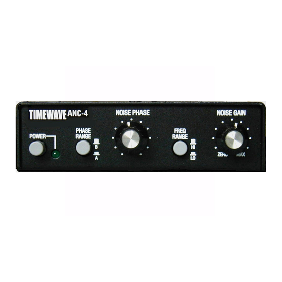
Page 10: Figure 1 Front Panel Controls
TIMEWAVE Figure 1 Front Panel Controls Figure 2 Rear Panel Controls... -
Page 11: Figure 3 Connection Diagram
+12VDC OUTSIDE NOISE FROM MAIN RADIO ANTENNA POWER ANTENNA ANTENNA SUPPLY INPUT Figure 3 Connection Diagram... -
Page 12: Connections
The RADIO (J2) connector is also a UHF (SO-239) type for use with coaxial rf cables, such as RG-8 or RG-58. This connector provides the VEHICULAR output from the antenna to the receiver. When the ANC-4 power is off, OPERATION the MAIN ANT is bypassed directly to the RADIO connector. -
Page 13: Controls & Indicators
This section explains the operation of the ANC-4 controls. See Figure 1 SECTION 4 for the location of Front Panel Controls. CONTROLS & INDICATORS The NOISE PHASE control adjusts the phase angle of the signal from the NOISE PHASE noise antenna to 180 degrees for maximum cancellation of the local noise. -
Page 14: Operation
SECTION 3, NOISE ANTENNA gives some hints for an external noise antenna and where it should be physically located. ACTIVE ANTENNA The ANC-4 can be used as an active antenna. The NOISE GAIN control can then be used to provide amplification of the signals received by the antenna. -
Page 15: General Operating Hints
NOISE GAIN control. You will likely find that the ANC-4 will make operation of a DSP noise reducer, such as the Timewave DSP-599zx., much more effective because the ANC-4 will eliminate noise before it gets into the receiver and affects the receiver AGC circuits. -
Page 16: Technical Information
SECTION 6 TECHNICAL INFORMATION Operating Frequency Range 500 kHz to 80 MHz SPECIFICATIONS (usable down to 100 kHz) Signal Loss, Main Ant. to Radio 6 dB Rf Input Level, Main Antenna 3 Vrms maximum Maximum Transmit Rf Power 250 W PEP or Average Through Unit Time to Switch to Bypass When 7 mSec, typical... -
Page 17: Troubleshooting
(is it a "buzz" or a "crackle", etc.?) (4) Disconnect the main antenna from the ANC-4. (5) Turn the NOISE GAIN control CW until it is somewhere in its mid-range and observe the S meter reading. Is it as high as the reading obtained in step 3? Is the character of the noise the same as that heard in step 3? If the answer to both questions is "YES", you... - Page 18 The noise antenna is then fed to the ANC-4 NOISE ANTENNA jack (rear of the unit) with shielded wire. Repeating the above tests will let you determine if you will be able to null the main antenna noise or not.
-
Page 19: General Theory Of Operation
Figure 6 is a block diagram of the ANC-4 showing the elements that are used to cancel SECTION 8 locally generated noise from the signal received by the station main antenna system. The station antenna picks up noise, both locally and remotely generated, as well as desired GENERAL signals and passes everything directly to the receiver. -
Page 20: Figure 4 Printed Circuit Board Parts Placement
Figure 4 Printed Circuit Board Parts Placement DESIRED SIGNAL LOCAL NOISE Strong Weaker Strong Main Weaker Noise J2 J3 RADIO ANC-4 Figure 5 Principle of Operation... -
Page 21: Figure 6 Block Diagram
Note: Relay shown in transmit/power off Figure 6 position Block Diagram For those who have access to the Internet, Timewave may be contacted at Email: techsupport@timewave.com service@timewave.com sales@timewave.com Timewave also has a Home Page on the World Wide Web http://www.timewave.com... -
Page 22: Figure 7 Schematic Diagram
JUPM 2 & 3 TOGETHER TO DISABLE TRAP St. Paul, MN 55117 USE JP3 FOR BCB FILTER Title 2.2u JUMP 1 & 2 TOGETHER FOR BC BAND FILTER ANC-4 Antenna Noise Canceller 100K JUMP 2 & 3 TOGETHER TO DISABLE FILTER Size Document Number R e v A.05300...
Need help?
Do you have a question about the ANC-4 and is the answer not in the manual?
Questions and answers
Hello how can I buy anc-4