Table of Contents
Advertisement
Quick Links
DCR-PC53E/PC55/PC55E
SERVICE MANUAL
Ver 1.0 2005. 01
Revision History
Revision History
How to use
How to use
Acrobat Reader
Acrobat Reader
N MECHANISM
Link
Link
SPECIFICATIONS
SPECIFICATIONS
SERVICE NOTE
SERVICE NOTE
DISASSEMBLY
DISASSEMBLY
• For ADJUSTMENTS (SECTION 6), refer to SERVICE MANUAL, ADJ (9-876-851-51).
• For INSTRUCTION MANUAL, refer to SERVICE MANUAL, LEVEL 1 (9-876-851-41). (EXCEPT J MODEL)
• For MECHANISM ADJUSTMENTS, refer to the "DV MECHANICAL ADJUSTMENT MANUAL IX
N MECHANISM " (EXCEPT J: 9-876-789-11) (J: 9-876-789-01).
• Reference number search on printed wiring boards is available.
• TO TAKE OUT A CASSETTE WHEN NOT EJECT (FORCE EJECT)
On the CR-049, FB-223, and VC-379 board
This service manual provides the information that is premised the circuit board replacement service and not intended repair
inside the CR-049, FB-223, and VC-379 board.
Therefore, schematic diagram, printed wiring board, waveforms, mounted parts location and electrical parts list of the CR-049,
FB-223, and VC-379 board are not shown.
The following pages are not shown.
Schematic diagram ............................. Pages 4-19 to 4-54
Printed wiring board ............................ Pages 4-65 to 4-72
Waveforms ........................................... Page 4-74
DCR-PC53E/PC55/PC55E
9-876-851-31
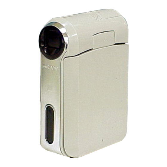
Photo : DCR-PC55
BLOCK DIAGRAMS
BLOCK DIAGRAMS
FRAME SCHEMATIC DIAGRAMS
FRAME SCHEMATIC DIAGRAMS
SCHEMATIC DIAGRAMS
SCHEMATIC DIAGRAMS
Mounted parts location ....................... Pages 4-76 to 4-77
Electrical parts list .............................. Pages 5-14 to 5-22
DIGITAL VIDEO CAMERA RECORDER
Sony EMCS Co.
RMT-831
LEVEL
DCR-PC53E
AEP Model
North European Model
DCR-PC55
Canadian Model
Korea Model
Tourist Model
Japanese Model
DCR-PC55E
AEP Model
Hong Kong Model
Australian Model
Chinese Model
North European Model
Tourist Model
PRINTED WIRING BOARDS
PRINTED WIRING BOARDS
REPAIR PARTS LIST
REPAIR PARTS LIST
Published by DI Technical Support Section
2
UK Model
US Model
E Model
UK Model
E Model
2005A1600-1
©2005.01
Advertisement
Table of Contents

Related Manuals for Sony DCR-PC53E


Summary of Contents for Sony DCR-PC53E
- Page 1 Mounted parts location ....... Pages 4-76 to 4-77 Printed wiring board ......Pages 4-65 to 4-72 Electrical parts list ......Pages 5-14 to 5-22 Waveforms ........... Page 4-74 DIGITAL VIDEO CAMERA RECORDER 2005A1600-1 DCR-PC53E/PC55/PC55E ©2005.01 Sony EMCS Co. 9-876-851-31 Published by DI Technical Support Section...
- Page 2 ENGLISH JAPANESE ENGLISH JAPANESE SPECIFICATIONS DCR-PC53E/PC55/PC55E — 2 —...
- Page 3 ENGLISH JAPANESE ENGLISH JAPANESE DCR-PC53E/PC55/PC55E — 3 —...
- Page 4 MARK 0 ON THE SCHEMATIC DIAGRAMS AND IN THE PARTS CRITIQUES POUR LA SÉCURITÉ DE FONCTIONNEMENT. NE LIST ARE CRITICAL TO SAFE OPERATION. REPLACE THESE REMPLACER CES COMPOSANTS QUE PAR DES PIÈSES SONY COMPONENTS WITH SONY PARTS WHOSE PART NUMBERS DONT LES NUMÉROS SONT DONNÉS DANS CE MANUEL OU APPEAR AS SHOWN IN THIS MANUAL OR IN SUPPLEMENTS DANS LES SUPPÉMENTS PUBLIÉS PAR SONY.
- Page 5 ENGLISH JAPANESE ENGLISH JAPANESE DCR-PC53E/PC55/PC55E — 5 —...
-
Page 6: Table Of Contents
• CONTROL SWITCH BLOCK (PS11300) (FUNCTION KEY) SCHEMATIC DIAGRAMS ·························· 4-15 • FP-228/FP-031/FP-032 FLEXIBLE SCHEMATIC DIAGRAMS ·························· 4-17 Schematic diagram of the CR-049, FB-223, FP-042 and VC-379 board are not shown. Pages from 4-19 to 4-54 are not shown. DCR-PC53E/PC55/PC55E — 6 —... -
Page 7: Note For Repair
When installing a connector, don't press down at wire of connector. Be in danger of the snapping of a wire. Cut and remove the part of gilt which comes off at the point. (Take care that there are some pieces of gilt left inside) DCR-PC53E/PC55/PC55E... -
Page 8: Power Supply During Repairs
Disconnect CN1002 (29P, 0.3mm) of VC-379 board. Supply +4.5V from the DC power supply to the loading motor and unload with pressing the cassette compartment. CN1002 Loading motor DC power supply (+4.5Vdc) VC-379 board Disconnect the flexible board from CN1002 of VC-379 board. DCR-PC53E/PC55/PC55E... -
Page 9: Self-Diagnosis Function
E : Corrected by service E.g. engineer 31 ..Reload the tape. 32 ..Turn on power again. Note: The self-diagnosis display data will be kept even if the lithium battery (BT8001 of FB-223 board) is removed. DCR-PC53E/PC55/PC55E... -
Page 10: Self-Diagnosis Code Table
Inspect pitch angular velocity sensor (SE8002 of FB-223 board) pitch angular velocity sensor output stopped.) peripheral circuits. Steadyshot function does not work well. (With Inspect yaw angular velocity sensor (SE8001 of FB-223 board) yaw angular velocity sensor output stopped.) peripheral circuits. DCR-PC53E/PC55/PC55E... - Page 11 SECTION 1 ENGLISH JAPANESE ENGLISH JAPANESE SERVICE NOTE DCR-PC53E/PC55/PC55E...
- Page 12 ENGLISH JAPANESE ENGLISH JAPANESE DCR-PC53E/PC55/PC55E...
- Page 13 ENGLISH JAPANESE ENGLISH JAPANESE ✂ ✂ DCR-PC53E/PC55/PC55E...
- Page 14 ENGLISH JAPANESE ENGLISH JAPANESE DCR-PC53E/PC55/PC55E 1-8E...
- Page 15 5 Control switch block (13P) 2 Screw (M1.7x4) damage the flexible board. (Silver)(White)(Black)(Red) 6 FP-050 flexible board (6P) 7 Gyro cushion 3 Remove the faont panel assembly in the direction of the arrow a. 4 Motor unit (8P) HELP 01 DCR-PC53E/PC55/PC55E...
- Page 16 2 Remove the AS tape. 2 Two claws 3 Remove the two cushions (R). 3 Hinge cover (C) 4 Three screws (M1.7x2.5) silver 4 Hinge cover (M) 5 Remove the LCD assembly 5 LCD hinge assembly in the direction of the arrow. DCR-PC53E/PC55/PC55E...
- Page 17 4 Three screws (M1.7x2.5) silver 4 FP-052 flexible board 5 CR-049 board Tapping screw Silver White 5 Remove the MS dust protection sheet. M1.4x4 6 FP-044 flexible board (80P) 6 Remove the MS tape. 3-348-998-61 7 Remove the two jk sheets. Black DCR-PC53E/PC55/PC55E...
- Page 18 Lens side (Silver) (White) Lens side (Black) (Red) (Silver) (White) (Black) (Red) Lens side [SERVICE POSITION TO CHECK THE VTR SECTION] Connection to Check the VTR Section (page 2-9) (Silver) (White) (Black) (Red) (Silver) (White) (Black) (Red) FP-050 flexible board DCR-PC53E/PC55/PC55E...
- Page 19 FP-050 flexible FP-044 flexible CN1003 board (6P) board (80P) CN1008 CN8004 FP-042 flexible CN1013 board (37P) VC-379 board FP-053 Caution Connect only when checking LCD block for ejection. Caution Connect this only when using the LCD and the touch panel. DCR-PC53E/PC55/PC55E...
-
Page 20: Circuit Boards Location
TIMING GENERATOR, A/D CONV. LENS DRIVE, MPEG MOVIE/DIGITAL STILL PROCESS, VC-379 HI/DIGITAL STILL CONTROL, 16M SDRAM, 64K EEPROM, DV/RF SIGNAL PROCESS, DV INTERFACE, REC/PB AMP, VIDEO, AUDIO I/O, ADC/DAC, DRUM/CAPSTAN/LOADING DRIVE, CAMERA/MECHA CONTROL, HI CONTROL, DC IN, CHARGE, DC/DC CONVERTER, CONNECTOR DCR-PC53E/PC55/PC55E 2-10... -
Page 21: Flexible Boards Location
2. DISASSEMBLY 2. DISASSEMBLY 2-4. FLEXIBLE BOARDS LOCATION The flexible boards contained in the mechanism deck and lens block are not shown. FP-054 FP-044 FP-049 FP-053 FP-042 CONTROL SWITCH BLOCK (PS11300) MOTOR UNIT DCR-PC53E/PC55/PC55E 2-11E... - Page 22 FB-223 M1.7x2.5 3-057-082-01 Gyro cushion HELP 02 Lens FP-052 flexible Lens device board VC-379 VC-379 Lens flexible sheet MS tape Fuse replacement caution label HELP 03 LCD hinge assembly Easy tally Interception sheet (upper) Projection Interception sheet (lower) DCR-PC53E/PC55/PC55E HELP...
- Page 23 HELP 05 FP-049 flexible board 8 Wrap around three times. Adhesive surface FP-053 flexible board assembly Control switch block 9 Attach the adhesive surface. FP-222 flexible board FP-053 flexible board HELP 06 MS dust protection sheet MS tape DCR-PC53E/PC55/PC55E HELP...
-
Page 24: Block Diagrams
OVERALL BLOCK DIAGRAM (1/4) POWER BLOCK DIAGRAM (1/2) OVERALL BLOCK DIAGRAM (2/4) POWER BLOCK DIAGRAM (2/2) OVERALL BLOCK DIAGRAM (2/4) POWER BLOCK DIAGRAM (2/2) OVERALL BLOCK DIAGRAM (3/4) OVERALL BLOCK DIAGRAM (3/4) OVERALL BLOCK DIAGRAM (4/4) OVERALL BLOCK DIAGRAM (4/4) DCR-PC53E/PC55/PC55E... - Page 25 (PAGE 3-3) USB D+,D- USB D+,D- STATION 16Mbit (5/15) SDRAM CR-049 BOARD(1/7) FP-044 (FLEXIBLE)(1/7) CN1010 CN8102 MEMORY STICK MS BS,DIO,SCLK MS BS,DIO,SCLK CONNECTOR XMS LED ON LED DRIVE D001 Q5101 (MS ACCESS) FP-052 AUDIO SIGNAL VIDEO SIGNAL (FLEXIBLE) VIDEO/AUDIO SIGNAL DCR-PC53E/PC55/PC55E...
- Page 26 (PAGE 3-2) MIC R CN1009 FP-044 (FLEXIBLE)(4/7) CN8504 FPC-MIC CR-049 BOARD(4/7) (FLEXIBLE) MIC901 CN8505 (1/2) FP-054 (FLEXIBLE) IC4501 MIC L (1/2) MIC R MIC AMP CN8507 INTELLIGENT SHOE MIC FL ACCESSORY AUDIO SIGNAL SHOE MIC FR VIDEO SIGNAL SHOE (1/2) DCR-PC53E/PC55/PC55E...
- Page 27 CHIME SDA,CHIME SCK,CHIME VDD TAPE TOP SENSOR XCC DOWN LED9001 MODE SW A,B,C TAPE LED S9002 REC PROOF REC PROOF MIC9002 CHIME SDA,CHIME SCK,CHIME VDD 4PIN CONNECTOR XCC DOWN S9001 C. C. DOWN MODE SW A,B,C MODE DIGITAL VIDEO/AUDIO SIGNAL SWITCH S9003 DCR-PC53E/PC55/PC55E...
- Page 28 MULTI OVERALL BL CONT CONNECTOR BLOCK DIAGRAM(2/4) S8501 HANDYCAM (PAGE 3-3) STATION PHOTO SW 39-42 KEY AD4 PHOTO FREEZE CN8502 ( 5/5 ) BATT UNREG PHOTO REC HANDYCAM VTR UNREG STATION J8601 DC IN Q2008,2009 SHOE UNREG CN1009 CN8504 DCR-PC53E/PC55/PC55E...
- Page 29 L8001 VREG5 POWER BLOCK IC8002 A 2.8V BL -15.5V EP 8.5V 8.5V REG DIAGRAM D 2.8V (2/2) PITCH/YAW (PAGE 3-12) D 2.8V SEMSOR AMP SE8001,8002 BL CONT PITCH/YAW CAM DD ON CN1013 CAM DD ON SEMSOR FP-042 (FLEXIBLE) DCR-PC53E/PC55/PC55E 3-10...
- Page 30 (2/15) CAM -7.5V IC4101 IC3802 IC3801 (1/15) CAM -7.5V IMAGER IC6001 VG IC3001 CN5001 2.8V REG FOCUS/ZOOM/ INTERFACE IRIS/LENS BARRIER S/H,AGC DRIVE A/D CONV. FP-223 (FLEXIBLE) CN1001 ZOOM SENSOR 2.8V MR A2.8V FOCUS LENS ASSY CN101 SENSOR DCR-PC53E/PC55/PC55E 3-11 3-12E...
- Page 31 FLEXIBLE ZOOM_VR_AD ZOOM_VR_AD CN8004 XRESET BOARD XRESET FP-051 XEJECT_SW XEJECT_SW N.C. FLEXIBLE BOARD N.C. FUNCTION SW,LED N.C. N.C. CN001 BT8001 CONTROL SWITCH BLOCK N.C. BATTERY TERMINAL LITHIUM BATTERY (PS11300) (SECONDARY) N.C. FP-050 FLEXIBLE BOARD EJECT SW DCR-PC53E/PC55/PC55E FRAME SCHEMATIC DIAGRAM...
-
Page 32: Schematic Diagrams
MS CONNECTOR) (PS11300) MS CONNECTOR) FP-053 FLEXIBLE BOARD FP-228/FP-031/FP-032 FLEXIBLE BOARD FP-228/FP-031/FP-032 FLEXIBLE BOARD FP-053 FLEXIBLE BOARD (VC-PD RELAY) (VC-PD RELAY) FP-054 FLEXIBLE BOARD FP-054 FLEXIBLE BOARD COMMON NOTE FOR SCHEMATIC DIAGRAMS WAVEFORMS COMMON NOTE FOR SCHEMATIC DIAGRAMS WAVEFORMS DCR-PC53E/PC55/PC55E... - Page 33 Les composants identifiés par mark 0 or dotted line with mark une marque 0 sont critiques 0 are critical for safety. pour la sécurité. Replace only with part number Ne les remplacer que par une specified. pièce portant le numéro spécifié. DCR-PC53E/PC55/PC55E...
- Page 34 ENGLISH JAPANESE 4-2. SCHEMATIC DIAGRAMS ENGLISH JAPANESE 4-2. SCHEMATIC DIGARAMS (JAPANESE) PTB-450: PTB-450 J-6082-200-A J-6020-250-A PTB-1450 PTB-1450: J-6082-559-A J-6082-557-A 0.4m (PTB-1450) 1.0m (PTB-450) FP-048 FP-048 DCR-PC53E/PC55/PC55E...
- Page 35 SHOE_CONT AU_2.8V AU_2.8V D_2.8V D2.8V ACV_UNREG FP-044 FLEXIBLE BOARD is replaced ACV_UNREG ACV_UNREG ACV_UNREG ACV_UNREG as a block. ACV_UNREG ACV_UNREG ACV_UNREG ACV_UNREG So that this PRINTED WIRING BOARD ACV_UNREG ACV_UNREG ACV_UNREG ACV_UNREG is omitted. ACV_UNREG ACV_UNREG ACV_UNREG N.C. DCR-PC53E/PC55/PC55E FP-044...
- Page 36 LND396 LND411 R10.5 CCD_OUT CCD_GND IC3901 IC3901 LND397 LND412 C3902 ICX440HKZ-13 (DCR-PC55) CCD_GND CCD_GND C3901 0.01u L3901 (Note1, 2) ICX441HKZ-13 (DCR-PC53E/PC55E) LND398 LND413 100uH CCD_GND CCD_GND LND399 LND414 R3901 R3902 CCD_GND 3300 (DCR-PC55) LND400 LND415 (DCR-PC53E/PC55E) CCD_GND CCD_GND IC3901 LND401...
- Page 37 VD_SO So that this PRINTED WIRING BOARD is omitted. LND624 LND651 LND625 LND652 LND626 LND653 XEASY_LED XEASY_LED LND627 LND654 BATT_INFO BATT_INFO FP-053 FLEXIBLE BOARD is replaced as a block. So that this PRINTED WIRING BOARD is omitted. DCR-PC53E/PC55/PC55E FP-051/FP-052/FP-053/FP-054 4-10...
- Page 38 LENS BLOCK is replaced as a block. So that this PRINTED WIRING BOARD and SCHEMATIC DIAGRAM are omitted. FP-223 FLEXIBLE BOARD is replaced as a block. So that this PRINTED WIRING BOARD is omitted. DCR-PC53E/PC55/PC55E FP-222/FP-223/LENS SHUTTER FPC/MIC FPC 4-11 4-12...
- Page 39 R7539 Q7501 Q7516 XP4211-TXE Q7514 UN9113J-(K8).SO R7534 SWITCH UP04601008S0 SWITCH BL CONT Q7513 R7533 C7512 C7532 R7507 C7531 R7548 R7546 2SB1462J-QR(K8).SO R7540 R7537 R7536 3300 3300 4.7u ± BL CONT 0.5% R7501 R7503 R7505 LND751 CH_GND DCR-PC53E/PC55/PC55E PD-239 4-13 4-14...
- Page 40 EVER_3.0V CAMERA XPOWER_SW XMODE_SW D8302 MEMORY XRESET R8302 REG_GND D8303 D8304 SML-512WWT86 MODE POWER POWER S8302 RESET LN8301 CHASSIS_GND CONTROL SWITCH BLOCK (PS11300) is replaced as a block. So that this PRINTED WIRING BOARD is omitted. DCR-PC53E/PC55/PC55E PS11300 4-15 4-16...
- Page 41 PROOF FLEXIBLE BOARD 4 PIN CONNECTOR MIC9002 H9002 FP-031 HW-105A-CDE-T (T REEL SENSOR) FLEXIBLE BOARD Schematic diagram of the CR-049, FB-223, FP-042 and VC-379 board are not shown. Pages from 4-19 to 4-54 are not shown. DCR-PC53E/PC55/PC55E FP-228/FP-031/FP-032 4-17 4-18...
-
Page 42: Printed Wiring Boards
TIMING GENERATOR, A/D CONV. LENS DRIVE, MPEG MOVIE/DIGITAL STILL PROCESS, VC-379 HI/DIGITAL STILL CONTROL, 16M SDRAM, 64K EEPROM, DV/RF SIGNAL PROCESS, DV INTERFACE, REC/PB AMP, VIDEO, AUDIO I/O, ADC/DAC, DRUM/CAPSTAN/LOADING DRIVE, CAMERA/MECHA CONTROL, HI CONTROL, DC IN, CHARGE, DC/DC CONVERTER, CONNECTOR DCR-PC53E/PC55/PC55E... - Page 43 CR-049 – 4-76 2 to 5 FP-048 4-73 – – FP-050 – – – FP-051 – – – FP-052 – – – FP-222 – – – PD-239 4-73 – – VC-379 4-74 4-76,77 2 to 7 DCR-PC53E/PC55/PC55E 4-55...
- Page 44 • Refer to page 4-55 for common note for printed wiring board. FP-048 BOARD(SIDE B) FP-048 BOARD(SIDE A) IC3901 R3902 L3901 IC3901 is included in this R3901 FLEXIBLE BLOCK ASS'Y, CCD. (PC55:A-1087-297-A, PC53E/PC55E:A-1087-298-A) C3903 1-864-922- 1-864-922- FP-050 BOARD EJECT LND302 LND303 LND304 LND305 LND306 1-864-924- DCR-PC53E/PC55/PC55E FP-048/FP-050 4-57 4-58...
- Page 45 • Refer to page 4-55 for common note for printed wiring board. FP-051 BOARD FP-052 BOARD BACK LIGHT LND811 START/STOP ON/OFF BACK LIGHT BATT INFO EASY R403 R401 S405 S404 S402 1-864-925- CN8102 MEMORY STICK DUO CONNECTOR 1-864-926- D001 DCR-PC53E/PC55/PC55E FP-051/FP-052 4-59 4-60...
- Page 46 SENSOR FP-031 Dilect Solder FLEXIBLE BOARD Dilect Solder FP-222 BOARD 1-864-871- Q9001 TAPE END SENSOR LND231 S221 LND229 LND230 LND227 LND228 LND225 LND226 LND223 LND224 FP-222 >PI< (PANEL REVERS) LND221 LND222 1-864-929- IC221 (PANEL O/C SENSOR) DCR-PC53E/PC55/PC55E FP-222/FP-228/FP-031/FP-032 4-61 4-62...
- Page 47 D7506 R7539 Q7515 R7537 R7505 D7503 R7535 R7550 Q7501 LND751 CN7504 CN7503 CN7505 1-864-917- Printed wiring board of the CR-049, FB-223 and VC- 379 board are not shown. Pages from 4-65 to 4-72 are not shown. DCR-PC53E/PC55/PC55E PD-239 4-63 4-64...
- Page 48 3.0 Vp-p 310 mVp-p IC7501 wa IC7501 rs 3.2 Vp-p 2.8 Vp-p IC7501 wf IC7501 rd 4.8 Vp-p 2.8 Vp-p IC7501 ek 330 mVp-p Waveforms of the VC-379 board is not shown. Page from 4-74 is not shown. DCR-PC53E/PC55/PC55E FP-048/PD-239 4-73...
-
Page 49: Mounted Parts Location
R7549 B-4 IC7501 B-3 R7550 C-4 R7551 B-3 L7501 R7552 B-3 L7502 R7553 B-3 L7503 R7554 B-2 L7504 R7555 B-2 Mounted parts location of the VC-379 board is not shown. Pages from 4-76 to 4-77 are not shown. DCR-PC53E/PC55/PC55E PD-239 4-75E... -
Page 50: Repair Parts List
CR-049 BOARD FP-048 FLEXIBLE BOARD FP-052 FLEXIBLE BOARD CR-049 BOARD FP-050 FLEXIBLE BOARD FP-222 FLEXIBLE BOARD FB-223 BOARD FP-050 FLEXIBLE BOARD FP-222 FLEXIBLE BOARD FB-223 BOARD FP-051 FLEXIBLE BOARD PD-239 BOARD VC-379 BOARD FP-051 FLEXIBLE BOARD PD-239 BOARD VC-379 BOARD DCR-PC53E/PC55/PC55E... - Page 51 Ne les remplacer que par une pièce portant F: nonflammable le numéro spécifié. • SEMICONDUCTORS In each case, u: µ, for example: (JAPANESE) uA...: µA... , uPA... , µPA... , uPB... , µPB... , uPC... , µPC... , uPD..., µPD... (JAPANESE) • Abbreviation : Japanese model DCR-PC53E/PC55/PC55E...
-
Page 52: Exploded Views
X-2048-831-1 CABINET (R) ASSY (BLACK) (RED) 3-080-204-21 SCREW, TAPPING, P2 2-581-814-01 CUSHION, PANEL X-2048-816-1 CABINET ASSY, TOP 2-581-815-01 SHEET, FOOT X-2048-806-1 COVER ASSY, SHOE (SILVER) 3-052-196-01 TAPE AS X-2048-807-1 COVER ASSY, SHOE (BLACK) 2-594-083-01 CUSHION (R) MIC901 1-542-612-11 MICROPHONE UNIT DCR-PC53E/PC55/PC55E... - Page 53 Danger of explosion if battery is incorrectly replaced. Replace only with part number specified. Replace only with the same or equivalent type. Les composants identifiés par une marque 0 sont critiques pour la sécurité. Ne les remplacer que par une pièce portant le numéro spécifié. DCR-PC53E/PC55/PC55E...
- Page 54 The components identified by mark 0 or dotted line with mark 0 are critical for safety. Replace only with part number specified. Les composants identifiés par une marque 0 sont critiques pour la sécurité. Ne les remplacer que par une pièce portant le numéro spécifié. DCR-PC53E/PC55/PC55E...
-
Page 55: Lcd Section
2-593-915-01 TAPE (5X15), BLACK 2-581-833-11 CABINET (C), P (BLACK) 2-593-916-01 SHEET (LOWER), INTERCEPTION (RED) (WHITE) 2-581-833-21 CABINET (C), P (WHITE) LCD901 A-1083-764-A TP BLOCK ASSY 30SHGU 2-581-833-31 CABINET (C), P (RED) LED901 1-478-926-11 BLOCK, LIGHT GUIDE PLATE (3.0) SP901 1-825-997-11 BUZZER, PIEZOELECTRIC DCR-PC53E/PC55/PC55E... -
Page 56: Overall Mechanism Deck Section
3-079-366-11 RELEASE, REEL LOCK A-1080-997-A MD(N100)SUB ASSY_A 3-703-816-08 SCREW (M1.4X1.4), SPECIAL HEAD 3-703-816-13 SCREW (M1.4X2.0), SPECIAL HEAD X-2024-450-1 COMPARTMENT ASSY, CASSETTE 3-315-414-31 WASHER 2-342-926-01 SPRING (ARM S), TENSION COIL M9001 A-1087-172-A DRUM ASSY (DEH-33A-R) (SERVICE) 2-546-417-01 SCREW (M1.4) 2-342-933-01 PLATE, TOP DCR-PC53E/PC55/PC55E... - Page 57 3-703-816-13 SCREW (M1.4X2.0), SPECIAL HEAD 2-342-705-01 GEAR (T), GL X-2024-466-1 COASTER (T) ASSY 2-342-902-01 SPRING, TENSION REGULATOR X-2024-469-1 ARM (T) ASSY, GL X-2024-474-1 TABLE ASSY,T REEL 2-342-716-01 SPRING (T), TORSION COIL X-2024-476-1 ARM ASSY,PINCH 3-703-816-08 SCREW (M1.4X1.4), SPECIAL HEAD (for adjustment) DCR-PC53E/PC55/PC55E...
- Page 58 8-719-067-74 ELEMENT, HOLE HW-105A-CDE-T (T REEL) X-2024-461-1 GEAR ASSY, MODE M9002 X-2024-464-1 MOTOR ASSY (LORDING) 2-342-615-01 GEAR,NO.2 MIC9002 1-818-576-11 PIN, CONNECTOR (WITH DETECTION SWITCH) 2-342-691-01 GEAR,NO.1 Q9001 6-550-672-01 TRANSISTOR PT4850FJE00F (TAPE END) 2-342-688-01 MOTOR HOLDER Q9002 6-550-672-01 TRANSISTOR PT4850FJE00F (TAPE TOP) DCR-PC53E/PC55/PC55E...
-
Page 59: Checking Supplied Accessories
0 or dotted line with mark une marque 0 sont critiques (PC53E:AEP/PC55E:AEP) 0 are critical for safety. pour la sécurité. 2-548-726-71 MANUAL, INSTRUCTION (GERMAN) Replace only with part number Ne les remplacer que par une (PC53E:AEP/PC55E:AEP) specified. pièce portant le numéro spécifié. DCR-PC53E/PC55/PC55E 5-10... - Page 60 5. REPAIR PARTS LIST 5. REPAIR PARTS LIST • J MODEL DCR-PC53E/PC55/PC55E 5-11...
-
Page 61: Electrical Parts List
1-771-138-82 SWITCH, KEY BOARD (2ND START/STOP) CN7504 1-785-905-11 CONNECTOR, FFC/FPC (ZIF) 24P ************************************************************ CN7505 1-794-322-11 CONNECTOR, FFC/FPC (ZIF) 6P CN7506 1-794-410-11 CONNECTOR, FPC (ZIF) 27P Be sure to read “Precautions upon replacing CCD imager” on page 4-3 when changing the CCD imager. DCR-PC53E/PC55/PC55E 5-12... - Page 62 1-218-959-11 RES-CHIP 3.3K 1/16W R7534 1-218-953-11 RES-CHIP 1/16W R7537 1-218-969-11 RES-CHIP 1/16W R7538 1-218-963-11 RES-CHIP 6.8K 1/16W R7539 1-218-950-11 RES-CHIP 1/16W R7540 1-218-969-11 RES-CHIP 1/16W R7541 1-208-643-11 METAL CHIP 0.5% 1/16W R7545 1-218-990-11 SHORT CHIP R7546 1-216-864-11 SHORT CHIP DCR-PC53E/PC55/PC55E 5-13E...
- Page 63 ENGLISH JAPANESE ENGLISH JAPANESE [Description of main button functions on toolbar of the Adobe Acrobat Reader Ver5.0 (for Windows)] Toolbar Printing a text Reversing the screens displayed once • To reverse the previous screens (operation) one by one, click 1. Click the Print button 2.
- Page 64 ENGLISH JAPANESE ENGLISH JAPANESE...
-
Page 65: Revision History
Reverse 987685131.pdf Revision History S.M. Rev. Ver. Date History Contents issued 2005.01 Official Release — — DCR-PC53E/PC55/PC55E...
Need help?
Do you have a question about the DCR-PC53E and is the answer not in the manual?
Questions and answers