Table of Contents
Advertisement
Quick Links
See also:
User Manual
Advertisement
Table of Contents

Related Manuals for HiTi Digital Photo Printer 640PS


Summary of Contents for HiTi Digital Photo Printer 640PS
-
Page 1: Service Guide
Confidential 64xPS/ID Service Guide Version: 1.1 The Service Guide was written mainly for engineers. Please Do Not rep roduce and dup licate. - Page 2 Confidential Chapter 1: Overview Chapter 2: Theory of Operation, Mechanism, Firmware Chapter 3: Disassembly, Index of Parts, Tools required Chapter 4: Adjustments Chapter 5: Contact Information...
-
Page 3: Chapter 1: Overview
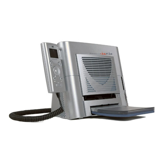
640PS 641PS HiTi Photo Printer 640PS and 641PS are p opular p rinters able to p rint in high-sp eed & high-quality . HiTi p hoto p rinters are sty lish and compact. HiTi p rinters can p rint 6x4”... -
Page 4: Specifications
Confidential YM CO 4 p asses (Yellow, Magenta, Cy an, and Over-coating) Over coating ensures that HiTi’s p rintouts can be kep t a longer time than inkjet p rinter’s p rintouts. High Quality Resolution 640PS and 641PS: 403 x403 dp i Convenience All HiTi Photo Printer ship with “Photo Desiree”, a p hoto editing p rogram... -
Page 5: Chapter 2: Theory Of Operation
Confidential Windows 98/ M E/ 2000/ XP Operating System Linux & Mac OS 10.2 and abov e Minimum S ystem Win 98/M E: 64M B RAM , Pentium PC Requirement Win 2000/ XP: 128M B RAM, Pentium PC Certification UL, TUV-GS, FCC, CE, BSM I, CCC, C-Tick, VCCI Pap er Cassette, USB cable, CD-ROM (with p rinter drivers, bundle software and electronic manual), AC Accessories Included... -
Page 6: Thermal Print Head (Tph)
Confidential Hardware Thermal Print Head (TPH) Thermal Print Head (TPH) is the key comp onent for D2T2 printer, like the inkjet printing head for inkjet printer. Driver IC He ating Ele ment... -
Page 7: Main Board & Asic
The ASIC is an IC (Integrated Chip ) located on the Main Board. The ASIC was designed by the HiTi R&D dep artment and features an 8032 MCU. The ASIC drives the USB controller, controls the embedded SDRAM , MCU I/F, USB I/F, memory I/F, and GIO interface. -
Page 8: Power Board
Confidential Power Board It contains a universal AC inp ut, DC +18V/7V outp ut and a USB interface. The VR (variable resistance) on the p ower board is used to adjust the voltage of the THP. This controls the color density of the printout. The illustration below shows the image of a 640PS power board. -
Page 9: Tph Board
Confidential TPH Board The TPH Board connects the cables (Ribbon LED cable, TPH Cable, Cassette Sensor Cable, Fan Cable). The TPH board connects then to the motherboard. TPH Board... - Page 10 Confidential Card Board (640PS and 641PS) 640PS : There are 2 memory card sockets on the card board. One is for Comp act Flash and the other is for Smart M edia/ M ulti-M edia-Card/ Secure Digital C ard/Memory Stick. 641PS : The 641 PS card board features an enh anced U SB Connector.
- Page 11 Confidential The illustration below shows the 641 PS card boa rd 4 in 1 memory card CompactFlash USB DataLink socket socket Socket...
- Page 12 Confidential Controller Board (640PS and 641PS) This controller board uses an 80-series CPU with 4KB on-chip FLASH EPROM for the central control – this would include an initial setting of the LCD driver IC, the LED backlight control, the button-pushed sensing and commun ication with the main board. The serial EPROM stores the setting data of the LCD that was received at the calibration process.
-
Page 13: Cam Motor
Confidential Motor Cam motor The Cam motor is a bipolar motor which d rives the CAM to control the Platen roller’s & Pinch roller’s position. Capstan motor The Capstan motor is a bip olar motor which drives the Capstan roller to control the movement of the p ap er. - Page 14 Confidential LED & Sensor Status/ Error LED The Status/Error LED indicates the status of the p rinter. It also communicates any error messages. For examp le: The steadily shining Green LED indicates the ready stage of the p rinter. The blinkin g Green LED indicates that the p rinter is busy. The blinking Oran ge LED indicates that an error has hap pened.
-
Page 15: Cam Sensor
Confidential Cam Sensor Dep ending on the p rinter’s status, the p ositions of the p laten roller and the pinch roller stay different. The Cam controls the movement of the p laten roller between these positions, and the Cam sensor detects & feeds the p osition’s information back to the firmware. - Page 16 Confidential Leading Edge (LE) Sensor and Jam Sensor The p urp ose of both sensors is to detect the status of pap er. The sensor will be on when it detects the loading of pap er. The LE Sensor will b e off if it does not detect pap er loading. Le ading Edge sensor Jam se nsor...
-
Page 17: Ribbon Cassette Sensor
Confidential Ribbon Cassette (Door) Sensor It is used to detect the status of the ribbon cassette and the ribbon door. The ribbon cassette sensor will be on if the ribbon cassette typ e is correct; the Ribbon Cassette Sensor will b e off if the ribbon cassette typ e is wrong. Ribbon Cassette sensor... -
Page 18: Ribbon Led/ Ribbon Sensor
Confidential Ribbon LED/ Ribbon Sensor The Ribbon LED and Ribbon Sensor is used to detect the ribbon status, it enables the printer to detect the correct ribbon color. At the y ellow or overcoat lay er, the ribbon sensor detects a HIGH value. In the magenta and cy an lay er, the ribbon sensor detects a LOW value. - Page 19 Confidential The Fan reduces the temp erature of the TPH (Thermal Print Head). The fan only starts to op erate as soon as the temp erature reaches a certain degree.
- Page 20 Confidential Mechanism Basic Anatomy A: Eject button B: Case back C: Main board D: Bracket and p ower-board E: TPH board F: Chassis G: Case front H: Ribbon door I: Paper door J: Paper cassette K: Card board L: Controller M: Controller hold er Transmission The Auto Document Feed (ADF)/ Ribbon search device...
- Page 21 Confidential 1. When the ADF M otor rotates the pap er lifter gearin g chain, the Pap er Lifter device starts lifting the elev ator p late in the p ap er cassette up . The p ap er which lies at the top p osi t ion will then be in contact with the pap er take up roller.
-
Page 22: Cam Position
Confidential Cam position: When the Cam M otor rotates, it will continue to operate Gear 1, Gear 2, Gear 3, Gear 4, and Gear 5 in sequ ence. It will transfer p ower to another side of the Peel Bar after it receives p ower by Gear 5. -
Page 23: Firmware Update
As the firmware is stored in the IC of the main board, y ou need to use the easy to use BurnFW.exe app lication in order to update the p rinter’s firmware. Firmware up dates can easily be downloaded from the HiTi supp ort website: Go to www.hi-ti.com, then find the ‘Support’ section. - Page 24 Confidential Host job flow: After the p rinter is p owered on, the firmware will control the p rinter’s op eration. Printing Step Related Motor Related Sensor Check Ribbon Cassette type Ribbon Cassette Cam load to print position Loa d pa per Cap stan Ribbon registration (Y) Ribbon...
-
Page 25: Error Messages
Confidential Error messages: The firmware controlled Status LED shows the error status: Green Signal Light: Stable: Printer is ready for p rocessing job Blinking slowly: Printer is p rocessing job or initializin g after p ower on Blinking fast: Printer is writing firmware IMPORTANT: NEVER TURN THE PRINTER OFF WHILE ANY LIGHT IS BLINKING OR WHILE YOU CAN STILL HEAR OPERATIONAL SOUNDS FROM THE PRINTER... -
Page 26: Chapter 3: Disassembly
Confidential Chapter 3: Disassembly Safety Instructions for all HiTi products: Printers • Read these instructions carefully. Save these instructions for future reference. • Follow all warnin gs and instructions marked on the printer. • Unp lug the p rinter from the wall outlet before disassembly. - Page 27 Confidential Tools Tweezers Screwdriver – minus...
- Page 28 Confidential Screwdriver – plus IC Clamp...
-
Page 29: Wire Cutter
Confidential Wire Cutter... -
Page 30: Do Not Disassemble These Parts
Confidential Do not disassemble these Parts: HiTi strictly prohibits anyone to disassemble the TPH (Thermal Print Head) the Bracket-idle. Both parts need to be calibrated by a specific calibration device and cannot be repaired on site: Bracket-idle:... - Page 31 Confidential Disassembly Click to go to the Visual Disassembly Controller Controller cable Controller board Case Ribbon door Case front Bracket Eject button Case back Main board 640PS Main board 641PS Power board THP board Card board 640PS Card board 641PS Motor ADF motor Cam motor...
- Page 32 Confidential Vis ual Disassembly:...
-
Page 33: Adf Motor
Confidential ADF MOTOR Op en ribbon door Bend both sides of ribbon door back to remove it Unscrew 2 screws from case back... - Page 34 Confidential Sep arate case front and case b ack with chassis Unscrew 3 screws from chassis Unscrew 2 screws from ADF motor frame...
- Page 35 Confidential Unp lug connector from main board Take ADF motor out...
- Page 36 Confidential BRACKET Unscrew 4 screws from bracket Unp lug 5 connectors from p ower board Unscrew screw from bracket...
- Page 37 Confidential Sep arate case back and bracket with power board Unscrew 5 screws from p ower board Sep arate p ower board and bracket...
-
Page 38: Cam Motor
Confidential CAM MOTOR Unscrew 2 screws from case back Sep arate case front and case b ack with chassis. Unscrew 3 screws from chassis... - Page 39 Confidential Unscrew 3 screws from the card board Unscrew 2 screws from the cam motor...
- Page 40 Confidential Unp lug connector from main board Take cam motor out...
- Page 41 Confidential CAM S ENSOR Op en ribbon door Bend both sides of ribbon door back to remove it Unscrew 2 screws from case back...
- Page 42 Confidential Sep arate case front and case b ack from chassis Unscrew 3 screws from chassis Unscrew 2 screws from cam sensor...
- Page 43 Confidential Unp lug connector from main board Take cam sensor out...
-
Page 44: Capstan Motor
Confidential CAPSTAN MOTOR Op en ribbon door Bend both sides of ribbon door back to remove it Unscrew 2 screws from case back... - Page 45 Confidential Sep arate case front and case b ack with chassis Unscrew 3 chassis screws Unscrew 2 screws from cap stan motor...
- Page 46 Confidential Unp lug connector from main board Take capstan motor out...
- Page 47 Confidential CAPSTAN ROLLER Op en ribbon door. Bend both sides of ribbon door back to remove it Unscrew 2 screws from case back...
- Page 48 Confidential Sep arate case front and case b ack with chassis Unscrew 3 chassis screws Unscrew 3 screws from ADF motor frame...
- Page 49 Confidential Unscrew 2 screws from tray front Remove blu e ribbon hold er Take tray front out...
- Page 50 Confidential Release p inch sp ring. (Ap p ly caution when you p ull down the sp ring) App ly caution when y ou release the spring. Do not stretch the sp ring and do not p ull too hard.
- Page 51 Confidential Pull p inch roller (see Pin ch Roller section for more details)
- Page 52 Confidential Unscrew 3 card board screws Unscrew 3 screws holding the cap stan motor frame Unscrew 3 screws from cam motor frame...
- Page 53 Confidential Take p ulley out (from cap stan roller) Take e-rin g out (from cap stan roller)
- Page 54 Confidential Take p inch roller out...
- Page 55 Confidential CARD BOARD 641PS Op en ribbon door Bend both sides of ribbon door back to remove it Unscrew 2 screws from case back...
- Page 56 Confidential Sep arate case front and case b ack with chassis Unscrew 3 chassis screws Unscrew 3 card board screws...
- Page 57 Confidential Unp lug 3 connectors from card board Take out card board...
- Page 58 Confidential CARD BOARD CABLE Op en the ribbon door. Bend both sides of ribbon door back to remove it Unscrew 2 screws from case back...
- Page 59 Confidential Sep arate case front and case b ack with chassis Unscrew 3 screws from chassis Unp lug connector from card board...
- Page 60 Confidential Unp lug connector from main board Take card board cable out...
- Page 61 Confidential CARD BOARD Op en ribbon door Bend both sides of ribbon door back to remove it Unscrew 2 screws from case back...
- Page 62 Confidential Sep arate case front and case b ack with chassis Un-screw 3 chassis screws Unscrew 3 card board screws...
- Page 63 Confidential Unp lug 2 connectors from card board Take card board out...
-
Page 64: Case Back
Confidential CASE BACK Op en ribbon door Bend both sides of ribbon door backwards to remove it Unscrew 2 screws from case back... - Page 65 Confidential Sep arate case front and case b ack with chassis Unscrew 3 screws from chassis Take eject button out of case back...
- Page 66 Confidential Unscrew the ground wire screw and unp lug the 2 conn ectors from main bo ard. Separate case back and chassis Unscrew 4 screws from bracket...
- Page 67 Confidential Unp lug 3 connectors from p ower board. Unscrew the screws from bracket Take p ower inlet and switch out of case back...
- Page 68 Confidential Take case back out...
-
Page 69: Case Front
Confidential CASE FRONT Op en ribbon door Bend both sides of ribbon door back to remove it Unscrew 2 screws from case back... - Page 70 Confidential Sep arate case front from case back with chassis...
-
Page 71: Controller Board
Confidential CONTROLLER BOARD Unscrew 4 screws from controller case back Unp lug connector of controller cable fro m controller bo ard Unp lug 2 connectors from LCD from controller bo ard Take out controller IC... - Page 72 Confidential Take controller board out...
-
Page 73: Controller Cable
Confidential CONTROLLER CABLE Unscrew 4 screws from controller case back Unp lug connector of controller cable fro m controller bo ard... - Page 74 Confidential Take controller cab le out...
-
Page 75: Door Sensor
Confidential DOOR SENSOR Op en ribbon door. Bend both sides of ribbon door back to remove it Unp lug connector from TPH board Remove glu e on door sensor... - Page 76 Confidential Push ribs on both sides and take door sensor out Take door sensor out...
-
Page 77: Eject Button
Confidential EJECT BUTTON Op en ribbon door Bend both sides of ribbon door back to remove it Unscrew 2 screws from case back... - Page 78 Confidential Sep arate case front and case b ack with chassis. Unscrew 3 screws from chassis Take eject button out of case back...
- Page 79 Confidential...
- Page 80 Confidential Op en ribbon door Bend both sides of ribbon door back to remove it Unscrew 2 screws holding the fan Unp lug fan connector from TPH board...
- Page 81 Confidential Take fan out...
- Page 82 Confidential IC FLASH Op en ribbon door. Bend both sides of ribbon door back to remove it Unscrew 2 screws from case back...
- Page 83 Confidential Sep arate case front and case b ack with chassis Unscrew 3 screws from chassis Take IC flash out...
- Page 84 Confidential...
-
Page 85: Jam Sensor
Confidential JAM SENSOR Op en ribbon door. Bend both sides of ribbon door back to remove it Unscrew 2 screws from case back... - Page 86 Confidential Sep arate case front and case b ack with chassis Unscrew 3 screws from chassis Remove glu e on jam sensor...
- Page 87 Confidential Unp lug connector from main board Take jam sensor out...
- Page 88 Confidential LEADING EDGE SENSOR Op en ribbon door. Bend both sides of ribbon door back to remove it Unscrew 2 case back screws...
- Page 89 Confidential Sep arate case front and case b ack with chassis Unscrew 3 chassis screws Unscrew 3 screws from ADF motor frame...
- Page 90 Confidential Unscrew 2 tray front screws Remove blu e ribbon hold er. Take tray front out.
- Page 91 Confidential Unp lug connector from main board (shown: 640PS main board) Unscrew screw holding Leading Ed ge sensor (LE Sensor)
- Page 92 Confidential Take Leadin g Ed ge sensor out...
- Page 93 Confidential MAIN BOARD = Mother Board (640PS) Op en ribbon door Bend both sides of ribbon door back to remove it Unscrew 2 screws from case back...
- Page 94 Confidential Sep arate case front and case b ack with chassis Unscrew 3 screws from chassis Unp lug 2 connectors from main bo ard (shown: 640PS main board) Sep arate case back and ch assis...
- Page 95 Confidential Take IC flash out Unscrew 2 screws and unp lug other connectors from main board Take main board out (shown 640PS main bo ard)
- Page 96 Confidential MAIN BOARD = Mother Board (641PS) Op en ribbon door Bend both sides of ribbon door back to remove it Unscrew 2 screws from case back...
- Page 97 Confidential Sep arate case front and case back with chassis. Unscrew 3 chassis screws Unp lug 3 connectors from main bo ard (Shown: 641PS M ain Board) Sep arate case back and ch assis...
- Page 98 Confidential Take IC flash out Unscrew 2 screws and unp lug the other connectors from main board Please note: The blue square ind icates the location of conn ector for the data link cable (641PS). Take main board out (Shown: 641P S M ain Board)
-
Page 99: Pinch Roller
Confidential PINCH ROLLER Op en ribbon door Bend both sides of ribbon door back to remove it Unscrew 2 screws from case back... - Page 100 Confidential Sep arate case front and case back with chassis Unscrew 3 screws from chassis Unscrew 3 screws from ADF motor frame...
- Page 101 Confidential Unscrew 2 tray front screws Remove blu e ribbon guid e Take tray front off from chassis Blue Ribbon Guide...
- Page 102 Confidential Release p inch sp ring...
- Page 103 Confidential Push p inch roller up wards (apply a screw driver, be careful not to damage the cap stan roller in the back) Capstan Roller (ste al color) Pinch Rolle r App ly a screw driver: be careful not to damage the cap stan roller Capstan roller (be hind Pinch roller, ste al color).
- Page 104 Confidential Pull p inch roller out Take p inch roller out...
- Page 105 Confidential Power Board Unscrew 4 screws from bracket Unp lug 5 connectors from p ower board Unscrew screws from bracket...
- Page 106 Confidential Unscrew 5 screws from p ower board Sep arate case back and bracket from power board.
- Page 107 Confidential RIBBON DOOR Op en ribbon door Bend both sides of ribbon door back to remove it Take ribbon door out...
- Page 108 Confidential RIBBON LED Op en ribbon door Bend both sides of ribbon door back to remove it Unscrew the Ribbon LED screw...
- Page 109 Confidential Unp lug connector from TPH board Take ribbon LED out...
-
Page 110: Ribbon Sensor
Confidential RIBBON SENSOR Op en ribbon door Bend both sides of the ribbon door back to remove it Unscrew 2 screws from case back... - Page 111 Confidential Sep arate case front and case b ack from chassis Unscrew 3 chassis screws Unscrew 3 screws from ADF motor frame...
- Page 112 Confidential Unscrew 2 tray front screws Remove blu e Ribbon hold er. Take tray front out...
- Page 113 Confidential Unp lug connector from main board Take ribbon sensor out...
-
Page 114: Status Led
Confidential STATUS LED Op en ribbon door Bend both sides of ribbon door back to remove it Unscrew 2 screws from case back... - Page 115 Confidential Sep arate case front and case b ack with chassis Unscrew 3 chassis screws Unscrew 3 card board screws...
- Page 116 Confidential Take status LED out from chassis Unp lug the connector from main bo ard...
- Page 117 Confidential Take status LED out...
-
Page 118: Tph Board
Confidential TPH BOARD Op en ribbon door Bend both sides of ribbon door back to remove it Unscrew 2 screws and unp lug 7 connectors from TPH board... - Page 119 Confidential Take TPH board out...
- Page 120 Confidential TPH LINKAGE Op en ribbon door Bend both sides of ribbon door back to remove it Unscrew 2 screws...
- Page 121 Confidential Sep arate case front and case b ack with chassis Unscrew 3 screws from chassis Unscrew 3 screws from ADF motor frame...
- Page 122 Confidential Take c-rin g out Unscrew 2 screws from exit roller Take shaft out...
- Page 123 Confidential Unscrew screw and unplug 2 connectors from TPH board Take TPH linkage out...
- Page 124 Confidential Op en ribbon door Bend both sides of ribbon door back to remove it Unscrew 2 screws from case back...
- Page 125 Confidential Sep arate case front and case b ack with chassis Unscrew 3 screws from chassis Unscrew 3 screws from ADF motor frame...
- Page 126 Confidential Take c-rin g (e-rin g) out Take TQL out...
- Page 127 Confidential TRAY FRONT Op en ribbon door Bend both sides of the ribbon door back to remove it Unscrew 2 screws from case back...
- Page 128 Confidential Sep arate case front and case b ack with chassis Unscrew 3 screws from chassis Unscrew 3 screws from ADF motor frame...
- Page 129 Confidential Unscrew 2 screws from tray front Remove blu e Ribbon hold er. Take tray front out from chassis...
Need help?
Do you have a question about the Photo Printer 640PS and is the answer not in the manual?
Questions and answers