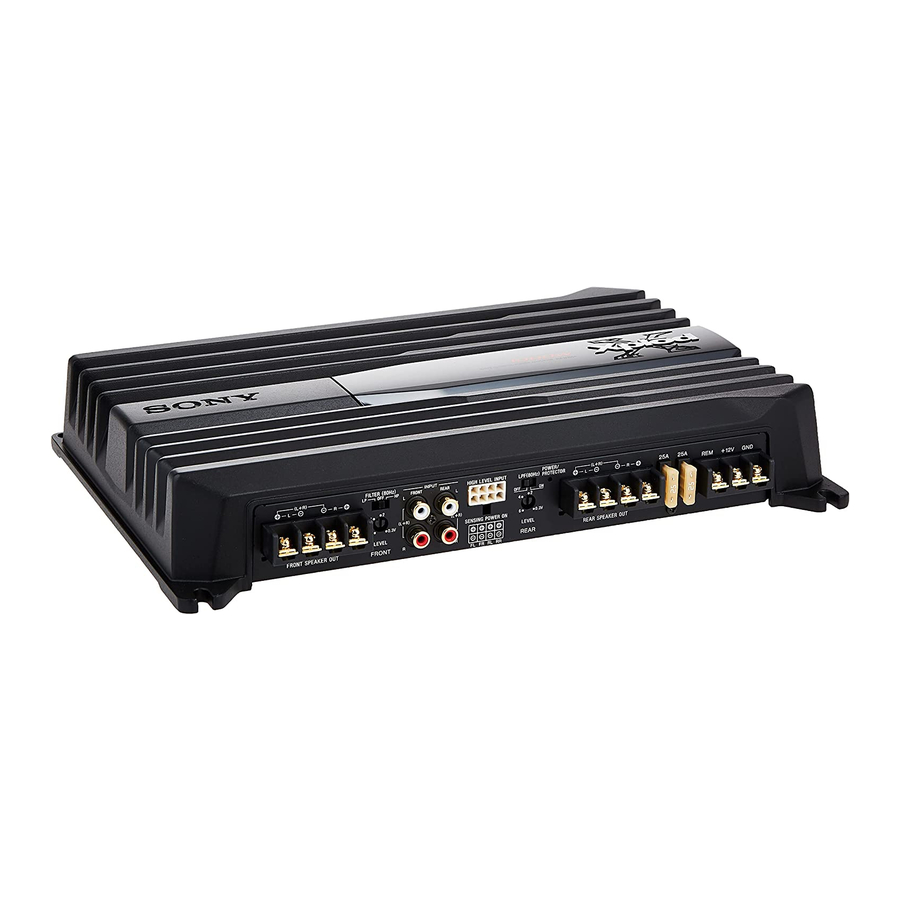
Sony XM-N1004 Service Manual
Stereo power amplifier
Hide thumbs
Also See for XM-N1004:
- Operating instructions (2 pages) ,
- Operating instructions (2 pages) ,
- Service manual (20 pages)
Table of Contents
Advertisement
SERVICE MANUAL
Ver. 1.0 2013.07
Circuit system
Inputs
Input level adjustment range
Outputs
Speaker impedance
Maximum output
Rated output
(supply voltage at 14.4 V, 20 Hz – 20 kHz, 1 % THD)
9-893-784-01
Sony Corporation
2013G33-1
©
2013.07
Published by Sony Techno Create Corporation
SPECIFICATIONS
OTL (output transformerless)
circuit
Pulse power supply
RCA pin jacks
High level input connector
(E and Indian models only)
0.3 – 6 V (RCA pin jacks)
2.8 – 12 V (High level input)
(E and Indian models only)
Speaker terminals
2 – 8 Ω (stereo)
4 – 8 Ω (when used as a bridging
amplifier)
4 Speakers: 170 W × 4 (at 4 Ω)
3 Speakers: 250 W × 2 (at 2 Ω) +
500 W × 1 (BTL, at 4 Ω)
2 Speakers: 500 W × 2 (BTL, at
4 Speakers:
70 W × 4 (at 4 Ω)
85 W × 4 (at 2 Ω)
2 Speakers: 175 W × 2 (BTL, at
XM-N1004
Frequency response
5 Hz – 50 kHz (
Harmonic distortion
0.05 % or less (at 1 kHz, 4 Ω)
Low-pass filter
80 Hz, 18 dB/oct
High-pass filter
80 Hz, 12 dB/oct
Power requirements
12 V DC car battery
(negative ground)
Power supply voltage
10.5 – 16 V
at rated output: 36 A
(4 Ω, 70 W × 4)
Remote input: 1 mA
Dimensions
Appr
(w/h/d) not incl. projecting parts
and controls
Mass
Approx. 2.7 kg not incl.
accessories
Supplied accessories
Mounting screws (4)
High level input cord (1)
(E and Indian models only)
Protection cap (1)
Design and specifications are subject to change
without notice.
STEREO POWER AMPLIFIER
Canadian Model
AEP Model
UK Model
E Model
dB)
Advertisement
Table of Contents

Related Manuals for Sony XM-N1004


Summary of Contents for Sony XM-N1004
-
Page 1: Service Manual
70 W × 4 (at 4 Ω) 85 W × 4 (at 2 Ω) Design and specifications are subject to change 2 Speakers: 175 W × 2 (BTL, at without notice. STEREO POWER AMPLIFIER 9-893-784-01 Sony Corporation 2013G33-1 © 2013.07 Published by Sony Techno Create Corporation... -
Page 2: Table Of Contents
XM-N1004 TABLE OF CONTENTS SERVICING NOTES ..........GENERAL ..............DISASSEMBLY 3-1. Disassembly Flow ............3-2. Bottom Plate Block ............3-3. MAIN Board Block ............3-4. MAIN Board ..............DIAGRAMS 4-1. Printed Wiring Board - MAIN Board - ......4-2. Schematic Diagram - MAIN Board (1/3) - ..... -
Page 3: Servicing Notes
XM-N1004 SECTION 1 SERVICING NOTES UNLEADED SOLDER NOTE FOR REPLACEMENT OF THE TRANSISTORS Boards requiring use of unleaded solder are printed with the lead- The transistors Q110, 111, 210, 211, 310, 311, 410 and 411 have free mark (LF) indicating the solder contains no lead. -
Page 4: General
XM-N1004 SECTION 2 This section is extracted GENERAL from instruction manual. Line Input Connection 3-Speaker System Conexión de entrada de línea Sistema de 3 altavoces Ligação de entrada de linha Sistema de 3 colunas ø 5 × 15 mm Full range speakers (min. 2 Ω) (×... -
Page 5: Disassembly
XM-N1004 SECTION 3 DISASSEMBLY • This set can be disassembled in the order shown below. 3-3. MAIN BOARD BLOCK 2 screw 3-1. DISASSEMBLY FLOW (+B, TT, B-TYPE, 3 1 three screws 1 three screws (+P, TT, B-TYPE, 3 (+P, TT, B-TYPE, 3 hole 3-2. -
Page 6: Diagrams
XM-N1004 SECTION 4 DIAGRAMS THIS NOTE IS COMMON FOR PRINTED WIRING BOARDS AND SCHEMATIC DIAGRAMS. • Waveforms (In addition to this, the necessary note is printed in each block.) – MAIN Board – For Printed Wiring Boards. For Schematic Diagrams. -
Page 7: Printed Wiring Board - Main Board
XM-N1004 4-1. PRINTED WIRING BOARD - MAIN Board - • : Uses unleaded solder. MAIN BOARD C844 JW183 JW27 D807 CAM004 TP15 JW28 JW29 CAM005 TH503 (CHASSIS) (CHASSIS) TP30 C819 R506 R505 TP19 TH502 TP26 C817 D803 (CHASSIS) D501 R267... -
Page 8: Schematic Diagram - Main Board (1/3)
XM-N1004 4-2. SCHEMATIC DIAGRAM - MAIN Board (1/3) - MAIN BOARD (1/3) R127 (1/3) C107 C110 100p IC803 R107 (1/3) R110 (1/3) C108 GAIN CONTROL AMP IC801 IC804 IC803 NJM4565M(TE2) R103 PRE AMP HIGH-PASS FILTER REAR (L+R) IC801 IC804 –... -
Page 9: Schematic Diagram - Main Board
XM-N1004 4-3. SCHEMATIC DIAGRAM - MAIN Board (2/3) - MAIN BOARD (2/3) R155 R158 R175 D101 R159 1.5k 1.5k DA2J10100L R163 R165 Q110 2SC5100-P 31.2 Q101 Q104 R170 POWER AMP RTAN140C-T112-1 ISA1284AS1-T112-E 32.9 SWITCH DRIVE AMP 32.3 31.2 13.7 C123... -
Page 10: Schematic Diagram - Main Board (3/3)
XM-N1004 4-4. SCHEMATIC DIAGRAM - MAIN Board (3/3) - • See page 6 for Waveforms. • See page 6 for IC Block Diagram. MAIN BOARD (3/3) TP30 MAIN BOARD Q510 Q503 R517 D515 R518 (1/3) 13.2 13.2 RT1P441C-TP-1 RT1P141C-TP-1 DA2J10100L (Page 8) 13.2... -
Page 11: Exploded Views
XM-N1004 SECTION 5 EXPLODED VIEWS Note: • -XX and -X mean standardized parts, so • The mechanical parts with no reference • Abbreviation they may have some difference from the number in the exploded views are not sup- CND : Canadian model original one. -
Page 12: Main Board Section
XM-N1004 5-2. MAIN BOARD SECTION • Bottom view D804 Q411 Q911 Q311 Q912 Q210 D803 Q910 Q410 Q211 Q913 Q310 F902 Q110 F901 not supplied not supplied CN903 Q111 not supplied CN904 (E, IND) MAIN board Note: When replacing the Q110, Q111, Q210, Q211, Q310, Q311, Q410 and Q411 on the MAIN board, refer to “NOTE FOR... -
Page 13: Electrical Parts List
XM-N1004 SECTION 6 MAIN ELECTRICAL PARTS LIST Note: • Due to standardization, replacements in • CAPACITORS When indicating parts by reference num- uF: μF the parts list may be different from the ber, please include the board name. parts specifi ed in the diagrams or the com- •... - Page 14 XM-N1004 MAIN Ref. No. Part No. Description Remark Ref. No. Part No. Description Remark C451 1-116-868-11 ELECT 47uF < JACK > C452 1-162-923-11 CERAMIC CHIP 47PF CNJ101 1-779-078-21 JACK, PIN 4P (INPUT FRONT/REAR) C453 1-162-919-11 CERAMIC CHIP 22PF C454 1-118-347-11 CERAMIC CHIP 0.1uF...
- Page 15 XM-N1004 MAIN Ref. No. Part No. Description Remark Ref. No. Part No. Description Remark JC14 1-216-296-11 SHORT CHIP Q309 6-552-810-01 TRANSISTOR KTA1023-Y-AT/P JC15 1-216-296-11 SHORT CHIP Q310 8-729-024-79 TRANSISTOR 2SC5100-P (See Note) JC16 1-216-296-11 SHORT CHIP JC17 1-216-296-11 SHORT CHIP...
- Page 16 XM-N1004 MAIN Ref. No. Part No. Description Remark Ref. No. Part No. Description Remark R106 1-218-871-11 METAL CHIP 0.5% 1/10W R254 1-216-222-00 METAL CHIP 1/8W R107 1-218-871-11 METAL CHIP 0.5% 1/10W R255 1-216-841-11 METAL CHIP 1/10W R109 1-218-882-11 METAL CHIP 0.5%...
- Page 17 XM-N1004 MAIN Ref. No. Part No. Description Remark Ref. No. Part No. Description Remark R367 1-216-134-00 METAL CHIP 1/8W R516 1-216-845-11 METAL CHIP 100K 1/10W R368 1-216-134-00 METAL CHIP 1/8W R517 1-216-844-11 METAL CHIP 1/10W R369 1-205-991-11 ENCAPSULATED COMPONENT 0.1...
- Page 18 XM-N1004 MAIN Ref. No. Part No. Description Remark Ref. No. Part No. Description Remark R950 1-216-833-11 METAL CHIP 1/10W PARTS FOR INSTALLATION AND CONNECTIONS ************************************** R951 1-216-833-11 METAL CHIP 1/10W R953 1-216-833-11 METAL CHIP 1/10W X-2108-372-1 SCREW SUB ASSY (Mounting screws) (E, IND) (Tapping Screw (DIA.
- Page 19 XM-N1004 MEMO...
-
Page 20: Revision History
XM-N1004 REVISION HISTORY Checking the version allows you to jump to the revised page. Also, clicking the version at the top of the revised page allows you to jump to the next revised page. Ver. Date Description of Revision 2013.07...
Need help?
Do you have a question about the XM-N1004 and is the answer not in the manual?
Questions and answers