Table of Contents
Advertisement
Advertisement
Table of Contents

Related Manuals for Panasonic KX-T2373MXW


Summary of Contents for Panasonic KX-T2373MXW
- Page 1 ORDER NO. KM40108848C3 Telephone Equipment KX-T2373MXW Integrated Telephone System White Version (for Asia, Middle Near East and other areas) © 2001 Kyushu Matsushita Electric Co., Ltd. All rights reserved. Unauthorized copying distribution is a violation of law.
-
Page 2: Table Of Contents
KX-T2373MXW CONTENTS Page Page 1 LOCATION OF CONTROLS 9 BLOCK DIAGRAM 2 CONNECTION 10 BLOCK DIAGRAM (IC 1) 2.1. Connecting the Handset/Telephone Line Cord 10.1. Communication ICs 2.2. Connecting a Communication Device 11 CIRCUIT OPERATION 3 SETTINGS 11.1. Bell Detector Circuit 3.1. -
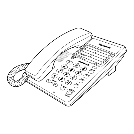
Page 3: Location Of Controls
KX-T2373MXW 1 LOCATION OF CONTROLS... -
Page 4: Connection
2.1. Connecting the Handset/Telephone Line Cord After connection, lift the handset to check for a dial tone. · Use only a Panasonic Handset for the KX-T2373MXW. 2.2. Connecting a Communication Device If you connect a communication device (computer, modem, fax, answering machine, etc.) to the telephone line, you can connect it through this unit using the DATA jack. -
Page 5: Settings
KX-T2373MXW 3 SETTINGS 3.1. Selecting the Dialing Mode You can select the dialing mode by programming. If you have touch tone service, set to "Tone". If rotary or pulse service is used, set to "Pulse". Your phone comes from the factory set to "Tone". -
Page 6: Special Features
KX-T2373MXW 4 SPECIAL FEATURES 4.1. FLASH Button Pressing allows you to use special features of your host PBX such as transferring an extension call or accessing special telephone services (optional) such as call waiting. 4.2. Selecting the Flash Time The flash time depends on your telephone exchange or host PBX. You can select the following flash times: "80, 90, 100, 110, 200, 250, 300, 400, 600, 700 ms (milliseconds)". -
Page 7: Setting The Pin Code
The factory preset Pin code is "1111". Make sure that a call is not put on hold. Please write down your Pin code. If you forget your Pin code, consult your nearest Panasonic service center. -
Page 8: Dial Lock
KX-T2373MXW 4.4. Dial Lock You can prevent others from making a call to any number except the one pre-programmed in the memory of the EMERGENCY button. Once you locked the dialing buttons, even emergency numbers cannot be dialed. Only incoming calls are accepted until the dial lock is canceled. -
Page 9: Call Restriction
KX-T2373MXW 4.5. Call Restriction You can prevent the unit from dialing phone numbers beginning with specified digit(s) (1 digit or 2 digits). Phone numbers with the restricted leading digits cannot be dialed out. 4.5.1. To Set the Call Restriction Make sure that a call is not put on hold. -
Page 10: How To Release The Establishment Of Dial Lock
KX-T2373MXW 4.7. How to Release the Establishment of Dial Lock After this procedure, you will be able to establish a new password. How to release the establishment of dial lock. -
Page 11: Disassembly Instructions
KX-T2373MXW 5 DISASSEMBLY INSTRUCTIONS Ref. No. Procedure Shown in Fig —. To remove —. Remove —. Lower Cabinet Screws (2.6×12) ... . . (A)×5 1 ~ 2 Printed Circuit Board... -
Page 12: How To Replace Flat Package Ic
KX-T2373MXW 6 HOW TO REPLACE FLAT PACKAGE IC 6.1. Preparation · SOLDER Sparkle Solder 115A-1, 115B-1 or Almit Solder KR-19, KR-19RMA · Soldering iron Recommended power consumption will be between 30 W to 40 W. Temperature of Copper Rod 662 ± 50°F (350 ± 10°C) (An expert may handle between 60 ~ 80 W iron, but beginner might damage foil by overheating.) -
Page 13: Cpu Data
KX-T2373MXW 7 CPU DATA 7.1. IC801... -
Page 14: Speakerphone Ic Data
KX-T2373MXW 7.2. Speakerphone IC Data Name Description A resistor to ground provides a reference current for the transmit and receive attenuators. A resistor to ground determines the nominal gain of the transmit attenuator. The transmit channel gain is inversely proportional to the RTX resistance. -
Page 15: Terminal Guide Of Ic S Transistors And Diodes
KX-T2373MXW 8 TERMINAL GUIDE OF IC’S TRANSISTORS AND DIODES... -
Page 16: Block Diagram
9 BLOCK DIAGRAM... -
Page 17: Block Diagram (Ic 1)
KX-T2373MXW 10 BLOCK DIAGRAM (IC 1) 10.1. Communication ICs... -
Page 18: Circuit Operation
KX-T2373MXW 11 CIRCUIT OPERATION 11.1. Bell Detector Circuit When the bell signal is input between T/R, the signal are outputted at the speaker via the following path: Tel line → R1/C1 → D1 → Pin 1 of IC1 → Pin 8 of IC1 → C6 → T1 → C625 → Speaker 11.2. -
Page 19: Module Block Diagram
KX-T2373MXW 11.3. MODULE BLOCK DIAGRAM 11.3.1. Speakerphone Circuit 11.3.1.1. Function The circuit controls the automatic switching of the transmitted and received signals, to and from the telephone line, when the unit is used in the hands -free mode. 11.3.1.2. Circuit Operation The speakerphone can only provide a one-way communication path. - Page 20 KX-T2373MXW 11.3.2. Telephone Line Interface 11.3.2.1. Circuit operation · On hook Q101 is open, Q101 is connected as to cut DC loop current and cut the voice signal. · Off hook Q101 turns on thus providing an off-hook condition (active DC current flow through the circuit) and the following signal flow id for the DC loop current.
- Page 21 KX-T2373MXW 11.3.3. Tone Detect This circuit is used to sense the status of the line (busy tone or dial tone) during Auto Redial. 11.3.3.1. Circuit operation D101 → Q101 → C201 → R201 → R205 → Pin 5 of IC201 → Pin 1 of IC201 → D202 → R208 → Q201...
- Page 22 KX-T2373MXW 11.3.4. Inializing Circuit 11.3.4.1. Function This circuit is used for to initialize the microcomputer when it incorporates batteries. 11.3.4.2. Circuit operation When the batteries is inserted into the unit, then the voltage is shifted by D304 and power is supplied to the CPU. The set can...
-
Page 23: Trouble Shooting Guide
KX-T2373MXW 12 TROUBLE SHOOTING GUIDE 12.1. Service Hints SYMPTOM CURE Dead Check IC801, X801, X802 Can’t hear the voice from handset. Check Q109, Q405, Q406. No voice transmit. Check Q421, Q424, Q108. Can’t tone dial. Check IC801, R921, R922, R923 and C923. -
Page 24: Tone Dialing Problems (Hnadset)
KX-T2373MXW 12.3. Tone Dialing Problems (Hnadset) 12.4. No Ringing Sound When Ring Signal is Input. -
Page 25: Cabinet And Electrical Parts Location
KX-T2373MXW 13 CABINET AND ELECTRICAL PARTS LOCATION... -
Page 26: Accessory And Packing Materials
KX-T2373MXW 14 ACCESSORY AND PACKING MATERIALS... -
Page 27: Replacement Parts List
KX-T2373MXW 15 REPLACEMENT PARTS Ref. Part No. Part Name & Description Remarks PQKK10105Z1 BATTERY COVER LIST PQKE10070Z3 HANGER PQJC10044Z BATTERY TERMINAL This replacement parts list is KX-T2375MXW only. PQJC10045Z BATTERY TERMINAL PQJC313Z BATTERY TERMINAL 1. RTL (Retention Time Limited) PQJC314Z... - Page 28 KX-T2373MXW Ref. Part No. Part Name & Description Remarks Ref. Part No. Part Name & Description Remarks PQSX03 PQSX10187Z SWITCH R421 ERJ3GEYJ182 1.8k SW101 PQSH2B105Z SWITCH R422 ERJ3GEYJ153 (JACKS) R423 ERJ3GEY0R00 JJ101 PQJJ1T020Z JACK R424 ERJ3GEYJ334 330k JJ102 PQJJ1T020Z JACK...
-
Page 29: Accessories And Packing Materials
KX-T2373MXW Ref. Part No. Part Name & Description Remarks Ref. Part No. Part Name & Description Remarks ECEA1HUR22 0.22 C905 ECUV1H103KBV 0.01 ECUV1H822KBV 0.0082 C921 ECUV1H332KBV 0.0033 ECEA1HKA010 C922 ECUV1H152KBV 0.0015 C101 ECKD2H681KB 680p C923 ECUV1H152KBV 0.0015 C102 ECKD2H681KB 680p... -
Page 30: For Schematic Diagram (Schematic Diagram)
KX-T2373MXW 16 FOR SCHEMATIC DIAGRAM (SCHEMATIC DIAGRAM) 1. DC voltage measurements are taken with electronic voltmeter from negative terminal. (Add 40 mA to telephone line from the loop simulator.) 2. This schematic diagram may be modified at any time with the development of new technology. -
Page 31: Memo
KX-T2373MXW 16.1. MEMO... -
Page 32: Schematic Diagram
KX-T2373MXW 17 SCHEMATIC DIAGRAM IC601 IC651 (5.8V) Beep IC903 IC801 DTMF Hold Music 3.7V (3.7V) - Page 33 KX-T2373MXW (6.3V) 4.2V (5.8V) (6.3V) IC201 Battery Low 3.8V 4.5V IC304 IC302 3.7V (3.7V) 3.9V IC303 (5.7V) The voltage during ON-Hook is indicated. ) shows the voltage during OFF-Hook. Headset Set & Headset Set Incoming Signal Speaker Phone Incoming Signal Headset Set &...
- Page 34 KX-T2373MXW...
-
Page 35: Circuit Board And Wiring Connection Diagram
KX-T2373MXW KXT2375MXW Printed in Japan...