
Related Manuals for Strong Super Trouper


Summary of Contents for Strong Super Trouper
- Page 1 FOLLOW SPOTLIGHT INSTRUCTION MANUAL Equipment Type 7201156 • Rev. October 2010 4350 McKinley Street • Omaha, Nebraska 68112 USA Tel (402) 453-4444 • Fax (402) 453-7238 • www.strong-lighting.com...
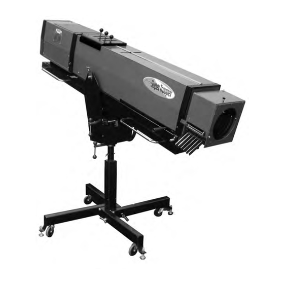
- Page 3 PREFACE THE STRONG XENON SUPER TROUPER is a direct current follow spotlight ® system complete with a xenon lamphouse, power supply, optical system, and a floor stand and yoke assembly. An optional six-color, self cancelling boomerang (Order No. 7201188; see Figure 7) may be ordered with new equipment, or it can be added at a later date. ONLY THE SPECIAL XENON POWER SUPPLIES manufactured by Strong I nternational can be used with the xenon spotlight. For installation and operation of the power supply, see the instruction manual furnished separately. THE XENON LAMPHOUSE utilizes a deep ellipse dichroic metal reflector designed to operate in a fixed position with a horizontally mounted xenon bulb as the light source. A heat filter is located in the front of the lamphouse to reduce the heat at the optical system and color boomerang. ONLY XENON BULBS designed for horizontal operation should be used in this spotlight. The lamphouse is designed for use with the standard 2000 watt horizontal theatre bulb, and an optional Adapter Kit (Order No. 7201192) allows use of 1000 and 1600 watt bulbs. See the listing in this manual for the approved types and necessary adapters. ADJUSTMENT CONTROL for positioning the xenon bulb is located at the rear of the lamp h ouse. The adjustments are for the horizontal, vertical, and focus control of the bulb.
- Page 4 LAMPHOUSE - POWER SUPPLY Interconnection Diagram LAMPHOUSE (Connections Pre-wired) MS CONNECTOR Wire No. Grnd Lamphouse Cable Assembly SYSTEM MUST BE GROUNDED All wiring must conform to local codes; shield lamphouse cable in conduit if required. XENON POWER Check Slide Switch (below) on Power SUPPLY Supply for correct “SPOT”...
- Page 5 INSTALLATION AND SETTING UP SPOTLIGHT THE XENON SUPER TROUPER is shipped in sections which must be a ssembled. The Folding Base Stand Assembly 65826000 (see Figure 6) is shipped collapsed, and requires only folding down and pinning the four base legs. WHEN INSTALLED in a permanent location, the leveling feet must be removed, and the clearance holes in the base leg brackets used for hardware (user supplied) to bolt the base to the floor or platform. If it is desired to have the unit portable, when operating, the leveling feet must be adjusted down until the weight of the spotlight has been shifted from the casters to the leveling feet. THE INNER TUBE and support yoke has three holes to permit adjusting the height of the spotlight. The three holes are on four-inch centers and will allow an optical height of a pproximately 53 inches, 57 inches, and 61 inches above floor level to the optical center of the lamphouse and lens system. The leveling feet may be adjusted through an additional two inch range. Insert the height loca- tion pin (Figure 5, Item 16) through the hole in the outer tube and one of the holes in the inner tube. THE HORIZONTAL SWING and vertical tilt locking knobs are on the right hand (operating) side of the yoke assembly. Tighten both of these locking devices (Figure 6, Items 19 & 21) securely before a ttempting to place the lamphouse and lens system on the support yoke. PLACE THE LAMPHOUSE and lens system on the yoke assembly (Figure 6, Item 4), with the spot size control handle to the right hand (operating) side, the same as the locking controls on the yoke. Line up the four mounting holes in the bottom of the base rail with four slotted holes in the support yoke and secure with the four 5/16-18 wing screws. There are (2) sets of four mounting holes to insure correct balance of the spotlight with or without the optional color boomerang. An optional Counterweight Kit (7201191) is also available for setting concise balance adjustments. THE OPTIONAL COLOR BOOMERANG (7201188) mounts to the front opening of the optical system on three studs protruding from the front of the optical system housing. Secure the boomerang using the (3) screws provided, and install the safety cable between the boomerang housing and the spotlight frame. ATTACH THE LAMPHOUSE CABLE CONNECTOR to the receptacle on the xenon power supply. Align the pins before tightening the locking ring. Do not energize the power supply before first completing the bulb installation procedure. CHECK THE “CONS/SPOT” SLIDE SWITCH on the xenon power supply cabinet and verify that it has been placed in the appropriate “SPOT” position. See the illustration on the inside front cover of the Xenon Power Supply instruction manual.
-
Page 6: Safety Procedures
SAFETY PROCEDURES THE XENON BULB is highly pressurized. When ignited, the normal operating temperature of the bulb increases the pressure to a level at which the bulb may explode if not handled in strict accordance to the manufacturer’s operat i ng instructions. The bulb is stable at room temperature, but may still explode if dropped or otherwise mishandled. REFER bulb replacement and service to QUALIFIED PERSONNEL with adequate protec- tive clothing (face shield, clean cotton gloves, welder’s jacket). For routine lamphouse service, observe the following rules: 1. Allow the bulb to cool to room temperature before opening the lamphouse. Put on protective clothing described above. 2. De-energize the xenon power supply at the AC source before opening the lamphouse compartment. 3. When possible, encase the bulb in its protective cover when cleaning or servicing the lamphouse interior. The bulb, when outside the lamphouse, must be encased in the cover. 4. Clean the bulb after it has cooled to room temperature. Do not touch the quartz envelope of the bulb; fingerprints will burn in and create hot spots which may shorten bulb life. If fingermarks are made, they should be care f ully removed with methyl alcohol and cotton prior to bulb operation. 5. Never view an ignited bulb directly. BLINDNESS OR PERMANENT EYE DAMAGE MAY BE INCURRED. - Page 7 1. Fade-Out Mechanism Control Lever 7. Spot Focus Control Knob 2. Masking Shutter (Chopper) Control Lever 8. Leveling Foot 3. Iris Control Lever 9. Height Adjust Pin 4. Boomerang Mounting Stud, Upper* 10. Horizontal Swing Control Lever 5. Spot Size Control Handle 11. Vertical Tilt Control Lever 6. Boomerang Mounting Stud, Lower* 12. Lifting Strap * Color Boomerang optional; see Figure 7 XST/005...
-
Page 8: Exhaust System Installation
EXHAUST SYSTEM INSTALLATION IF THE SPOTLIGHT is installed in a closed booth, it is recommended to vent the lamphouse exhaust to outside atmosphere to remove the heat from the booth. An optional lamphouse top cover plate with an exhaust stack (Part No. 7201222) may be ordered from Strong and installed in place of the standard top cover plate (see Parts List, Figure 2, Item 27). THE EXHAUST STACK of the optional lamphouse cover plate is designed to fit a six-inch diameter duct. The exhaust system must be designed and installed is a manner as to elimi- nate any possibility of a down draft or of rain dripping into the lamphouse. The exhaust fan must be capable of removing 750 lineal feet per minute (150 cfm) of air from each lamphouse. TO PERMIT MOVEMENT of the follow spotlight, install a section of six-inch diameter, non-flammable, flexible ducting between the lamphouse exhaust stack and the projection booth exhaust system. Two screw holes in the exhaust stack can be used to secure the ducting with #6 self-tapping sheet metal screws. IF ADDITIONAL BULB COOLING is required (i.e. 50 Hertz power source), an optional Exhaust Blower Assembly (Part No. 7201036; see Figure 8) may be mounted to the existing top cover of the lamphouse. When connecting the blower leads, make certain the wires are dressed behind the reflector support casting to prevent heat damage. This blower assembly exhausts into the surrounding air and does not allow connection to a ducted exhaust system. - Page 9 1. LAMP Switch (ON-OFF) 2. Ammeter 3. Air Intake, Blower 4. Cover, Bulb Adjust Controls 5. Top Cover, Lamphouse 6. Elapsed Hour Meter XST/007...
- Page 10 XST/008...
-
Page 11: Bulb Installation
BULB INSTALLATION CAUTION: OBSERVE ALL SAFETY PROCEDURES. Put on the protective face mask. Wear clean cotton gloves to prevent marking the quartz envelope of the bulb with fingerprints. REMOVE THE TOP COVER of the lamphouse by removing the four Holt head (tamperproof) screws with the special screwdriver provided. NO BULB ADAPTERS are required to install the 2000 watt bulb in the Xenon Super Trouper lamphouse. Components and adapters required to install the 1000 watt or 1600 watt bulb in the lamphouse are available in an optional Adapter Kit (Part No. 7201192). See the Bulb Adapter illustration on the facing page for the cor r ect adapters and method of assembly. 1000 & 1600 Watt Bulb Installation DISMOUNT AND REMOVE the front bulb mounting ring assembly from the air duct casting in front of the reflector and replace it with the smaller bulb support yoke casting included in the 7201192 Bulb Adapter Kit. Install the 65148000 cathode clamp in place of the standard 2 kW clamp. Remove the rear bulb support collet assembly (nylon rod and brass socket) from the bulb focus assembly behind the reflector and replace it with the collet assembly included in the Bulb Adapter Kit. ASSEMBLE THE REQUIRED ADAPTERS to the 1000 or 1600 watt bulb prior to inserting the bulb into the lamphouse. Be very careful not to apply any strain on the quartz envelope when installing adapters. Handle the bulb by its metal end caps only. Screw the threaded cathode adapter onto the negative stud so it seats firmly against the shoulder of the cathode (-) end cap. Apply torque using the pins on the cathode end cap. Slip the anode adapter with set screw over the positive stud, up to the shoulder of the anode (+) end cap. Tighten all fasteners securely to insure a good electrical connection. REMOVE THE PLASTIC PROTECTIVE COVER from the xenon bulb only if nec- essary. Insert the bulb through the top of the lamphouse, between the reflector support and the front casting. Pass the anode (+) end of the bulb through the hole in the reflector, taking care not to touch the surface of the reflector. - Page 12 BULB INSTALLATION (continued) 2000 Watt Bulb Installation THE 2000 WATT bulb mounting components include a shock mount support at the front of the lamphouse. Insert the 2000 watt bulb through the top of the lamphouse, passing the anode (+) end through the hole in the reflector. Pass the anode pin as far as possible to the rear of the lamphouse to permit sliding the cathode (-) end cap through the ring of the shock mount. Temporarily removing the 65131000 anode clamp from the brass socket of the collet allows added clearance for the bulb. Gently rotating or turning the bulb while sliding the cathode end cap through the shock mount will slightly compress the coil spring and prevent stripping the spring from its channel in the ring. REPLACE THE ANODE CLAMP over the rear bulb socket. Insert the anode (+) pin of the bulb into the rear support collet, and firmly tighten the socket head clamping screw. Slide the 65410000 cathode contact clamp over the cathode (-) pin and tighten securely. AN ALTERNATE METHOD of installing the 2000 watt bulb is to dismount the 83748000 shock mount ring from the front bulb support assembly by removing the 4100620 socket head clamping screw. Slide the ring over the cathode (-) end cap of the bulb, and install the bulb by inserting the anode (+) end cap through the reflector center hole and seating the anode pin into the rear sup p ort collet. Remount the ring to the 83364000 base bracket of the front bulb support using the socket head screw. DO NOT dismount or reposition the factory-aligned base bracket. Secure the anode (+) clamping screw; install and tighten the cathode (-) contact clamp. THE SOCKET HEAD SCREW which mounts the 83748000 bulb support ring to the 83364000 base bracket must be tightened securely enough to clamp the upright bulb support ring in a vertical (90°) position and prevent its tilting forward or back as the bulb is focused. The end cap of the bulb should touch only the coils of the 83410000 shock mount spring to allow the bulb to slide forward and back with a minimum of friction and no stress on the quartz envelope. OBSERVE THE POSITION of the Trigger Wire on the xenon bulb relative to the point where the bulb passes through the center hole of the reflector. Some bulb manufacturers attach one end of the trigger wire to the anode end cap; if this trigger wire approaches the reflector too closely,...
- Page 13 XST/011...
-
Page 14: Operation
OPERATION REMOVE THE PLASTIC COVER from the xenon bulb. Do not ignite the lamp with the protective shipping cover on the bulb. A GLASS HEAT FILTER is supplied to reduce the temperature at the optical system and color gels. This filter is a narrow glass strip that covers only the center portion of the beam. Insert the heat filter in the bracket provided on the inside of the lam p house at the front opening (see Figure 2, Item 2). Place the filter in position with the coated surface facing the bulb. The coated surface is indicated by a small XX or other marking. To prevent damage to optical system components, do not operate the spotlight with the filter removed or reversed. SECURE THE LAMPHOUSE COVER with the (4) tamperproof screws using the special screwdriver provided. The cover must be securely in position to actuate the interlock switch and permit lamp ignition. CLOSE THE CIRCUIT BREAKER on the xenon power supply to energize the power supply. The blowers in the power supply and in the lamphouse will start; the lamphouse blower will actuate the air intake interlock switch to permit bulb ignition. The lamp and power supply blowers will operate continuously until the xenon power supply is de-energized. PLACE THE LAMP SWITCH in the ON position and the xenon bulb will ignite. Allow a few minutes for the current to stabilize, and read the lamphouse ammeter. The bulb must be operated within the current range specified by the bulb manufacturer. The ranges for the xenon bulbs approved for use with the Xenon Super Trouper are as follow: WATTAGE NOMINAL CURRENT DO NOT EXCEED 1000 50 A. 58 A. 1600 65 A. 70 A. 2000 75 A. 90 A. - Page 15 THE THUMB SCREWS to the left and right of the focusing control lock the horizontal and vertical position of the bulb. BULB ADJUSTMENT CONTROLS Thumb Screw Focus Control Focus Lockscrew TWO METHODS, details following, are recommended to align the bulb in order to project the best light to the stage. MOVE THE SPOT SIZE CONTROL HANDLE on the large lens carriage to the forwardmost position to project the smallest spot possible. Set the iris, choppers, and dimming control to their full open positions. Project the spot to a wall or similar flat perpendicular surface opposite the spotlight position. TURN THE CENTER FOCUS CONTROL counterclockwise until a small black spot is projected on the wall. It may be well to run this adjustment both directions to permit positive identification of the dark spot. LOOSEN THE TWO THUMB SCREWS to the left and right of the focus control just enough to permit manual movement of complete control assembly. Move the control as s embly around the two thumb screws and observe the smooth dark shadow of the bulb electrode inside the shaded circle of the reflector center opening. The shadow of the electrode must be centered in the projected opening of the reflector. MOVE THE CONTROL ASSEMBLY around the thumb screws until the dark elec- trode shadow is as round as possible to project. It may be necessary to again rotate the focus control to define the electrode shadow. AFTER THE ELECTRODE SHADOW is as even around the outside as possible, tighten the two thumb screws to lock this adjustment in place, and rotate the focus control to ob t ain the brightest light with the best light distribution. Turn the spot focus control knob, located on the front of the lens mechanism, to sharpen the edge of the spot.
- Page 16 the “hot spot” is centered in the projected spot, lock the adjustment control in position with the two thumb screws and rotate the focus control to obtain a spot with an even distribution of light. Turn the spot focus control knob at the front of the lens mechanism to sharpen the edge of the spot. THIS ADJUSTMENT should not be disturbed until the xenon bulb is replaced. At this time it will be necessary to repeat the alignment procedure. REPLACE THE REAR COVER PANEL over the bulb adjustment control mechanism. Secure using the plastic fasteners. BECAUSE OF MANUFACTURING TOLERANCES and normal bulb aging, it may be necessary to operate one lamp at slightly higher or lower current than others to balance light ouput between multiple units. These adjustments are made at the xenon power supply. TO EXTINGUISH THE ARC, place the LAMP switch in the OFF position. The blower in the lamphouse will continue running until the xenon power supply is de-energized. Allow the blower to operate and cool the bulb for at least five minutes after extinguishing. This measure will prolong bulb life. HANDLING THE SPOTLIGHT GENERALLY THE BEST POSITION for the operator to stand is near the center of the spotlight, on the right hand side, although the angle of tilt and the size of the porthole may alter the position for the most convenient operation. EACH OPERATOR will, after a few minutes of operation, generally develop his own system and position for operating the unit. THE HORIZONTAL SWING LOCK LEVER and vertical tilt lock lever located on the base assembly can be set to give the desired amount of friction on the spotlight swing to suit the individual operator. An optional counterweight assembly (Part No. 7201191; see Figure 7) allows adding or removing weights for concise adjustment of the spotlight balance. THE LENS CARRIAGE FRICTION BRAKE is a nylon drag screw and locknut located on the outrider of the large lens carriage (see Figure 4, Items 16 & 17), and is preset at the factory for most satisfactory opera t ion. Individual requirements may vary, and the brake can be adjusted to best suit the operator or to allow for a steep downward angle. Remove the color boomerang and lens mechanism hous i ng, loosen the nylon lock nut and tighten or loosen the screw on the friction brake to apply the desired tension. Tighten the lock nut and replace the housing and boomerang.
- Page 17 OPERATION OF COLOR BOOMERANG THE OPTIONAL COLOR BOOMERANG is equipped with six color filter holders. Additional filter holders (51928000 & 51376000) can be supplied by your Strong dealer. TO OPERATE INDIVIDUAL COLOR FILTERS, lower the desired filter selec t or lever. A rocker catch located in the color disc housing holds the filter in position. TO RELEASE A COLOR, push either filter release arm upward or engage another color, thus releasing the previous color automatically. NOTE: WHEN PLACING COLOR FILTERS in the boomerang, the less dense colors (amber, pink) should be placed in the holders toward the rear of the boomerang (closer to the arc), and those of greater density (red, green) should be placed in the holders toward the front of the boomerang (away from the arc). Use RoscoLux (or equivalent) high temperature filters. ® COLOR TEMPERATURE REDUCTION FILTERS, required for use with televi s ion and videotape, are available from theatrical supply dealers. PROVISION IS MADE for “stowing” color holders for transport. When stowed, the color holders are protected from breakage or other damage caused by moving the spotlight. To enable operation of the color boomerang, detach the lower thumbscrew securing the hinged portion of the boomerang housing and fold the panels upward. This allows the color holders to drop into a “deployed” position for normal operation. An upper thumbscrew allows locking the hinged panels in the upper position. To again stow the color holders for transport, raise all six color holders to their engaged position, loosen the upper lockscrew, unfold the hinged boomerang housing, and secure in the lower position.
- Page 18 OPERATION OF OPTICAL SYSTEM THE IRIS CONTROL is the front lever which projects through the top of the o ptical system housing. When this lever is to the right (as viewed from the rear of the unit), the largest aperture is provided. Smaller apertures are selected as the lever is moved to the left. THE SPOT SIZE CONTROL HANDLE is located on the right hand side of the optical system just above the base rail. A variation of spot sizes from full flood to small spot can be obtained by moving the spot size control handle from one extreme to the other. Beam in t ensity is increased by this optical system when reducing from flood to spot, and maximum i ntensity is reached when the spot size control handle is in the extreme forward position. THE MAXIMUM FLOOD SPOT is obtained with all three beam shape control levers to the right (toward operating side) for the largest aperture, and with the spot size control handle moved as far to the rear as possible. SMALLER SIZED SPOTS are projected as the spot size control handle is moved for- ward. Most of the spot sizes needed will be produced with the iris in its maximum open position. FOR A “HEAD SPOT,” or any spot smaller than can be obtained with the spot size control handle in its extreme forward position, shift the iris control lever to the left (away from operating side) for a smaller aperture. The iris control lever should always be returned to its ex- treme right position before the spot size control handle is again moved to obtain larger spots. A “DIFFUSED” SPOT is projected by sliding the spot size control handle backward toward its “flood” setting while closing the iris (aperture selector lever toward left). A “diffused” spot is a soft-edged spot with low light intensity and is seldom required. THE MASKING SHUTTER (chopper) lever is the middle lever projecting through the top of the optical system housing. The masking shutter blades are operated by this lever to shape the projected spot to a rectangle, strip spot, or dousing. THE DISENGAGED POSITION of the masking shutter lever is to the extreme right (toward operating side) and varying degrees of masking to complete cutoff are obtained by moving the lever to the left (away from operating side). THE ANGLE of the masking shutter blades can be adjusted to compensate for the horizontal projection angle. Remove the color boomerang and optical system housing, and loosen the screws holding each of the masking shutter blades enough to allow movement. Ignite the bulb and adjust the angle of the bottom blade by tapping with a screwdriver so its projected edge lies parallel to the footlights. Tighten the screw. Operate the masking shutter lever to close the blades. Adjust the upper blade to close in line with the bottom blade and tighten the screw.
- Page 19 OPERATION OF OPTICAL SYSTEM (continued) THE FADEOUT MECHANISM AND DOUSER CONTROL is the rear lever projecting through the top of the optical system cover. This lever controls the intensity of light from complete fadeout when the lever is to the left, to full intensity when the lever is to the right. THE SPOT FOCUSING CONTROL KNOB is located on the operating side of the optical system at the forward end above the base rail. This control is used to position the lenses of the optical system for the length of throw. When making an adjustment, rotate the spot focusing control knob until the sharpest edge is obtained on the projected spot. IF UNABLE TO ACHIEVE A “HARD” EDGE on the spot, the ribbon joining the lenses (see Figure 4, Item 12) can be lengthened or shortened by repositioning the cotter pin attaching the ribbon to the small lens carriage; see Figure 4, Item 25. The ribbon may also require resetting if the spotlight is moved from its original location to a new position with a different throw distance. A SLOT in the lens mechanism housing, between the beam shaping control levers and the front lens, allows insertion of special media such as frost gels. Additional gel frames (Part No. 83374000) may be ordered from Strong dealers. 7201304 Gobo 7201305 GOBO HOLDER KIT (Optional) Holder ADDITION of the 7201305 Gobo Holder Kit permits the insertion of gobos to project patterns in the spotlight beam. Patterns are loaded into the 7201304 Gobo Holder which is in- serted through the top of the optical system housing and into slide channels. The gobo holder is designed to accommodate Size “D” patterns. A stop screw centers the pattern in the light beam. THE GOBO HOLDER must be inserted as shown, with the handle grip to the left, and the pattern retaining flap in the rear. This permits free operation of the iris lever, and prevents the flap from catching on the rubber light baffle. EXTRA gobo holders permit preloading patterns into holders when two or more patterns are used in a single perfor- mance. Additional 7201304 Gobo Holders may be ordered Stop Screw through an authorized Strong Dealer.
-
Page 20: Maintenance
MAINTENANCE THE XENON SUPER TROUPER SPOTLIGHT requires very little maintenance to keep it in good working order. THE REFLECTOR and heat filter glass should be cleaned periodically with a clean, soft, lint free cloth to remove any dust from the reflective surface. Do not use abrasive cleaners. CHECK ALL ELECTRICAL CONNECTIONS periodically for tightness, espe c ially the bulb connections and other leads in the DC circuit. THE XENON LAMPHOUSE requires no lubrication other than the blower motor. This should be lubricated with two or three drops of non-detergent oil at each oil hole every six months. The lamphouse cover must be removed to expose the oil holes. THE XENON BULB should be checked occasionally for presence of foreign material on the quartz envelope. Any dirt or other foreign material must be removed immediately. CAUTION: Observe all safety procedures when working around the exposed bulb. THE INSIDE OF THE LAMPHOUSE and the blower should be cleaned peri o dically, depending on the dust conditions at each installation. The blower requires cleaning to remove dust build up which accumulates over a period of time. Keep the air inlet grille clean to permit free air flow. AN ARC STABILIZATION MAGNET is mounted to the base of the lamphouse below the reflector and is required by xenon bulb manufacturers for the correct operation of the 2000 watt horizontal bulb. If removed for any reason, it must be replaced with the NORTH seeking pole (unpainted) toward the right (operator’s) side of the lamphouse. The presence of this magnet is not detrimental to the operation of 1000 or 1600 watt bulbs, if used in place of the 2000 watt bulb. THE OPTICAL SYSTEM LENSES must be kept clean to prevent any light reduc- tion in the projected spot. To gain access to the lenses, tighten the horizontal swing and vertical tilt locking clamps, and remove the color boomerang and optical system housing. CLEAN THE PROJECTION LENS and large lens with any cleaner approved for use on coated projection lenses. If the projection lens is removed for cleaning, note the direction of the lens when reinstalling. The lens tube is marked with arrows indicating the end nearest the iris. WHEN TRANSPORTING the spotlight, it is recommended that the xenon bulb be removed and placed in its original shipping carton with the cover on to insure against breakage. If the spotlight is equipped with the standard 2 kW bulb shock mount, the unit may be transported with the bulb installed, assuming reasonable caution is exercised. Under no circumstances should the unit be moved until the bulb has cooled to room temperature. XST/018... - Page 21 LAMPHOUSE SCHEMATIC XST/019...
-
Page 22: Schematic Diagram
SCHEMATIC DIAGRAM Parts List Ref. Desig. Part No. Description B1 7201038 Blower, 115 V.AC, 50/60 Hz. B2,3 6198002 Blower, 115 V.AC, 50/60 Hz. (optional) C1,2 76132000 Capacitor, .005 µf, 600 WVDC C3 76133000 Capacitor, .01 µf, 400 WVDC C4,5 6108075 Capacitor, 1.0 µf, 630 WVDC C6 79127000 Capacitor, .01 µf, 1000 VDC - 7201033 Capacitor PC Board Assembly (C1-C6) DS1 - Xenon Bulb (by Customer) M1 7132002 Elapsed Time Meter, 50/60 Hz. M2 7132001 Ammeter, 0-100 A. R1 7198022 Shunt, 100 A. 50 mV. S1 80168000 Cover Interlock Switch S2... -
Page 23: Trouble Chart
TROUBLE CHART NORMAL OPERATION WHEN THE SWITCH in the main AC supply line to the xenon power supply is in the ON position, and the 30 A. circuit breaker on the switching power supply is ON, the green VIN light on the xenon power supply will glow. The lamphouse blower will start. OPERATION OF THE LAMPHOUSE BLOWER will close the air flow inter l ock switch, and assuming the lamphouse top cover is correctly installed and secured, the control circuit to the LAMP switch will be completed. WHEN THE “LAMP” SWITCH is placed in the ON position, the AC control circuit in the lamphouse will energize the power supply circuitry providing DC current to the igniter and bulb. The green GO power supply indicator light will glow, and high “no load” (open circuit) DC voltage will be applied to the DC pulse igniter. THERE WILL BE a distinctly audible high voltage arc ping at the igniter arc gap and across the bulb electrodes. The bulb should ignite immediately after one or two of these high voltage pulses, and the lamp current will adjust to the output setting of the xenon power supply. Multiple ignition pulses prior to bulb ignition normally indicate a low DC output s etting. See xenon power supply manual. A “warm” or aged xenon bulb might also require multiple strikes. TROUBLE SHOOTING IF THE XENON BULB does not ignite, observe the following operational se q uences for assistance in locating and isolating the trouble area. WHEN THE FANS and the green indicator lights on the power supply are on, the AC circuit in the power supply is trouble-free up to the terminal block in the power supply. AT THIS TIME, the lamphouse blower should operate. If this does not occur, the trouble is located in the blower motor, a loose J2 connection, or a broken #2 or #4 lead (MS connec- tor pins “C” and “E”). CAUTION: To prevent bulb ignition when checking the AC control circuit in the lamphouse, temporarily unplug J1 (two-pin plug) from the lamphouse printed circuit board. -
Page 24: Caution - High Voltage
EXCHANGE of components (i.e. igniters, igniter PC boards) between similar Strong Xenon Super Troupers to aid in diagnosis of a problem is encouraged. This will not lead to equip- ment damage, and will not void equipment warranty. CAUTION - HIGH VOLTAGE THE STRONG DC PULSE IGNITER STORES ENERGY IN ITS CAPACITORS AFTER THE UNIT HAS BEEN DE-ENERGIZED. TO PREVENT SHOCK, THIS ENERGY CAN BE DISCHARGED BY PLACING THE BLADE OF AN INSULATED-HANDLE SCREWDRIVER ACROSS THE TIPS OF THE TWO SPARK GAP SCREWS MOUNTED TO THE IGNITER PC BOARD. - Page 25 XENON SUPER TROUPER TROUBLESHOOTING Bulb fails to ignite. 1. AC power not on to lamphouse. Turn switching power supply 30 A. circuit breaker ON. If 115 V.AC not read at J2-1 & J2-2, see power supply manual. 2. Top cover switch (S1) open. Close and secure lamphouse top cover. Tighten all four retaining screws; check switch actuating screw. 3. Faulty interlock switch(s). Check for 115 V.AC at J2-5 & J2-6; replace switch(s) if defective. 4. Air vane switch S2 not closing. Check for unobstructed operation; clean if required. Check continuity between “NO” and “COM;” replace if defective. 5. Faulty S3 “ON-OFF” switch. Check for continuity through switch; check for loose terminals or wiring. Replace if defective. 6. Igniter arc gap too wide. Open igniter case, discharge capacitors, and shorten the gap between the (2) arc gap screws on the PC board. Bulb fails to ignite; power supply circuit breaker trips. 1. Slide switch on power supply (near MS receptacle) in incorrect SPOT/CONS position. Place in SPOT (left) setting. Bulb fails to ignite; ping audible, bulb flash visible.
- Page 26 No high voltage ping audible, LAMP switch in “ON.” (continued) 4. Defective spark gap. Open igniter case, discharge capacitors, and reduce arc gap; or replace igniter PC board as required. 5. Faulty igniter. Check for adequate DC “No Load” (130-180 V.DC) at J1-1 & J1-2. If present, and igniter does not fire, replace igniter. Bulb goes out during operation. 1. Xenon power supply overheated; thermal switch open. Check power supply blower(s), air inlets and outlets for free air flow. See power supply manual. 2. Xenon bulb depressurizing. Check for envelope discoloration; replace if defective. 3. Lamphouse blower B1 not moving adequate air. Clean and lubricate blower. 4. Lamphouse blower B1 failed or obstructed. Clean dust and dirt from blower inlet grille. Check for 115 V.AC at J2-8 & J2-9; replace blower if defective. 5. Lamphouse air vane switch S2 faulty. Check for vane actuation; adjust or replace as required. 6. Power supply brown-out protection actuated by voltage drop. See power supply manual. 7. Phase loss detected by power supply (three phase units only). See power supply manual. Power supply does not energize when actuated. 1. S1 cover interlock switch, B1 blower, S2 air vane switch, S3 power switch. Check for 115 V.AC at each station; replace defective component.
- Page 27 3. Reflector coating peeled. Replace if defective. NOTICE The Strong switching-type Xenon Power Supply employs solid state circuitry requiring sophisticated diagnostic equipment not generally available to field service personnel. If an ignition problem in the TROUBLE CHART section is traced to this unit, contact an authorized Strong Dealer for further information.
- Page 28 XST/026...
-
Page 29: Parts List
PARTS LIST Figure 1 Item Part No. Description 1 7201039 Lamphouse Assembly (see Figures 2 & 3) - 4250503 Mounting Screw, 1/4-20 x 1/2" Hex Head - 4257102 Flatwasher, 1/4" - 4257001 Lockwasher, 1/4" - 4258001 Hexnut, 1/4-20 2 7201150 Lens Mechanism Housing Assembly (see Figure 4, Item 29) - 7201050 Housing, Welded Assembly - 83102100 Chrome Trim, Short - 83102200 Chrome Trim, Long - 83103000 Spring Clip (Trim Mount) - 83777000 Side Light Baffle, Rubber - 83782000 Rear Light Baffle, Rubber 2a... - Page 30 XST/028...
- Page 31 PARTS LIST Figure 2 Item Part No. Description 1 39115000 Front Casting - 4198034 Hole Plug, 1/2" Chromed (not shown) 2 65122A00 Heat Filter, Dichroic Glass 3 65933000 Heat Filter Mounting Bracket, Welded Assembly - 4110250 Mounting Screw, 10-24 x 1/4" Fillister Head - 4107001 Lockwasher, #10 4 65156000 Heat Shield, Right - 65155000 Heat Shield, Left - 4080310 Mounting Screw, 8-32 x 5/16" Pan Head 5 65114000 Reflector Bulkhead Casting - 4250752 Mounting Screw, 1/4-20 x 3/4" Hex Head - 4257000 Split Lockwasher, 1/4"...
- Page 32 PARTS LIST, Figure 2 (continued) Item Part No. Description 14 65840000 Bulb Positioning Mechanism (see Detail on Page 32) 15 65968000 Rear Cover Panel Assembly - 65140000 Cover Plate - 65166000 Plunger, Black Plastic - 65167000 Grommit, Black Plastic 16 37985000 Thumbscrew 17 15010000 Compression Spring 18 65150000 Fender Washer 19 65844000 Collet Assembly, 2 kW (incl. with Item 14) - 2148027 Snap Ring (incl. with Item 14) 20 7201037 Light Shield, Circuit Board - 4060372 Mounting Screw, 6-32 x 3/8" Pan Head 21 83131000...
- Page 33 FIGURE 3 7201029 Rear Casting Assembly Item Part No. Description 1 7201028 Instrument Panel Assembly - 408025D Mounting Screw, 8-32 x 1/4" Pan Head 1a 7201027 Plate (less components) 1b 7132002 Elapsed Hour Meter (M1) 1c 7132001 Ammeter (M2), 0-100 A. 1d 2161228 Rocker Switch (S3), LAMP “On-Off” 2 65112000 Lamphouse Rear Casting - 81143000 Cable Clamp, 90° (early models, not shown) - 3198165 Cable Clamp, Cordgrip (not shown) 3 65185000 Switch Mounting Bracket - 4040750 Screw, 4-40 x 3/4" Pan Head XST/031...
- Page 34 PARTS LIST, Figure 3 (continued) Item Part No. Description 4 80168000 Top Cover Interlock Switch (S1) 5 7198022 Shunt (R1), 100 A. 50 mV. - 65948000 DC Lead, Shunt to Cathode Clamp, 29" (not shown) 6 4110750 Screw, 10-24 x 3/4" Socket Head (2 req’d.) - 4107001 Lockwasher, #10 7 7201034 Wire Harness, AC Circuit (with J2) 8 7201035 Wire Harness, DC Circuit (with J1) 9 4198036 Stand Off, 2" Hex Aluminum, Thrd. 8-32 (2 req’d.) - 4087000 Lockwasher, #8 10 7201033 Printed Circuit Board Assembly, Capacitors (C1-C6) NOT SHOWN 7201031 Interconnect Cable, Lamphouse to Power Supply 88318000 MS Connector, (14) Pin Male (incl. with 7201031) 62151000 Clamp, MS Connector (incl. with 7201031) 81143000...
- Page 35 XST/033...
- Page 36 PARTS LIST Figure 4 Item Part No. Description 1 83309000 Lens Retainer Spinning (pre-1981 units) 2 83864000 Lens Ring, Welded Assembly * - 83107000 Lens Retaining Ring * 3 83306000 Rubber Gasket, Large Lens * 4 83302000 Large Lens * * 83775000 Large Lens & Ring Assembly (All above parts marked *) 5 4060250 Screw, 6-32 x 1/4" Pan Head 6 51133000 Block, Lens Focus 7 51352000 End Casting, Front 8 51454000 Focus Adjusting Screw 9 4080120 Set Screw, Focus Knob 10 51168000 Focus Adjusting Control Knob 11...
- Page 37 PARTS LIST, Figure 4 (continued) Item Part No. Description 30 83144000 Support Tube, Projection Lens 31 83160000 Rear Lens Carriage Casting 32 44239C00 Projection Lens (direct arrows on lens barrel toward lamp) 33 83155000 Lens Retaining Ring 34 47210000 Pulley, Large Lens Carriage 35 4198099 Boomerang Mounting Stud (optional; see Figure 7, Item 16) - 4250508 Boomerang Mounting Screw, 1/4-20 x 1/2" (3 req’d.) XST/035...
- Page 38 XST/036...
- Page 39 PARTS LIST Figure 5 Item Part No. Description 1 10048A00 Knob 2 48402000 Shaft, Iris Handle 3 4151530 Shoulder Screw 4 25017000 Bushing 5 24369000 Bell Crank - 7200075 Linkage Bar (to Item 8 Iris; see Figure 5A) 6 4080621 Screw, 8-32 x 5/8" Pan Head 7 25034000 Iris Clamp 8 24374000 Iris, 4" Diameter - 24372000 Adapter “C” Ring (not shown; see Figure 5A) 9 51226000 Stud, Chopper Blade 10 83773000 Aperture Support Plate 11...
-
Page 40: Major Subassemblies
PARTS LIST, Figure 5 (continued) Item Part No. Description 34 51153000 Spacer Bushing, Fade-Out Control 35 83133000 Pull Rod, Upper Fade-Out Blade 36 00919000 Cotter Pin, 1/16" x 1/2" 37 83143000 Fade-Out Control Bracket 38 51155000 Shaft Handle, Fade-Out Control - 10048A00 Knob 39 4318004 Hex Nut, 5/16-18, Flexlock 40 4257102 Washer, 1/4" S.A.E. 41 4507106 Friction Washer 42 51498000 Chopper Pull Rod (Short) 43 51452000 Control Shaft, Choppers 44 10048A00 Knob 45 4080250... - Page 41 Part No. Description FIGURE 5A 2170029 Spring Washer 24369000 Bell Crank 24372000 Adapter Ring 24374000 Iris, 4" Diameter 25017000 Bushing (with 4151530) 48402000 25034000 Iris Clamp 4040310 Screw, 4-40 x 5/16" 406037B Screw, 6-32 x 3/8" 4080621 Screw, 8-32 x 5/8" 4151530 Shoulder Bolt 24369000 48402000 Iris Control Handle 406037B 83773000 Aperture Support 7200075 Link 81432000 Shoulder Screw 24374000 2170029 4040310 4151530, 25017000 406037B 7200075 81432000...
- Page 42 FIGURE 6 65826000 STAND & YOKE ASSEMBLY XST/040...
- Page 43 PARTS LIST Figure 6 Item Part No. Description 1 49120000 Tilt Axis Bolt 2 49943000 Lifting Strap - 4378002 Hexnut, 3/8-16 NyLock 3 83743000 Yoke, Welded Assembly 4 49955000 Saddle & Quadrant, Welded Assembly 5 83341000 Cable Clamp 6 65431000 Inner Retaining Collar - 65824000 Inner Tube Welded Assembly 7 83357000 Cover Panel 8 83381000 Swivel Clamp Collar - 83386000 Thrust Bearing - 83388000 Bearing Race 9...
- Page 44 FIGURE 7 7201110 COLOR BOOMERANG ASSEMBLY (optional) 7201188 Kit includes 7201110 Boomerang plus (6) Color Gels and (30) Fasteners Item Part No. Description 1 7201058 Boomerang Housing Assembly 2 7201062 Color Arm Pivot Shaft 3 7200713 Bearing Block (2 req’d.) 4 7201061 Color Arm (6 req’d.) 5 7200911 Spacer (5 req’d.) 6 51376000 Color Disc Cover Plate (6 req’d.) - 1456000 Brass Fastener (30 req’d.)
- Page 45 PARTS LIST, Figure 7 (continued) Item Part No. Description 12 4101000 Screw, 10-32 x 1" Socket Head 13 3135012 Nutsert, 10-32 (2 req’d.) 14 7156001 Spacer, 3/8" Diameter x 3/4" Long 15 4088008 Acorn Nut, 10-32 (3 req’d.) 16 4198099 Standoff, 1" Long (mounts to Spotlight; 3 req’d.) 17 4198096 Hex Spacer, 3/4" Thrd. 10-32 (early models) 18 4107106 Bolt Retainer Push Nut 19 4100374 Screw, 10-32 x 3/8" Socket Head 20 3135014 Nutsert, 1/4-20 21 4258008 Acorn Nut, 1/4-20 22 51396000 Color Arm Catch Hook (6 req’d.) - 4080250 Mounting Screw, 8-32 x 1/4" Pan Head (12 req’d.) 23 51928000 Color Disc Slide Channel (6 req’d.)
- Page 46 FIGURE 8 7201036 EXHAUST BLOWER ASSEMBLY (optional) to J2-10 & J2-11 (115 V.AC); dress all wires behind reflector casting XST/044...
- Page 47 PARTS LIST Figure 8 Item Part No. Description 1 83131000 Blower Intake Grille - 4060870 Mounting Screw, 6-32 x 7/8" Pan Head - 4170058 Lockwasher, #6 - 4068001 Hexnut, 6-32 2 39963000 Blower Hood, Welded Assembly - 4100371 Mounting Screw, 10-32 x 3/8" Pan Head - 4108007 Locknut, 10-32 - 4100502 Mounting Screw, 10-32 x 1/2" Tamperproof (Holt Head) - 4107101 Flatwasher, #10 3 39194000 Barrier Strip, (2) Terminal - 4080624 Mounting Screw, 8-32 x 5/8" Pan Head - 4087000 Lockwasher, #8 -...
Need help?
Do you have a question about the Super Trouper and is the answer not in the manual?
Questions and answers