
Related Manuals for Miller ProHeat 35 OM-222 166F


Summary of Contents for Miller ProHeat 35 OM-222 166F
- Page 1 OM-222 166F 2006−05 Processes Induction Heating Description Induction Heating Power Source ProHeat 35 Visit our website at File: Induction Heating www.MillerWelds.com...
- Page 2 We know you don’t have time to do it any other way. That’s why when Niels Miller first started building arc welders in 1929, he made sure his products offered long-lasting value and superior quality.
-
Page 3: Table Of Contents
TABLE OF CONTENTS SECTION 1 − SAFETY PRECAUTIONS − READ BEFORE USING ........1-1. - Page 4 TABLE OF CONTENTS 6-7. Cooler ................6-8.
- Page 5 European Community (CE) Products NOTE This information is provided for units with CE certification (see rating label on unit). Manufacturer: European Contact: Miller Electric Mg. Co. Mr. Danilo Fedolfi, 1635 W. Spencer St. Managing Director Appleton, WI 54914 USA ITW Welding Products Italy S.r.l.
-
Page 7: Section 1 − Safety Precautions − Read Before Using
SECTION 1 − SAFETY PRECAUTIONS − READ BEFORE USING Y Warning: Protect yourself and others from injury — read and follow these precautions. 1-1. Symbol Usage safety_ihom 5/05 Means Warning! Watch Out! There are possible hazards with this procedure! The possible hazards are shown in the adjoining symbols. -
Page 8: Additional Symbols For Installation, Operation, And Maintenance
D Read Owner’s Manual before using or servic- D Wearers should consult their doctor before ing unit. going near induction heating operations. D Use only genuine Miller/Hobart replacement parts. OVERUSE can cause OVERHEATING D Allow cooling period. D Reduce output or reduce duty cycle before starting to heat again. -
Page 9: Emf Information
1-6. EMF Information Considerations About Induction Heating And The Effects Of Low Fre- us to draw definite conclusions about questions of possible risk or to of- quency Electric And Magnetic Fields fer clear science-based advice on strategies to minimize or avoid potential risks.”... -
Page 10: Section 2 − Mesures De Securite Pour Le Chauffage Par Induction
SECTION 2 − MESURES DE SECURITE POUR LE CHAUFFAGE PAR INDUCTION ihom_fre 8/03 AVERTISSEMENT LE CHAUFFAGE PAR INDUCTION peut être dangereux. PRENDRE LES MESURES NECESSAIRES POUR EVITER LES RISQUES DE BLESSURES GRAVES, VOIRE MORTELLES. TENIR LES ENFANTS A DISTANCE. LES PORTEURS D’UN STIMULATEUR CARDIAQUE DOIVENT PREALABLEMENT CONSULTER LEUR MEDECIN. -
Page 11: Dangers Supplémentaires De Mise En Route, De Fonctionnement Et D'entretien
DES FUMEES ET DES GAZ peuvent 5. Travailler dans un espace fermé seulement s’il est bien ventilé ou en portant un respirateur. Demander toujours à un surveillant être dangereux pour votre santé. dûment formé de se tenir à proximité. Des fumées et des gaz Le chauffage à... -
Page 12: Informations Concernant Les Champs Électro-Magnétiques (Information Emf)
2-2. Informations concernant les champs électro-magnétiques (Information EMF) Considérations relatives au chauffage à induction et aux effets des proposer des recommandations scientifiques claires pour des champs électriques et magnétiques basse fréquence. stratégies à suivre en vue de minimiser ou de prévenir des risques potentiels.”... -
Page 13: Section 3 − Definitions
SECTION 3 − DEFINITIONS 3-1. Warning Label Definitions Warning! Watch Out! There are possible hazards as shown by the symbols. Electric shock from wiring can kill. 1.1 Wear dry insulating gloves. Do not wear wet or damaged gloves. 1.2 Disconnect input plug or power before working on machine. - Page 14 3-1. Warning Label Definitions (Continued) Warning! Watch Out! There are possible hazards as shown by the symbols. Electric shock from wiring can kill. Overuse can cause overheating. Follow rated duty cycle. Disconnect input plug or power before working on machine. Become trained and read the instructions before working on the machine.
-
Page 15: Rating Label For Ce Products
3-2. Rating Label For CE Products For label location see Section 4-2. 226 534-A 3-3. Symbols And Definitions Note Some symbols are found only on CE products. Amperes Volts Alternating Current Duty Cycle Degree Of Hertz Circuit Protection Output Protection Increase Line Connection Primary Current... -
Page 16: Section 4 − Installation
SECTION 4 − INSTALLATION 4-1. Specifications Amperes Input at Rated Load Output Rated Output Required 50 or 60 Hz, Output Overall Reflective Weight Three-Phase Frequency Frequency Dimensions Dimensions Inductance Inductance Single Dual 400 V 460 V 575 V Output Output 35 kW At 35 kW At Length: 36-3/4 in... -
Page 17: Selecting A Location
4-2. Selecting A Location Lifting Eye Lifting Forks Use lifting eye or lifting forks to move unit. Movement If using lifting forks, extend forks beyond opposite side of unit. Rating Label (Non CE Models Only) Use rating label to determine input power needs. -
Page 18: Tipping
4-3. Tipping Y Be careful when placing or moving unit over uneven surfaces. 4-4. Electrical Service Guide 50 Hz Three 60 Hz Three Phase Phase Input Voltage Input Amperes At Rated Output Max Recommended Standard Fuse Or Circuit Breaker Rating In Amperes Circuit Breaker , Time-Delay Normal Operating... -
Page 19: Connecting 3-Phase Input Power For 460/575 Volt Models
4-5. Connecting 3-Phase Input Power For 460/575 Volt Models Y Installation must meet all National and Local Codes − have only quali- fied persons make this installation. Y Disconnect and lockout/tagout in- put power before connecting input GND/PE Earth Ground conductors from unit. -
Page 20: Connecting 3-Phase Input Power For 400/460 Volt Models
4-6. Connecting 3-Phase Input Power For 400/460 Volt Models Tools Needed: 3/8 in = GND/PE Earth Ground Ref. 804 430-A Y Installation must meet all National and Select size and length of conductors using Disconnect Device Input Power Connec- Local Codes − have only qualified per- Section 4-4. -
Page 21: Power Source Output Connections
4-7. Power Source Output Connections Dual Air-Cooled Output Connection Dual Liquid-Cooled Output Connection Single Air-Cooled Single Liquid-Cooled Output Connection Output Connection Ref. 803 993-C / Ref. 804 217-A Output Connector 1 connections. Dual Air-Cooled Output Connection Output Connector 2 Single Air-Cooled Output Connection Connect air-cooled output extension cables to Output Connector 1 and Output Protective Plug... -
Page 22: Remote 14 Receptacle Rc14 Information And Connections
4-8. Remote 14 Receptacle RC14 Information and Connections Plug Threaded Collar Keyway Remote 14 Receptacle RC14 (See Section 4-9) To connect to receptacle, align key- way, insert plug and tighten threaded collar. C L N 803 993-C 4-9. Remote 14 Socket Information Socket Socket Information +24 volts dc. -
Page 23: Temperature Recorder Receptacle Rc9 Information And Connections
4-10. Temperature Recorder Receptacle RC9 Information And Connections Plug Threaded Collar Temperature Recorder Receptacle RC9 (See Section 4-11) To connect to receptacle, insert plug and tighten threaded collar. 803 993-C 4-11. Temperature Recorder Socket Information Socket No. Socket Information Thermocouple No. 1 (TC1), 0-10 volt dc signal [0V = −50° F (−46° C), 10V = 1500° F (816° C)] Thermocouple No. -
Page 24: Secondary Insulation Protection
4-12. Secondary Insulation Protection Secondary insulation protection circuitry automatically shuts down the power source output if a potentially hazardous condition exists heating device connected to the power source (e.g. insulation has broken down on a heating blanket causing conductor to come into contact with the workpiece or a heating coil touches the workpiece causing a short in the output circuit). -
Page 25: 115 Volt Ac Duplex Receptacle And Supplementary Protector
4-13. 115 Volt AC Duplex Receptacle And Supplementary Protector 115 VAC 2.5 A Single-Phase AC Receptacle RC1 Supplementary Protector CB1 (2.5 A) The receptacle supplies nominal 115 volts ac auxiliary power for use with the optional digital recorder. Maxi- mum output from receptacle is 2.5 amperes. - Page 26 Type K thermocouple wire has a positive and negative wire. The positive wire is marked as solid yellow or striped yellow. The connector screw terminals are marked positive and negative. Be sure to attach the wire to the connector with proper polarity. The following describes the thermocouple routing from work to power source.
-
Page 27: Attaching Welded Thermocouples
4-15. Attaching Welded Thermocouples NOTE Do NOT weld thermocouples while connected to power source. Attach thermocouples using a portable Thermocouple Attachment Unit (TAU). This unit spot welds thermocouple wire directly to the workpiece. This method of thermocouple attachment ensures accurate temperature measurement. -
Page 28: Using Contact Thermocouples
4-16. Using Contact Thermocouples The welded thermocouples discussed previously can be used for preheating or stress relieving. As an alternative, in preheating applications, a contact temperature sensor* can be used. This eliminates the need to weld thermocouples and the sensor can be moved during the preheat process to check temperatures at other locations on the joint. Note: Removing the contact probe will display a short duration of heat drop on the temperature recorder, if used. -
Page 29: Section 5 − Components And Controls
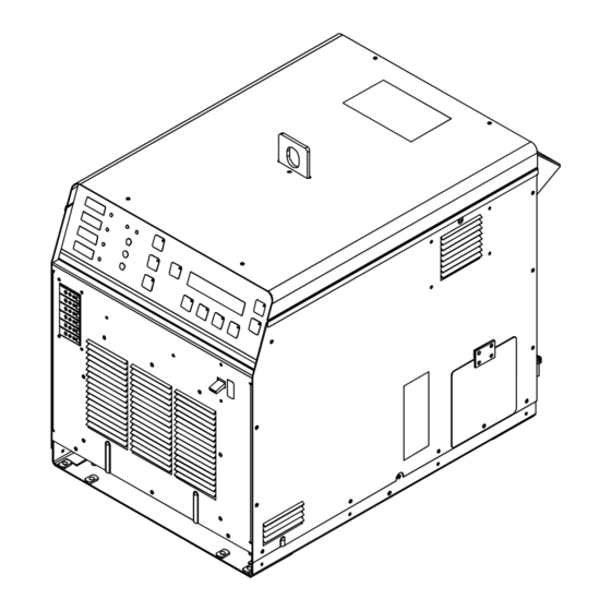
SECTION 5 − COMPONENTS AND CONTROLS 5-1. Controls 803 995-B LED lights to indicate a system limit condi- 14 Parameter Button When a control panel button is pushed tion. the yellow lamp lights to indicate ac- Use button to display real time power Heat On LED tivation. -
Page 30: Section 6 − Setup And Operation
SECTION 6 − SETUP AND OPERATION 6-1. Safety Equipment Wear following during operation: Dry, Insulating Gloves Safety Glasses With Side Shields DO NOT wear rings or watches during operation. sb3.1* 1/94 6-2. System Description The ProHeat 35 Induction Heating Power Source is designed to function either as an air-cooled system or a liquid- cooled system. - Page 31 Possible selections: Degree Units: °F / °C Tolerance: ±5 to 99 in °F (±3 to 55 in °C) Backlight: Yes / No Input Type: K TC Control Mode: Temp / Time / Manual Power Output: 1 to 35 System Lock: Yes / No Degree Units −...
-
Page 32: Programming
NOTE All parameters in System Setup are considered global, and any changes to the system set-up parameters will apply to all programs. To reset the system back to factory default settings, turn off the power source, and wait until the display goes blank. Turn on the power source. -
Page 33: Bake-Out
NOTE The minimum and maximum temperature settings for preheat are 0 and 10005 F (−18 and 5385 C). The minimum and maximum soak times are 0 and 1000 hours. When the system is utilizing air-cooled blankets, the maximum temperature setting is 4005 F (2045 C). If the program setting is above 4005 F (2045 C), the following screen will appear on the LCD display when the Run button is pressed: Maximum Temperature Message Screen Cannot enter Run mode... -
Page 34: Pwht (Post-Weld Heat Treat)
Maximum Temperature Message Screen Cannot enter Run mode Programmed temperature settings exceed air cooled limits (400 _F, 204 _C) 6-4-1-3. PWHT (Post-Weld Heat Treat) The post-weld heat treat process allows the operator to program a post-weld heat treat where ramp temperature (on increase and decrease) and ramp rates are the same. -
Page 35: Custom Program
NOTE The minimum and maximum ramp temperature settings for PWHT are 0 and 14505 F (−18 and 7885 C). The minimum and maximum ramp rates are 10 and 99995 F/hr (6 and 55555 C/hr). The minimum and maximum soak temperatures are 0 and 14505 F (−18 and 788 5 C). - Page 36 Ramp increases or decreases the temperature in the part at a controlled rate in degrees per hour. A maximum temperature of 1450° F (788° C) and a maximum rate of 9999° F/hr (5555° C/hr) can be programmed. Soak will hold the temperature for a programmed time. A maximum hold (soak) time of 99:59 (hours:minutes) can be programmed.
- Page 37 Soak Function When type is set to Soak, the following screen appears on the display: Custom Program Screen Mode..: Custom Program Segment..: Type..:>Soak Soak Time..: 00:01:00 Use the Cursor button to move the cursor to the Soak Time position and use the Increase or De- crease button to set the desired value.
- Page 38 Typical 5-Segment Custom Program Custom Program Screen Mode..: Custom Program Segment..: Type..:>Step Temperature: Temperature increases to 600 degrees at full-programmed power. Custom Program Screen Mode..: Custom Program Segment..: Type..: Ramp 600 _/Hr Temperature:>1250 Ramp Rate: Controlled heating to 1250 degrees F at a ramp of 600 degrees per hour. Custom Program Screen Mode..: Custom Program Segment..:...
-
Page 39: Manual Control
6-4-2. Manual Control Manual control allows programming of a specific power level for a specific period of time. When this process is se- lected, the following screen appears on the display: Manual Program Screen Mode..: Manual Power..: 0.0 KW Command.: 0.0 KW Current: Run Time: 00:03:00... -
Page 40: Custom Program
6-5-1-2. Custom Program Run Status Screen Mode..: Custom Program TC5: Target Temp: −−−− TC6: Countdown..: −−:−−:−− Segment: Status..: Stopped During active operation, Target Temp shows the target temperature based on the active segment, Countdown shows the time remaining in a soak segment, and Status shows the program segment type (step, soak, ramp, hold, or stopped) of the active segment and the active segment number. -
Page 41: Real-Time Operation
Firmware Revision X.XX Copyright (c) 2005 Miller Electric Mfg. Co. X.XX indicates the firmware revision number installed in the unit. If an error is detected during the check routine, the system fault LED illuminates and an error message screen appears on the display (see Section 9-5). - Page 42 The display defaults to the Run Status screen from the last program used and the Run Status button indicator LED illuminates. If no fault or limit conditions are present, system status lights are not illuminated. Once set up is complete for the desired program procedure (see Section 6-3), pressing the Run button will initiate a heating cycle.
- Page 43 To make changes to a program while in run mode, press the Hold button and the yellow indicator LED will illuminate, and the Run button yellow indicator LED will turn off. When in hold, the system will maintain the actual temperature of the hottest thermocouple while the program is being changed. Press the Program button and the yellow indicator LED will illuminate.
-
Page 44: System Operating Characteristics
6-9. System Operating Characteristics The power source delivers a high-frequency alternating current output that energizes the coil creating the magnetic field used to heat the workpiece. The power source output characteristics are a function of the configuration, type and number of coils used as shown in the following table: Table 6-1. -
Page 45: Section 7 − Maintenance
SECTION 7 − MAINTENANCE 7-1. Routine Maintenance Y Disconnect power Maintain more often before maintaining. during severe conditions. 3 Months Replace Clean Output Clean Ground Damaged Or Connector Sense Lead Unreadable Contacts Receptacles Labels Repair Or Replace Cracked Cables And Cords Check Integrity Of Clean Operator Protective Plug,... -
Page 46: Section 8 − Safety Precautions For Servicing
SECTION 8 − SAFETY PRECAUTIONS FOR SERVICING 8-1. Symbol Usage safety_ihom 8/03 Means Warning! Watch Out! There are possible hazards with this procedure! The possible hazards are shown in the adjoining symbols. Y Marks a special safety message. This group of symbols means Warning! Watch Out! possible ELECTRIC SHOCK, MOVING PARTS, and HOT PARTS hazards. -
Page 47: Additional Symbols For Installation, Operation, And Maintenance
8-3. Additional Symbols for Installation, Operation, and Maintenance FALLING UNIT can cause injury. OVERUSE can cause OVERHEATING D Use handle and have person of adequate D Allow cooling period. physical strength lift unit. D Reduce output or reduce duty cycle before D Move unit with hand cart or similar device. -
Page 48: Section 9 − Diagnostics & Troubleshooting
SECTION 9 − DIAGNOSTICS & TROUBLESHOOTING The ProHeat 35 power source has on-board capabilities to aid in troubleshooting problems should any conditions occur during operation. This troubleshooting capability consists of the Fault LED, Limit LED, and message screens that appear on the front panel LCD display. 9-1. -
Page 49: Limit Conditions
9-2. Limit Conditions A limit condition indicates that the system has encountered an open thermocouple or is outside the range of its optimum operating conditions or parameters. Should a limit condition occur during operation, the yellow Limit LED will flash to indicate a problem. If the active screen on the LCD display is Run Status or Parameters, a message describing the particular limit condition will appear on the display. -
Page 50: Fault Conditions
Limit Condition Additional Information L07: Output Voltage Limit Tighten blanket against pipe surface L08: Output Voltage Limit Increase number of turns Increase coil space Shorten extension cable Increase insulation width L09: Output Current Limit Tighten blanket against pipe surface L10: Output Current Limit Increase number of turns Decrease coil space Tighten cable on insulation... -
Page 51: System Diagnostic Screens
Fault Condition Additional Information F59: Output Current Fault Service required F60: Temperature Sensor Fault Check control TC connections Check control TC extension cable F61: Coolant Flow Fault Check for coolant leak Clean for coolant blockage Check coolant filter and level Check coolant connections F62: Isolation Fault Check for exposed conductor... - Page 52 System Diagnostic Screen RemCmd: 1023 Off Cable1: LQD DIAG1 OutI1: Cable2: LQD OutI2: ClntFR: 0.75 GPM IsrcFb: ClrSts: Flowing RemCmd − This is the value of the remote command and the status of the remote contactor. NOTE Remote controls can be used to enable/disable output. They do not affect output power level.
- Page 53 VLnA-B − This is the phase to phase line voltage between phases A and B. VLnB-C − This is the phase to phase line voltage between phases B and C. VLnC-A − This is the phase to phase line voltage between phases C and A. VBus −...
-
Page 54: Removing Wrapper And Measuring Input Capacitor Voltage
9-7. Removing Wrapper and Measuring Input Capacitor Voltage Y Turn Off welding power Y 900 Volts dc can be present on the capacitor bus and source, disconnect significant DC voltage can remain on capacitors input power. after unit is Off. Always check the voltage on Y Significant DC voltage can inverter assembly as shown to be sure the input Tools Needed:... - Page 55 Notes MATERIAL THICKNESS REFERENCE CHART 24 Gauge (.025 in) 22 Gauge (.031 in) 20 Gauge (.037 in) 18 Gauge (.050 in) 16 Gauge (.063 in) 14 Gauge (.078 in) 1/8 in (.125 in) 3/16 in (.188 in) 1/4 in (.25 in) 5/16 in (.313 in) 3/8 in (.375 in) 1/2 in (.5 in)
-
Page 56: Section 10 − Electrical Diagram
SECTION 10 − ELECTRICAL DIAGRAM Figure 10-1. Circuit Diagram OM-222 166 Page 50... - Page 57 218 057-F OM-222 166 Page 51...
-
Page 58: Section 11 − Parts List
SECTION 11 − PARTS LIST Hardware is common and not available unless listed. See Figure 11-3 See Figure 11-2 804 218-C Figure 11-1. Wrappers Item Dia. Part Mkgs. Description Quantity Figure 11-1. Wrappers ....+217 470 PANEL, side RH . - Page 59 Hardware is common and not available unless listed. 804 219-A Figure 11-2. Front Panel Item Dia. Part Mkgs. Description Quantity Figure 11-2. Front Panel ....217 323 PANEL, front .
- Page 60 Hardware is common and not available unless listed. 804 220-A Figure 11-3. Rear Panel Item Dia. Part Mkgs. Description Quantity Figure 11-3. Rear Panel ....217 324 PANEL, rear .
- Page 61 Hardware is common and not available unless listed. 804 221-D Figure 11-4. Base w/Components Item Dia. Part Mkgs. Description Quantity Figure 11-4. Base w/Components ....217 328 FRAME, lifting .
- Page 62 Hardware is common and not available unless listed. Figure 11-6 804 222-A Figure 11-5. Top Windtunnel Item Dia. Part Mkgs. Description Quantity Figure 11-5. Top Windtunnel ....218 424 WINDTUNNEL, top .
- Page 63 Hardware is common and not available unless listed. 804 223-A Figure 11-6. Capacitor Assembly Item Dia. Part Mkgs. Description Quantity Figure 11-6. Capacitor Assembly . . . C3-C6 ..218 685 CAPACITOR, popyp met film 1.5 uf 700 VAC .
- Page 64 Hardware is common and not available unless listed. 804 224-C Figure 11-7. Right Windtunnel Item Dia. Part Mkgs. Description Quantity Figure 11-7. Right Windtunnel ....216 630 WINDTUNNEL, RH .
- Page 65 Hardware is common and not available unless listed. 804 431-C Figure 11-8. Right Windtunnel (400 V Model Only) Item Dia. Part Mkgs. Description Quantity Figure 11-8. Right Windtunnel (400 V Model Only) ....216 630 WINDTUNNEL, RH .
- Page 66 Hardware is common and not available unless listed. 804 225-A Figure 11-9. Left Windtunnel Item Dia. Part Mkgs. Description Quantity Figure 11-9. Left Windtunnel ....216 631 WINDTUNNEL, LH .
- Page 67 Item Dia. Part Mkgs. Description Quantity Figure 11-9. Left Windtunnel (Continued) ..PLG16, 121,122 . . . 131 054 HOUSING RCPT+SKTS,(SERVICE KIT) ......
- Page 68 Hardware is common and not available unless listed. 804 300-A Figure 11-10. Hermaphroditic Blank Plug Assy Item Dia. Part Mkgs. Description Quantity Figure 11-10. Hermaphroditic Blank Plug Assy ....221 440 O-RING, .737 ID x .103 CS .
- Page 69 Notes...
- Page 70 Notes...
- Page 71 Effective January 1, 2006 (Equipment with a serial number preface of “LG” or newer) This limited warranty supersedes all previous Miller warranties and is exclusive with no other Warranty Questions? guarantees or warranties expressed or implied. LIMITED WARRANTY − Subject to the terms and conditions...
- Page 72 Contact the Delivering Carrier to: File a claim for loss or damage during shipment. For assistance in filing or settling claims, contact your distributor and/or equipment manufacturer’s Transportation Department. © PRINTED IN USA 2006 Miller Electric Mfg. Co. 2006−01...
Need help?
Do you have a question about the ProHeat 35 OM-222 166F and is the answer not in the manual?
Questions and answers