Advertisement
Table of Contents
- 1 General Information
- 2 General Safety Rules
- 3 Technical Features
- 4 Accessory Equipment
- 5 Ordering Spares
- 6 Installation Instructions
- 7 Moving and Transporting
- 8 Connecting to the Power Supply
- 9 Electrical Scheme
- 10 Lighting the Stove for the First Time
- 11 Room Temperature Setting
- 12 The Remote Control
- 13 Sparking Plug
- 14 Guarantee Conditions
- Download this manual
Advertisement
Table of Contents

Summary of Contents for Karmek ELENA
- Page 1 PELLET STOVES ELENA MONICA LISA OPERATING AND MAINTENANCE HANDBOOK...
- Page 2 Karmek S.R.L. PLEASE NOTE: Karmek reserves itself to carry out unsubstantial changes to the stove’s components, which may not be reported in the present handbook, those being of small entity. Occasional appearance changes from the flyers are due to ordinary seasonal updates.
- Page 3 A. GENERAL INFORMATION a.1 General safety rules a.2 Technical features a.3 Accessory equipment a.4 Identity plate a.5 Guarantee a.6 Suitable fuel a.7 Ordering spares a.8 Waste material B. INSTALLATION INSTRUCTIONS b.1 Initial warnings b.2 Moving and transporting b.3 Positioning b.4 Installing the flue gas outlet b.5 Installing the combustion air inlet pipe b.6 Connecting to the power supply C.
- Page 4 d.7 Room probe d.8 Sparking plug d.9 Thermocouple E. ORDINARY CLEANING AND MAINTENANCE e.1 Cleaning and maintenance by the customer e.2 Periodic maintenance by the Assistance Center F. ALARMS DISPLAYING f.1 Fumes temperature probe alarm f.2 Unsuccessful lighting alarm f.3 Switching-off while working alarm f.4 Power failure alarm f.5 Room thermocouple alarm G.
-
Page 5: General Information
A. GENERAL INFORMATION a.1 General safety rules ATTENTION PLEASE!!! You can never be too cautious: before the installation read and comply with these fundamental Rules: All local regulations, including those referring to national and European laws, must be respected while installing the stove. ... - Page 6 If anomalies in the functioning should occur, light the stove again only after fixing the problem at its origin. Karmek Srl is not responsible for inconveniences, tampering, breakages or any other damage due to non-observance of the instructions reported in this handbook.
-
Page 7: Technical Features
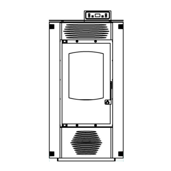
193°C - max 217°C Pellet consumption (Kg/h): 2 Kg/h Digital control display: Weekly program: Room thermostat: Manual – automatic functioning: Adjustable feet: Dimensions (mm): Elena top majolica/Elena majolica 540x490x1010 Elena steel 520x490x1010 Weight: Elena steel 100Kg Elena top majolica 109Kg Elena majolica... - Page 8 PELLET STOVE “LISA” Nominal power: Efficiency: Power supply: 230V 50Hz Power absorption: 90-230W Pellet tank capacity: 15Kg Pellet consumption (Kg/h): 1,6Kg/h CO (measured at 13% of oxygen at nominal thermal power) 0,01% Exhausted gas temperature at nominal thermal power: medium 187°C - max 214°C Digital control display: Weekly program: Room thermostat:...
-
Page 12: Accessory Equipment
The guarantee certificate, which we consigned to you when you purchased the stove, must be sent to the producer firm Karmek Srl, 8 days after delivery date the latest; otherwise, the guarantee itself will no longer be valid. The estimated 24-months guarantee is valid exclusively when the installation and test are performed by an authorized Karmek assistance center. -
Page 13: Ordering Spares
Should you use different pellets from the ones recommended the stove’s guarantee would expire. a.7 Ordering spares Exclusively authorized Karmek technical personnel must perform interventions of any entity. Please refer to the authorized assistance center or to your retailer for possible requests of spares. -
Page 14: Installation Instructions
B. INSTALLATION INSTRUCTIONS b.1 Initial warnings The device must be installed on a pavement that presents an adequate burden capacity. If the existing building does not satisfy this requirement, appropriate measures (for instance a burden distribution plate) must be taken. The installation of the device must guarantee an easy access to clean the stove, the exhausted gas piping and the flue. - Page 15 The information reported above is purely indicative for a correct installation; Karmek Srl is not responsible for what concerns the installation.
-
Page 17: Connecting To The Power Supply
b.5 Installing the combustion air inlet pipe For any described solution, two alternatives are possible: Draw the air directly from the outside through a piping (internal Ø 50mm; max length 1,5m), ● connected to the air inlet pipe on the back of the stove. Draw the air directly from the installation room, given that in the proximity of the stove an air ●... -
Page 18: Electrical Scheme
ELECTRICAL SCHEME... - Page 19 C. OPERATING INSTRUCTIONS c.1 Initial warnings All regulations, included those referring to national and European laws, must be respected when installing the device. Do not use the device as an incinerator or in any other way than that for which it was designed. Do not use any fuel other than pellets.
- Page 20 c.3 Display In the following scheme, we report the various functions of the display. IMPORTANT: If the temperature is not set within a few seconds, the display will automatically return to the previous screenshot.
-
Page 21: Lighting The Stove For The First Time
c.4 Lighting the stove for the first time A skilled technician must perform the first lighting; otherwise, the guarantee will expire. c.5 Activating the stove When the pellet tank is filled for the first time, you must remember that the screw tube, which feeds the grate, is completely empty;... -
Page 22: The Remote Control
c.7 Switching off the stove You can switch the stove off by pushing the key n. 4 for a few seconds. The message “OFF” will appear on the display; the pellet flow is interrupted and the speed of the smoke intake motor will increase to lower the temperature. - Page 23 c.9 Managing the automatic lighting (chronothermostat) The automatic lighting function permits to weekly program the lighting and switching off of the stove. Through this function, it is possible to set two daily lightings; it is also possible to avoid extra programming, by memorizing the set data.
- Page 24 UT08/UT09: they indicate the starting and stopping time of the Program 2, if the UT01 setting is set on the weekly mode (different from OFF) UT10: it modifies the weekdays you wish the Program 2 to be on. By pressing the “2” key you run over the days, and by pressing the “1”...
- Page 25 Lisa’s Elena’s Monica’s A9 Settings Description value values values Pr 01 Maximum time for the lighting (in minutes) 15’ 15’ 15’ Pr 02 Time for the stabilization of the flame during the starting phase “FIRE ON” (in 06’ 06’ 06’...
- Page 26 D. FUNCTIONS OF THE MECHANICAL AND ELECTRIC COMPONENTS d.1 Screw motor The screw motor drives the screw, which brings the pellets from the tank to the grate. d.2 Smoke intake motor The smoke intake motor is fixed on the extraction turbine on the back of the stove. Its function is to intake and to expel the fumes that form in the combustion chamber.
-
Page 27: Sparking Plug
d.6 Fumes probe fumes probe surveys fumes’ temperature in the intake turbine, and it operates when the temperature reaches 270°C, driving the stove to the conservation mode “RIS” d.7 Room probe The room probe is positioned on the back of the stove and it surveys the temperature of the room where the stove is located. - Page 28 E. ORDINARY CLEANING AND MAINTENANCE e.1 Cleaning and maintenance by the costumer Before lighting the stove, it is advisable to clean the inside of the stove. Open the door and vacuum the fire table. ● Remove the great, verify its cleanliness and clean the holes if necessary. ●...
- Page 29 F. ALARMS DISPLAYING The alarms are displayed on the command panel; on the first line the message ALAR appears, while on the second line the typology of the anomaly is displayed. The occurring of an alarm provokes the immediate stop of the stove, and only after solving the problem it is possible to restart the stove, following the instructions already reported on this handbook.
- Page 30 G. SOLUTION TO POSSIBLE PROBLEMS PROBLEM POSSIBLE CAUSE SOLUTIONS The display is blank and Lack of power. Check if the power supply cable is the keys do not work. connected. Anomalies in the connection between the display and the Check if the display and the card are card.
- Page 31 PROBLEM POSSIBLE CAUSE SOLUTIONS The stove is blocked for Technical problem with the IMPORTANT: unplug stove an unsuccessful pellet screw. before supply. ridding the screw of possible obstructions ridding the chute of possible obstructions removing pellet dust accumulation from the bottom of the tank.
-
Page 32: Guarantee Conditions
GUARANTEE CONDITIONS: AT THE END OF EACH SEASON, IT IS OBLIGATORY TO HAVE THE AUTHORIZED ASSISTANCE CENTER PERFORM A GENERAL CLEANING OF THE MODULE; OTHERWISE, THE GUARANTEE WILL EXPIRE.
Need help?
Do you have a question about the ELENA and is the answer not in the manual?
Questions and answers