
Related Manuals for Sony DXF-C50WA


Summary of Contents for Sony DXF-C50WA
- Page 1 4-290-200-01 (2) Electronic Viewfinder Operating Instructions_____ DXF-C50WA © 2011 Sony Corporation...
- Page 4 • • • • • • •...
- Page 5 • •...
- Page 10 • • •...
- Page 11 UPPER RIGHT LOWER LEFT UPPER RIGHT LOWER LEFT • • •...
- Page 12 UPPER RIGHT LOWER LEFT...
- Page 13 • • • • • • •...
- Page 14 • • M E N U M E N U F U N C T I O N A S S I G N M O N O A S S I G N . M A G M E N U M A G N I F I C A T I O N M O N C H R O M E...
- Page 16 • • [MONO] [MAG] [OFF] [OFF] [MODE1] [ON] [ON]...
- Page 17 [STD] [COLOR] [CNT] [OFF] [OFF] [MODE1] [CNT] [RIGHT] [AUTO]...
- Page 18 [OFF] [3X3] • • [OFF] [RIGHT] [OFF] [LINE] [OFF] [50] [50]...
- Page 19 [OFF] [ON] [ON] [ON] [ON] [ON] [ON] [ON] [OFF]...
- Page 20 [AUTO] [AUTO] [EXEC] [AUTO]...
- Page 21 • •...
- Page 24 The model and serial numbers are located at the bottom. Record these numbers in the spaces provided below. Pour les clients en Europe Refer to these numbers whenever you call upon your Sony Ce produit portant la marque CE est conforme à la dealer regarding this product.
- Page 25 Für Kunden in Europa Der Hersteller dieses Produkts ist Sony Corporation, 1-7-1 Konan, Minato-ku, Tokyo, Japan. Der autorisierte Repräsentant für EMV und Produktsicherheit ist Sony Deutschland GmbH, Hedelfinger Strasse 61, 70327 Stuttgart, Deutschland. Bei jeglichen Angelegenheiten in Bezug auf Kundendienst oder Garantie wenden Sie sich bitte an die in den separaten Kundendienst- oder Garantiedokumenten aufgeführten...
-
Page 26: Table Of Contents
Table of Contents Precautions Precautions..........26 • The LCD panel fitted to this unit is manufactured with high precision technology, giving a functioning pixel Overview ..........27 ratio of at least 99.99%. Thus a very small proportion of Functions of Parts and Controls.... 28 pixels may be “stuck”, either always off (black), always Attaching to the Camera...... -
Page 27: Overview
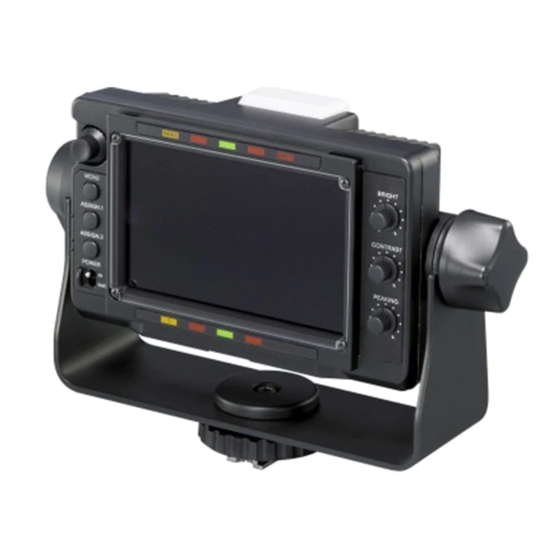
The studio monitor hood is supplied. The VFH-570 optional OB hood offers superior shading The DXF-C50WA Electronic Viewfinder is a 5-type character. LCD color viewfinder for use with a Sony color video camera/camcorder. This viewfinder has the following features: Wide viewing angle 5-type IPS-LCD enables wide viewing angle. -
Page 28: Functions Of Parts And Controls
Functions of Parts and Controls a MAG (magnification) indicator The lamp lights in the same way as the R TALLY indicator lights when a red tally signal is input. To enable Lights up when the displayed image is magnified (when up-tally lamp, set the ASSIGN. -
Page 29: Attaching To The Camera
(attention) indicator (amber) Attaching to the Camera This indicator lights up when the shutter switch of the camera is set to ON, or gain is over 3 dB. Certain models allow you to specify the operating Slide the bracket fully into the accessory shoe of the conditions under which the indicator lights up. -
Page 30: Turning On The Viewfinder
Turning on the Adjusting the Viewfinder Viewfinder Position When the camera is turned on and the POWER switch of Use the unit after adjusting the viewfinder position as the viewfinder is set to ON, power is supplied to the follows: viewfinder. -
Page 31: Tilt Adjustment
Tilt Adjustment Attaching Accessories Attaching a Hood 90° Tilt lock knob. You can attach the VFH-570 in the same way as the (Lock into supplied studio monitor hood. position by turning to the This section describes the procedure of attaching the right) studio monitor hood. -
Page 32: Attaching A Number Plate
Attaching a Number Plate Using the Focus Assist Insert the tabs on the sides of the number plate into each Function slit in the up-tally lamp. For details on menu operations, see “Using the Menu” Up-tally lamp on page 36. Slit PEAKING PLUS Function This function can be used to sharpen the edges of an... - Page 33 Turn the control clockwise to make the edges – direction: sharper. Narrows the effective range To specify both color and area + direction: Widens the effective range Press the ASSIGN. switch that is assigned the PEAKING PLUS function to switch to the PEAKING PLUS mode.
-
Page 34: Magnification Function
The edges of the object that coincides with the color MODE1: Standard magnified display detected in step 4 are sharpened within the area selected in step 3. Turn the control clockwise to make the edges sharper. To enhance the edges of the entire image Press the ASSIGN. -
Page 35: Using The Level Adjust Function
Select “YES.” Using the Level Adjust The setting is executed. Select “NO” to cancel. “COMPLETE” is displayed when setting is finished. Function “ERROR” is displayed if a setting is not finished completely. In this case, input the color bar correctly from step 3. -
Page 36: Using The Menu
item select mode. Press the MENU switch again to Using the Menu return to page select mode. Select menu items. Many of the viewfinder’s functions can be set by a menu With the mark positioned to the left of a menu item operation. - Page 37 The setting is entered and the menu returns to item select mode. If you press the MENU switch before pressing the MENU SEL control, the setting returns to the value that was previously set and then the menu returns to item select mode.
-
Page 38: List Of Menu Items
List of Menu Items • “– – –” appears to the left of settings that cannot be Notes selected. • Some settings cannot be selected unless the previous menu item is set to “ON.” Page Menu Item Settings Function (default in [ FUNCTION ASSIGN. - Page 39 Page Menu Item Settings Function (default in [ PEAKING MODE [STD]/PLUS PEAKING For selecting a peaking mode. STD: Standard mode PLUS: PEAKING PLUS mode COLOR/AREA [COLOR]/AREA/ For selecting a peaking plus mode. BOTH COLOR: Sharpens the edges for the selected color only AREA: Sharpens the edges for the selected area only BOTH: Sharpens the edges for the selected color and area only...
- Page 40 Page Menu Item Settings Function (default in [ MAGNIFICATION [OFF]/ON MAGNIFICATION For selecting normal display (OFF) or magnified display (ON). Normal display (OFF) is selected whenever the power is turned on. [MODE1]/MODE2/ MODE SEL For selecting a magnification mode. MODE3 [CNT]/UPPER/ MAG POSITION For selecting the area to magnify when the magnification...
- Page 41 Page Menu Item Settings Function (default in [ WAVEFORM Displays a simplified input signal waveform as a sub display. The right illustration is an example of the waveform monitor when a color bar Selected signal is input. LINE Notes • Adjust the output level of camera under the LEVEL ADJUST menu before using the WAVEFORM menu Cursor...
- Page 42 Page Menu Item Settings Function (default in [ [OFF]/ON PRESET PRESET For selecting whether to enable the settings of the BRIGHT, CONTRAST, PEAKING controls and the chroma level in the FUNCTION menu, or to enable the preset “PRST BRIGHT,” “PRST CONTRAST,” “PRST PEAKING,” and “PRST CHROMA”...
- Page 43 Page Menu Item Settings Function (default in [ AUTO ADJUST For SD signal input LEVEL ADJUST [AUTO]/PRST 1/ For adjusting the output level of the camera automatically PRST 2/PRST 3 (AUTO). Otherwise, for selecting a preset’s adjustable value manually (PRST 1/PRST 2/PRST 3). Normally selecting “AUTO”...
-
Page 44: Error Message
Error Message Specifications General Display Description Power supply 10.5 V to 17.0 V DC (supplied by the ERROR Failure in “COLOR DETECT” in camera) PEAKING PLUS mode, or “AUTO Power consumption ADJUST” in LEVEL ADJUST menu 7.8 W BACKUP ERROR Checksums of the EEPROM backup Operating temperature data are not consistent... - Page 45 1080 * 23.98PsF 26.97 47.95 Note Always verify that the unit is operating properly before 24PsF use. SONY WILL NOT BE LIABLE FOR DAMAGES 25PsF 28.13 OF ANY KIND INCLUDING, BUT NOT LIMITED 29.97PsF 33.72 59.94 TO, COMPENSATION OR REIMBURSEMENT ON 30PsF 33.75...
- Page 48 Sony Corporation Printed in Japan...
Need help?
Do you have a question about the DXF-C50WA and is the answer not in the manual?
Questions and answers