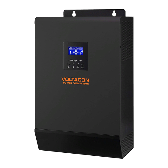
Summary of Contents for Voltacon 4KVA
-
Page 1: Parallel Operation
User Manual PARALLEL OPERATION AUTONOMOUS SOLAR INVERTER 1KVA-5KVA INVERTER / CHARGER 5 Years Manufacturer's Warranty Version: 1.2 VOLTACON UK LIMITED | 5 ARGOSY COURT WHITLEY BUSINESS PARK | CV3 4GA | COVENTRY | UNITED KINGDOM... -
Page 2: Package Contents
4KVA/5KVA Parallel Installation Guide 1. Introduction This inverter can be used in parallel with two different operation modes. 1. Parallel operation in single phase with up to 4 units. The supported maximum output power is 16KW/20KVA. 2. Three units work together to support three-phase equipment, one inverter per phase. The supported maximum output power is 12KW/15KVA. - Page 3 Step 4: Remove two screws as below chart to take out cover of parallel communication. Step 5: Install new parallel board with 2 screws tightly. Step 6: Re-connect 2-pin and 14-pin to original position. Parallel board Communication board info@voltacon.com www.voltacon.com...
-
Page 4: Mounting The Unit
Be sure the length of all battery cables is the same. Otherwise, there will be voltage WARNING: difference between inverter and battery to cause parallel inverters not working. Follow below chart to connect batteries. All battery cables are connected from inverters to batteries via the same BUS bar. info@voltacon.com www.voltacon.com... - Page 5 Recommended battery cable and terminal size: Ring Terminal Typical Battery Torque Model Wire Size Cable Dimensions Amperage capacity value D (mm) L (mm) 1*4AWG 33.2 4KVA 200AH 2~ 3 Nm 2*8AWG 29.2 1*4AWG 33.2 5KVA 200AH 2~ 3 Nm 2*8AWG 29.2 info@voltacon.com www.voltacon.com...
-
Page 6: Ac Input Connection
Support three-phase equipment Connect Line wires of the inverter to each phase of the utility. Connect Neutral wires of AC input from each unit to Neutral BUS bar. Refer to below figure for connection of AC input. Breaker info@voltacon.com www.voltacon.com... - Page 7 Suggested cable wire and breaker requirement for AC input connection: Amperage for breaker Model AWG no. Torque 40 A 4KVA 10 AWG 1.4~1.6Nm 50 A 5KVA 8 AWG 1.4~1.6Nm 7. AC Output (Load) Connection Parallel in single phase Connect Line wires of AC output from each unit to Line BUS bar.
- Page 8 BUS bar to AC output should be X pcs of cable from inverter to BUS bar and breaker. X indicates the number of inverters connected in parallel. Suggested cable and breaker requirement for AC output connection: Amperage for breaker Model AWG no. Torque 4KVA 10 AWG 1.4~1.6Nm 5KVA 8 AWG 1.4~1.6Nm 8. PV Connection Please refer to user manual of single unit for PV Connection.
-
Page 9: Parallel Cable Connection
Parallel cable includes parallel communication cable and current sharing cable. Please follow below chart to connect to the inverter. 9-1. Parallel Operation in Single phase Two inverters in parallel: Three inverters in parallel: Four inverters in parallel: 9-2. Support 3-phase equipment Follow below chart to connect inverters to support 3-phase equipment. info@voltacon.com www.voltacon.com... -
Page 10: Program Description
30, it’s necessary to have all inverters connected to PV modules and PV input is normal to allow the system to provide power to loads from solar and battery power. Otherwise, the system will provide power to loads from utility. info@voltacon.com www.voltacon.com... - Page 11 Ensure all breakers in Line wires of load side are open and each Neutral wires of each unit are connected together. Step 2: Switch on DC breakers of each unit. Step 3: Turn on each unit. LCD display in Master unit LCD display in Slave unit info@voltacon.com www.voltacon.com...
- Page 12 Otherwise, the AC icon will flash and they will not work in line mode. LCD display in L1-phase unit LCD display in L2-phase unit LCD display in L3-phase unit info@voltacon.com www.voltacon.com...
-
Page 13: Troubleshooting
Restart the inverter. AC output current unbalance If the problem remains, please contact your installer. Switch off the inverter and check LCD setting #28. AC output mode setting is different. If the problem remains, please contact your installer. info@voltacon.com www.voltacon.com... - Page 14 VOLTACON UK Limited Power Conversion & Lighting 5 Argosy Court | Whitley Business Park | Coventry | CV3 4GA | Coventry T: +44 2476559005 | www.voltacon.com | www.ledison-led-lights.co.uk info@voltacon.com...


Need help?
Do you have a question about the 4KVA and is the answer not in the manual?
Questions and answers