
Related Manuals for V-fit TRV1-12


Summary of Contents for V-fit TRV1-12
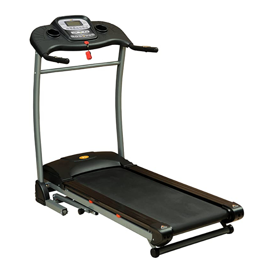
- Page 1 SERIAL NO. HY1967-UK TRV1-12 Folding Power Treadmill Assembly & User Manual Please ensure that you read this manual carefully before attempting to assemble or use your new product and retain for future use...
-
Page 2: Table Of Contents
Contents Page Section General Information ..Before you start ..Safety ..... 5 Exercise Information . -
Page 3: General Information
General Information Quality Guarantee This exercise product has been designed and This product is guaranteed for DOMESTIC USE ONLY for manufactured to comply with the latest (BS EN 957) a period of 1 YEAR from the original certified date of British and European Safety Standards. -
Page 4: Before You Start
Before you Start Tools If required, most of our products products are supplied with basic tools, which will enable youto successfully assemble your product. However, you may find it beneficial to have a soft-headed hammer and perhaps an adjustable spanner handy as this may help. Prepare the Work Area It is important that you assemble your product in a clean, clear, uncluttered area. -
Page 5: Safety
Safety Before you undertake any programme of exercise that will increase cardiovascular activity please be sure to consult with your doctor. Frequent strenuous exercise should be approved by your doctor and proper use of your product is essential. Please read this manual carefully before commencing assembly of your product or starting to exercise. - Page 6 Safety Safety-Treadmill Specific When using an electrical appliance, basic precautions should always be followed, including the following: Read all instructions before using the treadmill. DANGER – To reduce the risk of electric shock: Always unplug this appliance from the electrical outlet immediately after using and before cleaning.
-
Page 7: Exercising Information
Exercising Information Warm Up A successful exercise programme consists Beginning of three parts, Warm Up, Aerobic Exercise and Cool Down. Never start a training How you begin to exercise will vary session without warming up. Never finish from person to person. If you have one without cooling down correctly. -
Page 8: Exercise Information
Exercising Information Target Zone (con't) USERS UNCONDITIONED CONDITIONED TARGET ZONE - A TARGET ZONE - B (Years) (Beats per Minute) (Beats per Minute) 20-24 145 - 165 155 - 175 25-29 140 - 160 150 - 170 30-34 135 - 155 145 - 165 35-39 130 - 150... - Page 9 Exercising Information Shoulder Lift Rotate and lift your right shoulder up towards your ear for one count. Relax then repeat for the left shoulder. Repeat 3 - 4 times. Calf / Achilles Stretch Turn towards the wall and place both hands on it. Support yourself with one leg while the other is placed behind you with the sole flat on the floor.
-
Page 10: Assembly
Assembly Overview Drawing USING THE SAFETY KEY You will need to install the SAFETY KEY (2) in order to operate your product. This acts as an emergency STOP should you encounter any difficulties. SETTING UP THE SAFETY KEY With the product switched off, place the Safety Key (2) into the recess in the front of the Computer Console (1). - Page 11 Assembly ACCESSORY FITMENT LIST These are all the accessories you will need to comp lete the assembly of your product. The following accessories are supplied in a pack and should be checked before attempting assembly. Item 5 Item 7 Item 19 Qty 10 Qty 2 Qty 2...
- Page 12 Assembly Carefully unpack each component, checking against the parts list that you have all the necessary parts to complete the assembly of your product. Please note that some of the parts may be pre-fitted to major Beny Sports Co. UK Ltd Unit 8, Riparian Way, components, so please check carefully before contacting our The Crossings, Cross Hills,...
- Page 13 Assembly Connect the Upper Control Wire (62) in the Right Upright to the matching wire from the Console (1). Fit the Console (1) to the Uprights (4L &R) using 3 x M8 x 15mm Allen Bolts (5) and 3 x M8 Lock Washers (6) on each side. Page 13...
- Page 14 Assembly Assemble the Cross Bar (13) to the inside of the Uprights (4L & R) using 2 x M8 x 45mm Allen Bolts (7) and 2 x M8 Lock Washers (6). Page 14...
- Page 15 Assembly Attach the Upright Covers (20L & R) using 4 x M4 x 15mm Self Tapping Screws (54). Note FULLY TIGHTEN all Bolts, Nuts and Fittings now, ensuring that your product in located on a clear flat surface before doing so. Your product will now be ready to use.
-
Page 16: User Instructions
User Instructions TO FOLD YOUR TREADMILL Lift the rear of the Main Frame and fold upwards until the Locking Knob (29) locks into position. To lower the Treadmill, support the Running Deck and pull the Locking Knob (29) to disingage the Locking Knob (29) and gently lower the Running Deck to the ground. WARNING When lowering the treadmill. -
Page 17: Adjusting Running Belt Tracking
User Instructions ADJUSTING THE RUNNING BELT TRACKING If the Running Belt tends to move off central during operation, step off the belt and stop the Treadmill. Start the Treadmill in Manual Programme Mode and adjust the speed to 3mph. Take the 5mm Allen Wrench and adjust the Rear Roller Location Bolts, which are accessible through the Rear Frame Caps. If the belt is moving towards the RIGHT side of the Treadmill Running Board, turn the RIGHT Rear Roller Location Bolt 1/4 turn CLOCKWISE and let the Running Belt find its new position. -
Page 18: Programme
User Instructions 1. CONSOLE PANEL 2. FUNCTION KEY: 2.1“START” “STOP”: button, in standby mode, press the START button to start the treadmill. Press the STOP to stop the treadmill, all data will be saved. To clear all data, pull the Safety Key out. 2.2 PROGRAMME: button, in standby mode, press the "P"... -
Page 19: Programme Table
User Instructions 3.4 Countdown Calorie training mode: in standby mode, press the “MODE” button 3 times, the Calories window display will flash, the default setting displays 100CAL, press the +,- button to set the required value. The setting range: 20-990CAL. Press the “START”... -
Page 20: Heart Beat Test
User Instructions 4. HEART BEAT TEST 4.1 Place both hands on the Pulse Pads, the Speed/Pulse window will show your pulse value. 4.2 Check before exercise, feet standing on the both sides of the side rails, and both hands holding the pulse pads, wait for 20 seconds and your Heart Rate will be displayed. -
Page 21: Important Safety Instruction
User Instructions OPERATION INSTRUCTION 1. BEFORE START 1.1 Plug in the power cord to a suitable earthed outlet and turn the On/Off Switch to the ON position at the front of the machine. If the machine is not in use, please turn off the power. 1.2 Clip the safe key on to your clothes and place the Safety Key magnet into the computer. - Page 22 Assembly Page 22...
-
Page 23: Parts List
Assembly PARTS LIST PART No. DESCRIPTION M46 Front Roller ....1 Computer Console ....Motor cover . - Page 24 Beny Sports Co. UK Ltd. Unit 8, Riparian Way, The Crossings, Cross Hills, West Yorkshire BD20 7BW CUSTOMER SUPPORT is open from 9.00am to 5.00pm from Monday to Friday Tel: 01535 637711 Fax: 01535 637722 E-mail: support@benysports.co.uk Copyright BSCL 2011 Printed November / 2011...
Need help?
Do you have a question about the TRV1-12 and is the answer not in the manual?
Questions and answers