
Related Manuals for North American HVAC MOC-12HFN1-MS0W

Summary of Contents for North American HVAC MOC-12HFN1-MS0W
-
Page 1: Service Manual
NORTH AMERICAN HVAC PRODUCTS LTD Tel: 604-4308496 Fax: 1-866-9034371 www.northamericanhvac.com North American Market SUPER DC INVERTER SERIES Service Manual 2014 LISAS-B-1405 Contents... - Page 3 Contents Part 1 General Information ....................1 Part 2 Indoor Units ......................... 6 Part 3 Outdoor Units ......................60 Part 4 Installation ........................75 Part 5 Electrical Control System ..................106 ※The specifications, designs, and information in this book are subject to change without notice for product improvement.
-
Page 5: Table Of Contents
General Information Part 1 General Information 1. Model Lists ....................2 2. External Appearance ................. 3 2.1 Indoor Units ......................3 2.2 Outdoor Units ......................3 3. Nomenclature ..................... 4 4. Features ...................... 5 General Information... -
Page 6: Model Lists
Cooling and heating ● ● ● ● Console Cooling and heating ● 1.2 Outdoor Units Universal Outdoor unit Model Compressor type Compressor Brand Matched indoor units MUBU-12HRFN1-M MOC-12HFN1-MS0W Rotary GMCC MCA2U-12HRFN1-M MFAU-12HRFN1-M MOC-12HFN1-MV0W Rotary GMCC MTBU-12HRDN1-M MFAU-12HRFN1-M(B) MCA2U-12HRFN1-M(B) MOZ-12HFN1-MW0W Rotary GMCC... -
Page 7: External Appearance
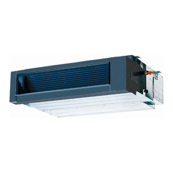
External Appearance 2. External Appearance 2.1 Indoor Units 4-way cassette (12K, 18K) 4-way cassette (24K~48K) Duct Console Ceiling-Floor (24K~48K) Ceiling-Floor (12K, 18K) 2.2 Outdoor Units Single fan outdoor unit Double fan outdoor unit General Information... -
Page 8: Nomenclature
Nomenclature 3. Nomenclature 3.1 Indoor Unit M U B T- 36 H R D N1- Q RC4 Energy Efficiency Code Power Supply Q 220~240V,1N, 50Hz R 380~420V, 3N, 50Hz N 220~230V, 1N, 60Hz D 220V~, 3N, 60Hz C 380~420V,3N,60Hz Refrigerant N1 R410A -- R22 D DC Inverter -- On-Off... -
Page 9: Features
Features Features 4.1. Low ambient kit is standard for outdoor units 4.2. Network control function is standard for the indoor units. 4.3. Standard auto restart function and follow me function. 4.4. Slim cassette with standard remote controller, wire controller and CCM for optional. Med Duct and HESP duct with standard wired controller, remote controller and CCM for optional. -
Page 10: Part 2 Indoor Units
Indoor Units Part 2 Indoor Units 4-way Cassette Type ............7 Duct Type ................. 22 Ceiling & Floor Type ............38 Console Type ..............50 Indoor Units... -
Page 11: Way Cassette Type
4-way Cassette Type 4-way Cassette Type 1. Features (12K, 18K) ............8 2. Features (24K,36K) ............9 3. Dimensions ..............13 4. Service Space ..............15 5. Wiring Diagrams ............. 16 6. Electric Characteristics ..........18 ... -
Page 12: Features (12K, 18K)
Features (12K, 18K) 1. Features (12K, 18K) 1.1 New panel 360°surrounding air outlet design, affords comfortable feeling 1.2 Compact design The body size is 570×260×570mm, it’s just smaller than the ceiling board, so it’s very easy for installation and will not damage the decoration. The panel size is 647×50×647mm. ... -
Page 13: Features (24K,36K)
Features (24K,36K) Features (24K,36K 2.1 Overview Compact design, super slim body size, less space requiring in installation Each louver can be separately controlled, more comfort air blowing is possible. Auto-lifting panel design, more convenient to clean and maintain the filter.(optional) Old Cassette New slim cassette Volume change... - Page 14 Features (24K,36K) New air-intake 2.3 Optional ionizer generator Ionizer generator is optional to get refreshing air to your room. Ionizer can be switched on or off by remote controller. When pressing the Clean Air button on the remote controller, Ionizer will work and the indicator light on display board will shine.
- Page 15 Features (24K,36K) 2.4 External air duct design Reserve external air duct, more flexible for the air supply. 2.5 Built-in draining pump Due to the improvement of structure, more convenient to repair or replace the draining pump. Draining Pump Built-in draining pump to make sure condensed water drain out reliably.
- Page 16 Features (24K,36K) Terminals for alarm lamp and long-distance on-off controller connection are standard Reserve terminals for the connection of alarm lamp and long-distance on-off controller, more human control. Alarm lamp Long-distance on-off controller 2.7 Optional touch screen wired controller ...
-
Page 17: Dimensions
Dimensions 3. Dimensions 12K, 18K Drain hole Gas side ( for Service ) Liquid side Body 4-install hanger 150 Distribution duct E-parts box 4-Screw hole (for install panel) Drain pipe Fresh air intake Wiring connection port Panel Indoor Units... - Page 18 Dimensions 24K,36K,48K 92 92 Fresh air intake 4-install hanger Body Gas side Liquid side Wiring connection port E-parts box Service hole for Test mouth & Test cover draining pump Drain hole 92 92 92 92 Panel Unit: mm Capacity(KBtu/h) Indoor Units...
-
Page 19: Service Space
Service Space 4. Service Space Indoor Units... -
Page 20: Wiring Diagrams
Wiring Diagrams 5. Wiring Diagrams MCA2U-12HRFN1-M MCA2U-18HRFN1-M MCA2U-12HRFN1-M(B) Indoor Units... - Page 21 Wiring Diagrams MCD-24HRFN1-M MCD-36HRFN1-M MCD-48HRFN1-M MCD-24HRFN1-MW Indoor Units...
-
Page 22: Electric Characteristics
Electric Characteristics Electric Characteristics Indoor Unit Model Voltage MCA2U-12HRFN1-M 208-230V 187V 253V MCA2U-12HRFN1-M(B) 208-230V 187V 253V MCA2U-18HRFN1-M 208-230V 187V 253V MCD-24HRFN1-M 208-230V 187V 253V MCD-24HRFN1-MW 208-230V 187V 253V MCD-36HRFN1-M 208-230V 187V 253V MCD-48HRFN1-M 208-230V 187V 253V Sound Levels 1.4m Microphone Noise level dB(A) Model MCA2U-12HRFN1-M... -
Page 23: Accessories
Accessories Accessories Name Shape Quantity 1. Expansible hook Installation fittings 2. Installation hook 3. Installation paper board 4. Out-let pipe sheath 5. Out-let pipe clasp Drainpipe Fittings 6. Tightening band 7. Drain joint 8. Remote controller Remote controller & Its 9. -
Page 24: The Specification Of Power
The Specification of Power 9. The Specification of Power MCA2U-12HRFN1-M Model MCA2U-12HRFN1-M(B) MCD-24HRFN1-MW MCA2U-18HRFN1-M Phase 1-phase 1-phase Power Frequency and Voltage 208-230V, 60Hz 208-230V, 60Hz Circuit Breaker/ Fuse (A) 20/16 40/30 Indoor Unit Power Wiring (mm Ground Wiring Outdoor Unit Power Wiring 3×2.0 3×2.0 Indoor/Outdoor... -
Page 25: Field Wiring
Field Wiring 10. Field Wiring MCA2U-12HRFN1-M, MCA2U-12HRFN1-M(B), MCA2U-18HRFN1-M, MCD-24HRFN1-MW MCD-24HRFN1-M, MCD-36HRFN1-M, MCD-48HRFN1-M Indoor Units... -
Page 26: Duct Type
Duct Type Duct Type 1. Features ..............23 2. Dimensions ............. 26 3. Service Space ............27 4. Wiring Diagrams ............ 28 5. Static Pressure ............31 6. Electric Characteristics ......... 33 7. Sound Level ............34 ... -
Page 27: Features
Features Features 1.1 Installation accessories: (Optional) Front Board, Canvas Air Passage, Filter, Panel, for easy installation Panel 1.2 Easy Installation: Two air inlet styles (Bottom side or Rear side) Air inlet from rear is standard for all capacity; air inlet from bottom is optional. ... - Page 28 Features Replace the motor or centrifugal fan Remove the ventilated panel firstly. Remove a half of blower housing and take out the motor with centrifugal fan. Directly remove two bolts, and then replace the motor or centrifugal fan easily. Motor Blower Housing Ventilated Panel...
- Page 29 Features 1.7 Built-in display board The standard indoor unit can be controlled by wired controller. There is a display board with a receiver in the E-box. Move out the display, and fix it in other place, even in the distance of 10m. The unit will realized remoter control. ...
-
Page 30: Dimensions
Dimensions Dimensions air inlet from rear side Air filter ( optional ) 4-install hanger Liquid side Gas side 25 Drain pipe 25 Drain pipe Test mouth & Test cover 25 Drain connecting pipe ( for pump ) Fresh air intake Electric control box Air filter ( optional ) air inlet from bottom side... -
Page 31: Service Space
Service Space Service Space Ensure enough space required for installation and maintenance. All the indoor units reserve the hole to joint the fresh air pipe. The hole size as following: Indoor Units... -
Page 32: Wiring Diagrams
Wiring Diagrams Wiring Diagrams MTBU-12HRDN1-M MTBU-18HRDN1-M MTBU-12HRDN1-M(B) Indoor Units... - Page 33 Wiring Diagrams MTB-24HRFN1-MW Indoor Units...
- Page 34 Wiring Diagrams MTB-24HRFN1-M MTB-36HWFN1-M MTB-48HWFN1-M Indoor Units...
-
Page 35: Static Pressure
Static Pressure Static Pressure 12,000Btu/h 18,000Btu/h Super high speed High speed Super high speed Mid speed High speed Mid speed Low speed Low speed 600 700 800 900 1000 1100 1200 Air volume(m /h) Air volume(m /h) 24,000Btu/h 36,000Btu/h Super high speed Super high speed High speed High speed... - Page 36 Static Pressure 48,000Btu/h Super high speed High speed Mid speed Low speed 1000 1300 1600 1900 2500 2800 3100 2200 Air volume(m /h) Indoor Units...
-
Page 37: Electric Characteristics
Electric Characteristics Electric Characteristics Indoor Unit Model Voltage Min. Max. MTBU-12HRDN1-M 208-230V 187V 253V MTBU-12HRDN1-M(B) MTBU-18HRDN1-M 208-230V 187V 253V MTB-24HRFN1-M 208-230V 187V 253V MTB-24HRFN1-MW 208-230V 187V 253V MTB-36HWFN1-M 208-230V 187V 253V MTB-48HWFN1-M 208-230V 187V 253V Indoor Units... -
Page 38: Sound Level
Sound Level 7. Sound Level Concealed Duct Type Discharge Suction Duct Duct 1.4m Microphone Noise level dB(A) Model MTBU-12HRDN1-M MTBU-12HRDN1-M(B) MTBU-18HRDN1-M MTB-24HRFN1-M MTB-24HRFN1-MW 41.5 MTB-36HWFN1-M MTB-48HWFN1-M Indoor Units... -
Page 39: Accessories
Accessories 8. Accessories Name Shape Quantity Soundproof / insulation sheath Tubing & Fittings Binding tape Seal sponge Drain joint Drainpipe Fittings (for cooling & heating) Seal ring Wired controller & Its Frame Wired controller Owner , s manual Others Installation manual Magnetic ring (twist the electric wires L EMS &... -
Page 40: The Specification Of Power
The Specification of Power The Specification of Power MTBU-12HRDN1-M Model MTBU-12HRDN1-M(B) MTB-24HRFN1-MW MTBU-18HRDN1-M Phase 1-phase 1-phase Power Frequency and Voltage 208-230V, 60Hz 208-230V, 60Hz Circuit Breaker/ Fuse (A) 20/16 40/30 Indoor Unit Power Wiring (mm Ground Wiring Outdoor Unit Power Wiring 3×2.0 3×2.0 Indoor/Outdoor... -
Page 41: Field Wiring
Field Wiring Field Wiring MTBU-12HRDN1-M, MTBU-12HRDN1-M(B), MTBU-18HRDN1-M, MTB-24HRFN1-MW MTB-24HRFN1-M, MTB-36HWFN1-M, MTB-48HWFN1-M Indoor Units... -
Page 42: Ceiling & Floor Type
Field Wiring Ceiling & Floor Type 1. Features ............... 39 2. Dimensions ..............41 3. Service Space .............. 44 4. Wiring Diagrams ............45 5. Electric Characteristics ..........47 6. Sound Levels ............... 47 7. -
Page 43: Features
Features 1. Features 12K, 18K 1.1 Two-way installation The rounded design of the ceiling and floor type air conditioner allows either ceiling or floor-level installation. Ceiling installation saves room space, while floor installation helps prevent the loss of warm air. - Page 44 Features 1.4 Optional drainage pipe connection Both right side and left side drainage holes are available to avoid the space limitation for drainage pipe installation. Make you more convenient during installation. 1.5 Five panels for optional C Panel (LED display) D Panel 1.6 Convenience operating and easy maintenance ...
- Page 45 Features 24K,36K 1.1. New design, more modern and elegant appearance. 1.2. Convenient installation --The ceiling type can be easily installed into a corner of the ceiling even if the ceiling is very narrow --It is especially useful when installation of an air conditioner in the center of the ceiling is impossible due to a structure such as one lighting.
-
Page 46: Dimensions
Dimensions 2. Dimensions 12K, 18K Refrigerant pipe hole (optional) Hanging arm (Ceiling Installation) ( for ceiling) (Floor Installation) Hanging arm ( for Floor ) Refrigerant pipe hole (optional) Capacity (KBtu/h) 12~18 Indoor Units... - Page 47 Dimensions 24K~48K Wiring connection port Drain discharge port Fresh air intake Refrigerant pipe hole Hanging arm Capacity (Btu/h) 1068 1285 1200 1650 1565 Indoor Units...
-
Page 48: Service Space
Service Space 3. Service Space 12K,18K ≥35mm ≥1000mm 24K~48K Indoor Units... -
Page 49: Wiring Diagrams
Wiring Diagrams 4. Wiring Diagrams MUBU-12HRFN1-M MUBU-18HRFN1-M MUE-24HRFN1-MW MUBU-12HRFN1-M(B) Indoor Units... - Page 50 Wiring Diagrams MUE-24HRFN1-M MUE-36HRFN1-M MUE-48HRFN1-M Indoor Units...
-
Page 51: Electric Characteristics
Electric Characteristics 5. Electric Characteristics Indoor Units Model Voltage Min. Max. MUBU-12HRFN1-M 208-230V 187V 253V MUBU-12HRFN1-M(B) 208-230V 187V 253V MUBU-18HRFN1-M 208-230V 187V 253V MUE-24HRFN1-M 208-230V 187V 253V MUE-24HRFN1-MW 208-230V 187V 253V MUE-36HRFN1-M 208-230V 187V 253V MUE-48HRFN1-M 208-230V 187V 253V 6. Sound Levels Microphone 1.5m Air outlet side... -
Page 52: Accessories
Accessories 7. Accessories 1. Remote controller Remote controller & Its 2. Remote controller holder holder 3. Mounting screw (ST2.9×10-C-H) 4. Alkaline dry batteries (AM4) 5. Owner's manual Others 6. Installation manual 7. Remote controller manual 8. The Specification of Power MUBU-12HRFN1-M Model MUBU-12HRFN1-M(B) -
Page 53: Field Wiring
Field Wiring 9. Field Wiring MUBU-12HRFN1-M, MUBU-12HRFN1-M(B), MUBU-18HRFN1-M, MUE-24HRFN1-MW MUE-24HRFN1-M, MUE-36HRFN1-M, MUE-48HRFN1-M Indoor Units... -
Page 54: Console Type
Console Type Console Type 1. Features ..............51 2. Dimensions ............. 53 3. Service Space ............54 4. Wiring Diagrams ............ 55 5. Electric Characteristics ......... 56 6. Sound Levels ............57 7. Accessories ............58 ... -
Page 55: Features
Features 1. Features 1.1. Modern and elegant appearance The simple and stylish designs can nicely harmonies with your living space. 1.2. Four panels optional 1.3. Two air-outlet ways Cooling mode Quick Cooling To maintain room temp Air outlet from top and bottom to make quick cooling ------When the A/C is just switched on, or room temp. - Page 56 Features 1.4. Four air inlets 1.5. Low noise DC indoor fan motor, which has five speeds. Low noise and energy saving. Advanced centrifugal fan technology makes a fast airflow and reduces the indoor noise lower to 28dB. 1.6.
-
Page 57: Dimensions
Dimensions 2. Dimensions Hanging arm 16 Drain pipe Unit: mm Indoor Units... -
Page 58: Service Space
Service Space 3. Service Space Indoor Units... -
Page 59: Wiring Diagrams
Wiring Diagrams 4. Wiring Diagrams MFAU-12HRFN1-M MFAU-12HRFN1-M(B) Indoor Units... -
Page 60: Electric Characteristics
Electric Characteristics 5. Electric Characteristics Indoor Unit Model Voltage MFAU-12HRFN1-M 208-230V 187V 253V MFAU-12HRFN1-M(B) 208-230V 187V 253V Indoor Units... -
Page 61: Sound Levels
Sound Levels 6. Sound Levels Microphone 1.5m Noise level dB(A) Model MFAU-12HRFN1-M MFAU-12HRFN1-M(B) Indoor Units... -
Page 62: Accessories
Accessories 7. Accessories Name Shape Quantity Installation fittings Hook Remote controller Frame Remote controller & Its Frame Mounting screw(ST2.9×10-C-H) Alkaline dry batteries (AM4) Installation manual Others Owner's manual 8. The Specification of Power MFAU-12HRFN1-M Model MFAU-12HRFN1-M(B) Phase 1-phase Power Frequency 208-230V, 60Hz Voltage Circuit Breaker/ Fuse (A) -
Page 63: Field Wiring
Field Wiring 9. Field Wiring MFAU-12HRFN1-M, MFAU-12HRFN1-M(B) Indoor Units... -
Page 64: Part 3 Outdoor Units
Outdoor Units Part 3 Outdoor Units 1. Dimensions ..............61 2. Service Space ............. 63 3. Piping Diagrams ............64 4. Wiring Diagrams ............66 5. Electric Characteristics ..........72 6. Operation Limits ............73 7. Sound Levels .............. 74 Outdoor Units... -
Page 65: Dimensions
Dimensions 1. Dimensions Unit:mm Model MOC-12HFN1-MS0W MOC-12HFN1-MV0W MOZ-12HFN1-MW0W MOF-18HFN1-MS0W MOF-18HFN1-MU0W MOU-24HFN1-M MOG-24HFN1-MT0W MOU-36HFN1-M Outdoor Units... - Page 66 Dimensions Unit:mm Model MOU-48HFN1-M 1369 Outdoor Units...
-
Page 67: Service Space
Service Space 2. Service Space (Wall or obstacle) More than 30cm(11.81in) Air inlet More than 60cm More than 30cm (23.62in) (11.81in) Maintain channel More than 60cm Air inlet (23.62in) Air outlet More than 200cm(78.74in) Outdoor Units... -
Page 68: Piping Diagrams
Piping Diagrams 3. Piping Diagrams MOC-12HFN1-MS0W MOZ-12HFN1-MW0W MOF-18HFN1-MS0W INDOOR OUTDOOR CHECK VALVE LIQUID SIDE (Heating Model only) 2-WAY VALVE T3 Condenser temp. sensor CAPILIARY TUBE HEAT EXCHANGE HEAT (EVAPORATOR) T4 Ambient T1 Room temp. EXCHANGE temp. sensor sensor (CONDENSER) T2 Evaporator temp. - Page 69 Piping Diagrams MOU-24HFN1-M MOU-36HFN1-M MOU-48HFN1-M INDOOR OUTDOOR Electronic CAPILIARY TUBE expansion valve LIQUID SIDE 2-WAY VALVE T3 Condenser temp. sensor HEAT EXCHANGE (EVAPORATOR) HEAT T4 Ambient T1 Room temp. T2 Evaporator EXCHANGE temp. sensor sensor temp. sensor (CONDENSER) middle T2B Evaporator temp.
-
Page 70: Wiring Diagrams
Wiring Diagrams 4. Wiring Diagrams MOC-12HFN1-MV0W Outdoor Units... - Page 71 Wiring Diagrams MOZ-12HFN1-MW0W Outdoor Units...
- Page 72 Wiring Diagrams MOC-12HFN1-MS0W MOF-18HFN1-MS0W MOF-18HFN1-MU0W Outdoor Units...
- Page 73 Wiring Diagrams MOU-24HFN1-M Outdoor Units...
- Page 74 Wiring Diagrams MOG-24HFN1-MT0W Outdoor Units...
- Page 75 Wiring Diagrams MOU-36HFN1-M MOU-48HFN1-M Outdoor Units...
-
Page 76: Electric Characteristics
Electric Characteristics 5. Electric Characteristics Power Outdoor Unit Supply Model Voltage Min. Max. MOC-12HFN1-MS0W 208-230V 187V 253V MOC-12HFN1-MV0W 208-230V 187V 253V MOZ-12HFN1-MW0W 208-230V 187V 253V MOF-18HFN1-MS0W 208-230V 187V 253V MOF-18HFN1-MU0W 208-230V 187V 253V MOU-24HFN1-M 208-230V 187V 253V MOG-24HFN1-MT0W 208-230V 187V... -
Page 77: Operation Limits
Operation Limits 6. Operation Limits Temperature Cooling operation Heating operation Drying operation Mode Room temperature 17℃~32℃ 0℃~30℃ 17℃~32℃ 0℃~50℃ (-15℃~50℃:For Outdoor temperature -15℃~24℃ 0℃~50℃ the models with low temperature cooling system) CAUTION: 1. If the air conditioner is used beyond the above conditions, certain safety protection features may come into operation and cause the unit to operate abnormally. -
Page 78: Sound Levels
Sound Levels 7. Sound Levels Outdoor Unit Microphone 1.0m Note: H= 0.5 × height of outdoor unit Model Noise Level dB(A) MOC-12HFN1-MS0W MOC-12HFN1-MV0W MOZ-12HFN1-MW0W MOF-18HFN1-MS0W 60.5 MOF-18HFN1-MU0W MOU-24HFN1-M 61.5 MOG-24HFN1-MT0W MOU-36HFN1-M MOU-48HFN1-M Outdoor Units... -
Page 79: Part 4 Installation
Installation Part 4 Installation 1. Installation Procedure ............. 76 2. Location selection ............77 3. Indoor unit installation ............ 78 4. Outdoor unit installation (Side Discharge Unit) .... 95 5. Refrigerant pipe installation ........... 97 6. Drainage pipe installation ..........98 7. -
Page 80: Installation Procedure
Installation Procedure 1. Installation Procedure Indoor unit installation Outdoor unit installation location selection location selection Indoor unit installation Outdoor unit installation Refrigerant pipe Refrigerant pipe installation and insulation installation and insulation Drainage pipe installation Drainage pipe installation and insulation and insulation Vacuum drying and leakage checking Additional refrigerant charge Insulation the joint part of refrigerant pipe... -
Page 81: Location Selection
Location selection 2. Location selection 2.1 Indoor unit location selection The place shall easily support the indoor unit’s weight. The place can ensure the indoor unit installation and inspection. The place can ensure the indoor unit horizontally installed. ... -
Page 82: Indoor Unit Installation
Indoor unit installation 3. Indoor unit installation 3.1 Compact cassette indoor unit installation 3.1.1 Service space for indoor unit 3.1.2 Bolt pitch 3.1.3 Install the pendant bolt Select the position of installation hooks according to the hook holes positions showed in upper picture. Drill four holes of Ø12mm, 45~50mm deep at the selected positions on the ceiling. - Page 83 Indoor unit installation Face the concave side of the installation hooks toward the expansible hooks. Determine the length of the installation hooks from the height of ceiling, then cut off the unnecessary part. If the ceiling is extremely high, please determine the length of the installation hook depending on the real situation.
- Page 84 Indoor unit installation 3.1.5 Install the panel Remove the grille Hang the panel to the hooks on the mainbody. Tighten the screws under the panel hooks till the panel closely stick on the ceiling to avoid condensate water. Hang the air-in grill to the panel, then connect the lead terminator of the swing motor and that of the control box with corresponding terminators on the body respectively.
- Page 85 Indoor unit installation 3.2 Super slim cassette indoor unit installation 3.2.1 Service space for indoor unit Model Remark >235 R410A and R22 Cooling / Cooling & Heating >275 R410A and R22 Cooling / Cooling & Heating >317 R410A and R22 Cooling / Cooling &...
- Page 86 Indoor unit installation 3.2.4 Install the main body Make the 4 suspender through the 4 hanger of the main body to suspend it. Adjust the hexangular nuts on the four installation hooks evenly, to ensure the balance of the body. Use a leveling instrument to make sure the levelness of the main body is within ±1°.
- Page 87 Indoor unit installation Remove the 4 corner covers. Hang the panel to the hooks on the mainbody. If the panel is with auto-lift grille, please watch the ropes lifing the grille, DO NOT make the ropes enwinded or blocked. Tighten the screws under the panel hooks till the panel closely stick on the ceiling to avoid condensate water.
- Page 88 Indoor unit installation Hang the air-in grill to the panel, then connect the lead terminator of the swing motor and that of the control box with corresponding terminators on the body respectively. Install the 4 corner covers back. Note: The panel shall be installed after the wiring connected. Installation...
- Page 89 Indoor unit installation 3.3 A5 duct indoor unit installation 3.3.1 Service space for indoor unit 3.3.2 Bolt pitch Size of outline dimension mounted plug Capacity(KBtu) 18/24 1180 1240 3.3.3 Install the pendant bolt Select the position of installation hooks according to the hook holes positions showed in upper picture. Drill four holes of Ø12mm, 45~50mm deep at the selected positions on the ceiling.
- Page 90 Indoor unit installation 3.3.4 Install the main body Make the 4 suspender through the 4 hanger of the main body to suspend it. Adjust the hexangular nuts on the four installation hooks evenly, to ensure the balance of the body. Use a leveling instrument to make sure the levelness of the main body is within ±1°.
- Page 91 Indoor unit installation 3.3.7 Change the air inlet direction ① Take off ventilation panel and flange, cut off the staples at side rail. ② Stick the attached seal sponge as per the indicating place in the following fig, and then change the mounting positions of air return panel and air return flange .
- Page 92 Indoor unit installation Ceiling & floor indoor unit installation (24K~48K) 3.4.1 Service space for indoor unit 3.4.2 Bolt pitch ① Ceiling installation Capacity (Btu/h) 1200 1565 ② Wall-mounted installation Installation...
- Page 93 Indoor unit installation 3.4.3 Install the pendant bolt ① Ceiling installation Select the position of installation hooks according to the hook holes positions showed in upper picture. Drill four holes of Ø12mm, 45~50mm deep at the selected positions on the ceiling. Then embed the expansible hooks (fittings).
- Page 94 Indoor unit installation Put the side panels and grilles back. ② Wall-mounted installation Hang the indoor unit by insert the tapping screws into the hanging arms on the main unit. (The bottom of body can touch with floor or suspended, but the body must install vertically.) Installation...
- Page 95 Indoor unit installation Ceiling & floor indoor unit installation (12K, 18K) 3.5.1 Service space for indoor unit 3.5.2 Bolt pitch ① Ceiling installation Capacity (Btu/h) 12K,18K ② Floor standing installation Installation...
- Page 96 Indoor unit installation 3.5.3 Install the pendant bolt ① Ceiling installation Select the position of installation hooks according to the hook holes positions showed in upper picture. Drill four holes of Ø12mm, 45~50mm deep at the selected positions on the ceiling. Then embed the expansible hooks (fittings).
- Page 97 Indoor unit installation Hang the unit on the hanging arm by sliding backward. Securely tighten the mounting bolts on both sides. (some of the models 60 do not do this) For some of the models 60 please securely tighten the mounting bolts on both sides. Then install the side panels and grilles back to the main unit.
- Page 98 Indoor unit installation 3.6 Console indoor unit installation 3.6.1 Service space for indoor unit 3.6.2 Install the main body Fix the hook with tapping screw onto the wall Hang the indoor unit on the hook. (The bottom of body can touch with floor or suspended, but the body must install vertically.) Installation...
-
Page 99: Outdoor Unit Installation (Side Discharge Unit)
(23.62in) (11.81in) Maintain channel More than 60cm Air inlet (23.62in) Air outlet More than 200cm(78.74in) 4.2 Bolt pitch Model MOC-12HFN1-MS0W MOC-12HFN1-MV0W MOZ-12HFN1-MW0W MOF-18HFN1-MS0W MOF-18HFN1-MU0W MOU-24HFN1-M MOG-24HFN1-MT0W MOU-36HFN1-M MOU-48HFN1-M 4.3 Install the Unit Since the gravity center of the unit is not at its physical center, so please be careful when lifting it with a sling. - Page 100 Indoor unit installation Installation...
-
Page 101: Refrigerant Pipe Installation
Refrigerant pipe installation 5 Refrigerant pipe installation 5.1 Maximum pipe length and height drop Considering the allowable pipe length and height drop to decide the installation position. Make sure the distance and height drop between indoor and outdoor unit not exceeded the date in the following table. Model Max. -
Page 102: Drainage Pipe Installation
Drainage pipe installation 5.2.10 Set the wall conduit 5.2.11 Set the supporter for the pipe. 5.2.12 Locate the pipe and fix it by supporter For horizontal refrigerant pipe, the distance between supporters should not be exceed 1m. For vertical refrigerant pipe, the distance between supporters should not be exceed 1.5m. 5.2.13 Connect the pipe to indoor unit and outdoor unit by using two spanners. - Page 103 Drainage pipe installation diameter of pipe (mm) Slope 1/50 Slope 1/100 PVC25 For branch pipe PVC32 PVC40 PVC50 Could be used for confluence pipe PVC63 Attention: Adopt PVC40 or bigger pipe to be the main pipe. For Vertical drainage pipe (The following table is for reference) Reference value of inner PVC pipe Allowable maximum water flowrate (l/h)
- Page 104 Drainage pipe installation Branch pipe Water flow Water flow Main pipe Keep a certain degree Main pipe Branch pipe The correct installation will not cause converse water flow and the slope of the branch pipes can be adjusted freely ...
- Page 105 Drainage pipe installation The air outlet shall face down to prevent dirt entering pipe. Each indoor unit of the system should be installed it. The installation should be considering the convenience for future cleaning. Blowhole Indoor unit Indoor unit Plug Plug...
-
Page 106: Vacuum Drying And Leakage Checking
Vacuum Drying and Leakage Checking shall cause shutdown of unit. When this situation happens, the normal startup only can be recovered by turning down power supply and eliminating accumulated water. Note: Drain plug at the main water-containing plate is used for eliminating accumulated water in water-containing plate when maintaining air conditioner fault. -
Page 107: Additional Refrigerant Charge
Additional refrigerant charge Leakage test: After the vacuum degree reaches -755mmHg, stop vacuum drying and keep the pressure for 1 hour. If the indicator of vacuum gauge does not go up, it is qualified. If going up, it indicates that there is moisture or leak source. -
Page 108: Engineering Of Electrical Wiring
Engineering of electrical wiring Liquid pipe Insulation meterial Gas pipe The insulation material at the joint pipe shall be 5~10cm longer than the gap of the insulation material. The insulation material at the joint pipe shall be inserted into the gap of the insulation material. ... -
Page 109: Test Operation
Test operation Do not use metal wire tube at the place with acid or alkali corrosion, adopt plastic wire tube to replace it. There must be not wire connect joint in the wire tube If joint is a must, set a connection box at the place. ... -
Page 110: Part 5 Electrical Control System
Electrical Control System Part 5 Electrical Control System Electrical Control Function ........107 Troubleshooting ............121 Controller ..............149 Electrical Control System... - Page 111 Electrical Control System 1. Electrical Control Function 1.1Definition T1: Indoor room temperature T2: Coil temperature of indoor heat exchanger middle. T2B: Coil temperature of indoor heat exchanger outlet. T3: Coil temperature of condenser T4: Outdoor ambient temperature T5: Compressor discharge temperature 1.2 Main Protection 1.2.1 Time delay at restart for compressor.
-
Page 112: Operation Modes And Functions
High Medium Ts=24 1.3.2 Cooling Mode 1.3.2.1 Electronic Expansion Valve (EXV) Control(Excluding MOC-12HFN1-MS0W, MOF-18HFN1-MS0W) For MOC-12HFN1-MV0W,MOZ-12HFN1-MW0W, MOF-18HFN1-MU0W: 1.EXV will be fully closed when turning on the power. Then EXV will be standby with 480P open and will open to target angle after compressor starts. - Page 113 3. The initial open angle of EXV is 300P. The unit starts to work for 3 minutes then adjusting open angle according to the temperature of compressor discharge every 2 minutes. 1.3.2.2 Outdoor fan running rules For MOC-12HFN1-MS0W, MOC-12HFN1-MV0W, MOZ-12HFN1-MW0W, MOF-18HFN1-MS0W, MOF-18HFN1-MU0W, MOG-24HFN1-MT0W: High...
- Page 114 Electrical Control Function 1.3.2.3 Indoor fan running rules In cooling mode, indoor fan runs all the time and the speed can be selected as high, medium, low and auto. The auto fan: For Console: High Medium For 2rd Ceiling-floor &Compact cassette &A5 Duct(12-18K), MUE-24HRFN1-MW& MTB-24HRFN1-MW. MCD-24HRFN1-MW High Medium...
- Page 115 For other units: When T3>65℃ for 3 seconds, the compressor will shut off. When T3<52,the compressor will restart. 1.3.3 Heating Mode 1.3.2.1 Electronic Expansion Valve (EXV) Control(Excluding MOC-12HFN1-MS0W, MOF-18HFN1-MS0W) For MOC-12HFN1-MV0W,MOZ-12HFN1-MW0W, MOF-18HFN1-MU0W: 1.EXV will be fully closed when turning on the power. Then EXV will be standby with 480P open and will open to target angle after compressor starts.
- Page 116 3. The initial open angle of EXV is 300P..The unit starts to work for 3 minutes then adjusting open angle according to the temperature of compressor discharge every 2 minutes. 1.3.3.2 Outdoor fan running rules: For MOC-12HFN1-MS0W, MOC-12HFN1-MV0W, MOZ-12HFN1-MW0W, MOF-18HFN1-MS0W, MOF-18HFN1-MU0W, MOG-24HFN1-MT0W: Medium High For other models:...
- Page 117 Electrical Control Function For Console T1-Ts-∆T Medium High For 2rd Ceiling-floor, Compact cassette, A5 Duct(12-18K), MUE-24HRFN1-MW, MTB-24HRFN1-MW, MCD-24HRFN1-MW T1-Ts+(6-∆T) Medium High For other units: T1-Ts- ∆ Medium High 1.3.3.4 Defrosting mode: For 12K-18Kunits & MOG-24HFN1-MT0W(Excluding MOZ-12HFN1-MW0W): Condition of defrosting: ----T4>0℃, Defrosting starts when either of the following ①&②: ①The units run with T3<3℃...
- Page 118 Electrical Control Function ----T4<0℃, If ①and ② are satisfied, then the program judges if T2 has decreased more than 5℃.When T2 has decreased more than 5℃, enter the defrosting mode. ----No matter what value of the T4 is and whether the T2 drops more than 5℃ or not, if the machine runs with T3<3℃...
- Page 119 Electrical Control Function For 24K(Excluding MOG-24HFN1-MT0W) & 48K units: Condition of defrosting: Time1 3℃ Time2 Time conditions: time1 Time conditions(Meet the following conditions) 1.Running in heating mode 2. T4≥3℃ 3. Compressor is on 4. T3≤TempEnterDefrost_ADD ℃ Cleared conditions (Meet any one of the following conditions) 1.
- Page 120 Electrical Control Function If any one of following items is satisfied, defrosting will stop and the machine will turn to normal heating mode. ① T3 > TempQuitDefrost_ADD ℃; ② The defrosting time achieves 10min. ③ Turn to other modes or off. Defrosting action:...
- Page 121 Electrical Control Function ∆T=T1-Ts Running mode Cooling ∆T≥2℃ Fan-only -1≤∆T<2℃ Heating ∆T<-1℃ Indoor fan will run at auto fan of the relevant mode. The louver operates same as in relevant mode. If the machine switches mode between heating and cooling, the compressor will keep stopping for 15 minutes and then choose mode according to T1-Ts.
- Page 122 Electrical Control Function 1.3.7.2. Operation process in sleep mode is as follow: When cooling, the setting temperature rises 1℃(be lower than 30℃) every one hour, 2 hours later the setting temperature stops rising and the indoor fan is fixed at auto speed. When heating, the setting temperature decreases 1℃...
- Page 123 Electrical Control Function Press the switch SW1 to check the states of unit when the unit is running. Press the switch N times it will display the content corresponding to No. N. After getting into the check function, it will display No. N with 1.5s, meanwhile the low bit decimal of digit display flashing, indicated to get into the check function display.
- Page 124 Electrical Control Function the temp. is higher than 99 degree, the digital display tube will show single digit and tens digit. (For example, the digital display tube show “0.5”,it means the IGBT radiator temp. is 105 degree. the digital display tube show “1.6”,it means the IGBT radiator temp.
-
Page 125: Troubleshooting
Troubleshooting 2. Troubleshooting 2.1 Display board 2.1.1 Icon explanation on indoor display board (Super slim cassette 24K~48K). 2.1.2 Icon explanation on indoor display board (Compact cassette 12K~18K). 2.1.3 Icon explanation on indoor display board (Ceiling & Floor,12K~18K) 2.1.4 Icon explanation on indoor display board (Ceiling & Floor,24K~48K) Electrical Control System... - Page 126 Troubleshooting 2.1.5 Icon explanation on indoor display board (A5 Duct) PRE-DEF indicator(cooling and heating type) or fan only indicator(cooling only type) Alarm indicator Timer indicator Infrared signal receiver Operation lamp Display digital tube Temporary button OPERATION TIMER DEF./FAN ALARM MANUAL 2.1.6 Icon explanation on indoor display board (Console) 2.1.7 Display board of auto-lifting panel of 4 way cassette (24K~48K) Electrical Control System...
- Page 127 Troubleshooting 2.2 Indoor unit malfunction For Console Malfunction Running lamp Timer lamp Defrosting lamp Open or short circuit of T1 temperature sensor ☆ Open or short circuit of T2 temperature sensor ☆ Communication malfunction between indoor and outdoor ☆ units. Outdoor fan speed has been out of control ☆...
- Page 128 ☆ ☆ ☆ O (on) X(off) ☆(flash at 5Hz) ◎(flash at 0.5Hz) F0,F1 is only available for super-slim cassette 2.3 Outdoor unit malfunction For MOC-12HFN1-MS0W, MOC-12HFN1-MV0W, MOF-18HFN1-MS0W, MOF-18HFN1-MU0W, MOG-24HFN1-MT0W: Problems Green IU display standby for normal Operation normally IPM malfunction or IGBT over-strong current protection ☆...
- Page 129 Troubleshooting For other models: Display Malfunction or Protection Outdoor EEPROM malfunction Indoor / outdoor units communication error Communication malfunction between IPM board and outdoor main board Open or short circuit of outdoor temperature sensors Voltage protection of compressor PFC module protection (For 36K-48K) Outdoor fan speed has been out of control Top temperature protection of compressor High pressure protection(For 36K-48K)
- Page 130 Troubleshooting 2.4 Solving steps for typical malfunction 2.4.1 For the indoor unit 2.4.1.1 Open or short circuit of temperature sensor Check the connections between temperature Correct the connections. sensor and PCB. Are the connections good? Measure the resistance value of the sensor via Appendix 1 Is it normal? Replace the sensor. Replace the indoor PCB 2.4.1.2. Outdoor unit malfunction Electrical Control System...
- Page 131 Troubleshooting 2.4.1.3. Indoor EEPROM malfunction EEPROM: An electrically erasable programmable read-only memory whose contents can be erased and reprogrammed using a pulsed voltage. 2.4.1.4. Water-level alarm malfunction Electrical Control System...
- Page 132 Troubleshooting 2.4.1.5. Indoor fan Speed has been out of control. (Only for the units used DC motor) DC motor voltage input and output (control chip is inside the motor) DC motor voltage input and output Color Signal Voltage Vs/Vm 192V~380V Black White 13.5-16.5V...
- Page 133 Troubleshooting 2.4.1.6. Refrigerant Leakage Detection Shut off the power supply and turn it on 2 minutes later. Is it still displaying the error code? Check if T2 sensor is well Is there cool air blowing fixed. Correct the installation or replace T2 sensor. Does out from indoor air outlet? the problem remain again? Is there any leakage? Especially...
- Page 134 Troubleshooting 2.4.2 For the super-slim cassette with up-down panel 2.4.2.1 Communication error between indoor unit and up-down panel 2.4.2.2 Up-down panel is defective F1 Displayed Up-down panel is defective If panel can not move Retry if panel can up and slightly, check the down normally? wiring of louver motors...
- Page 135 Troubleshooting 2.4.4 For the outdoor unit 2.4.4.2. E0 malfunction EEPROM: An electrically erasable programmable read-only memory whose contents can be erased and reprogrammed using a pulsed voltage. Electrical Control System...
- Page 136 Troubleshooting 2.4.4.3. E2 malfunction(For 12-18K units, MUE-24HRFN1-MW, MTB-24HRFN1-MW, MCD-24HRFN1-MW): Electrical Control System...
- Page 137 Troubleshooting 2.4.4.4. E2 malfunction (For other units) E2 display Communication malfunction between indoor and outdoor units Power off, then restart the unit 2 minutes later Check whether there’s any interference. Remove interference or Such as too many lamps, power add magnet ring on power transformers? Or the signal wire wire is too long?
- Page 138 Troubleshooting 2.4.4.5. E3 malfunction Electrical Control System...
- Page 139 Troubleshooting 2.4.4.6. E4 malfunction E4 display Judge 1: Outdoor condenser temp. sensor (T3) is malfunction Check whether the wiring of the condenser temp. sensor(T3) is Connect the wiring well broken off Check whether the resistance of condenser temp. sensorT3) is wrong Replace condenser temp. sensor(T3) refer to the Appendix 1 Judge 2: Outdoor ambient temp. sensor (T4) is malfunction Check whether the wiring of the outdoor ambient temperature Connect the wiring well sensor (T4) is broken off Check whether the resistance of outdoor ambient temperature Replace outdoor ambient sensor (T4) is wrong refer to the temperature sensor (T4) Appendix 1 Judge 3: Compressor discharge temp. sensor (T5) is malfunction Check whether the wiring of the compressor discharge temperature Connect the wiring well sensor (T5) is broken off Check whether the resistance of Replace compressor discharge compressor discharge temp. sensor temperature sensor (T5) (T5) is wrong refer to the Appendix 2 Replace outdoor main PCB...
- Page 140 Troubleshooting 2.4.4.7. E5 malfunction Check whether the power Restart the unit when the power voltage is normal. supply gets normal Check the wiring of Measure whether outdoor power wires well or Reconnect it well terminal voltage is normal? correctly Check the wiring of Measure whether the voltage L and N well or Reconnect it well...
- Page 141 Troubleshooting 2.4.4.8. E8 malfunction Index 1: DC motor voltage input and output Color Signal Voltage Vs/Vm 140~380V Black White 13.5~16.5V Yellow 0~6.5V Blue Electrical Control System...
- Page 142 Troubleshooting 2.4.4.9. P0 malfunction P0 display Temperature protection of compressor top Whether compressor Whether the connection is Reconnect and retest. operates? good? Whether refrigerant circulation volume is normal? Whether protector is normal? If Replace the protector. protector is normal,resistance = 0 Charge refrigerant Replace the outdoor main PCB Whether abnormality is the...
- Page 143 Troubleshooting 2.4.4.10. P1 malfunction (Only for 36K~48K) Electrical Control System...
- Page 144 Troubleshooting 2.4.4.11. P2 malfunction (Only for 36K~48K) P2 display Low pressure protection Whether the wiring between the low pressure protector and main control Connect it well board is connected well or correctly Whether the low pressure protector is broken Method: Disconnect the plug. Measure the resistance of the low pressure protector.
- Page 145 Troubleshooting 2.4.4.12. P3 malfunction P3 display Current protection of compressor The protection occurred in standby Check whether the power Restart the unit when the power voltage is normal. supply gets normal Check the wiring of Measure whether outdoor power wires well or Reconnect it well terminal voltage is normal?...
- Page 146 Troubleshooting 2.4.4.13. P4 malfunction When compressor discharge temperature is higher than 115°C, the unit will stop, and unit runs again when compressor discharge temperature is lower than 90°C. P4 display Temperature protection of compressor discharge Check whether the Check whether the compressor discharge temp. is Stop leaking and add refrigerant refrigerant is leak more than 115°C ? Check whether connection is right between compressor discharge temp.
- Page 147 Troubleshooting 2.4.4.14. P5 malfunction When condenser high temp. is more than 65°C, the unit will stop, and unit runs again when outdoor pipe temp. less than 52°C. P5 display Check the connection between temperature Correct the connection High temperature protection of sensor and PCB. condenser Check whether the condenser temperature is Check whether the Higher than 65°C resistance of condenser...
- Page 148 Troubleshooting 2.4.4.15. P6 malfunction At first test the resistance between every two ports of U, V, W of IPM and P, N. If any result of them is 0 or close to 0, the IPM is defective. Otherwise, please follow the procedure below: P6 display IPM module protection Check whether the power voltage...
- Page 149 Troubleshooting 2.4.4.16. P7 malfunction Electrical Control System...
- Page 150 Troubleshooting Appendix 1 Temperature Sensor Resistance Value Table (℃--K) ℃ ℃ ℃ ℃ K Ohm K Ohm K Ohm K Ohm 12.6431 2.35774 0.62973 115.266 108.146 12.0561 2.27249 0.61148 101.517 11.5000 2.19073 0.59386 96.3423 10.9731 2.11241 0.57683 89.5865 10.4736 2.03732 0.56038 84.2190 10.000...
- Page 151 Troubleshooting Appendix 2 Unit: ℃---K Discharge temp. sensor table 542.7 68.66 13.59 3.702 511.9 65.62 13.11 3.595 62.73 12.65 3.492 455.9 59.98 12.21 3.392 430.5 57.37 11.79 3.296 406.7 54.89 11.38 3.203 384.3 52.53 10.99 3.113 363.3 50.28 10.61 3.025 343.6 48.14 10.25...
- Page 152 Troubleshooting Appendix 3 Normal voltage of P and N 208-240V(1-phase,3-phase) 380-420V(3-phase) In standby 310VDC around 530VDC around In operation With passive PFC With partial active With fully active module PFC module PFC module >200VDC >310VDC >370VDC >450VDC Appendix 4: 10 11 12 13 14 15 16 17 18 19 20 21 22 ℃...
-
Page 153: Wireless Remote Controller
Controller 3. Controller 3.1Wireless Remote Controller 3.1.1 RG05F2/BGEU1 General Function for wireless remote controller: RG05F2/BGEU1 Model Rated voltage 3.0V(Dry batteries R03/LR03×2) Min voltage for sending signal of CPU 2.4V Effective receiving distance Operation condition F~140 F(--5~60℃) Electrical Control System... - Page 154 Controller Buttons and functions 1. ON/OFF Button: Push this button to start the unit operation. Push the button again to stop the unit operation. 2. MODE: Once pressing, running mode will be selected in the following sequence: AUTO COOL HEAT NOTE: No heating mode for cool only type unit.
-
Page 155: Wired Remote Controller
Controller 3.2 Wired Remote Controller KJR-12B Name and functions of buttons on the wire controller Mode button: When press this button, the operation mode change as the following sequence: AUTO COOL HEAT Remark: For the cooling only model, the heating mode is skipped. Timer on button: Press this button, timer on function is active. - Page 156 Controller Adjust button: Set indoor temperature up. If press and hold on, it will increase at 1degree per 0.5 second. Adjust button: Set indoor temperature down. if press and hold on, it will decrease at 1degree per 0.5 Second. 10. Swing button: First press, start swing function; second press, stop swing. (Match to some model with swing function).
- Page 157 Controller The wired controller will reset to factory setting with auto mode, auto fan and 24℃ setting temperature when the air conditioner restarts after power failure. And this may cause inconsistent displays on the wired controller and on the air conditioner. You need to readjust the running status through the wired controller.
Need help?
Do you have a question about the MOC-12HFN1-MS0W and is the answer not in the manual?
Questions and answers