Table of Contents
Advertisement
Service
Manual
MULTI-CD CONTROL HIGH POWER CASSETTE PLAYER WITH FM/AM TUNER
KEH-P5900
KEH-P5950
- This service manual should be used together with the following manual(s):
Model No.
Order No.
CX-1011
CRT2406
NOTE:
- Dolby noise reduction manufactured under license from Dolby Laboratories Licensing Corporation.
"Dolby" and the double-D symbol are trademarks of Dolby Laboratories Licensing Corporation.
CONTENTS
1. SAFETY INFORMATION ............................................2
2. EXPLODED VIEWS AND PARTS LIST .......................2
4. PCB CONNECTION DIAGRAM ................................24
5. ELECTRICAL PARTS LIST ........................................34
6. ADJUSTMENT..........................................................41
PIONEER CORPORATION
PIONEER ELECTRONICS SERVICE INC.
PIONEER ELECTRONIC [EUROPE] N.V.
PIONEER ELECTRONICS ASIACENTRE PTE.LTD. 253 Alexandra Road, #04-01, Singapore 159936
C PIONEER CORPORATION 1999
KEH-P5900/X1N/UC
Mech. Module Remarks
3L
Cassette Mech. Module:Mech.Description, Disassembly, Adjustment
4-1, Meguro 1-Chome, Meguro-ku, Tokyo 153-8654, Japan
P.O.Box 1760, Long Beach, CA 90801-1760 U.S.A.
Haven 1087 Keetberglaan 1, 9120 Melsele, Belgium
1
X
N/ES
7. GENERAL INFORMATION .......................................42
7.1 DIAGNOSIS ........................................................42
7.1.1 TEST MODE ..............................................42
7.1.2 DISASSEMBLY .........................................42
7.2 PARTS .................................................................46
7.2.1 IC................................................................46
7.2.2 DISPLAY ....................................................50
8. OPERATIONS AND SPECIFICATIONS.....................51
ORDER NO.
CRT2431
1
X
N/UC
K-ZZS. NOV. 1999 Printed in Japan
Advertisement
Table of Contents

Related Manuals for Pioneer KEH-P5900


Summary of Contents for Pioneer KEH-P5900
-
Page 1: Table Of Contents
PIONEER ELECTRONICS SERVICE INC. P.O.Box 1760, Long Beach, CA 90801-1760 U.S.A. PIONEER ELECTRONIC [EUROPE] N.V. Haven 1087 Keetberglaan 1, 9120 Melsele, Belgium PIONEER ELECTRONICS ASIACENTRE PTE.LTD. 253 Alexandra Road, #04-01, Singapore 159936 C PIONEER CORPORATION 1999 K-ZZS. NOV. 1999 Printed in Japan... -
Page 2: Safety Information
KEH-P5900,P5950 1. SAFETY INFORMATION CAUTION This service manual is intended for qualified service technicians; it is not meant for the casual do-it-yourselfer. Qualified technicians have the necessary test equipment and tools, and have been trained to properly and safely repair complex products such as those covered by this manual. - Page 3 * 18-4 Card See Contrast table(2) 18-5 Polyethylene Bag CEG1116 19 Case Assy CXB3520 (2) CONTRAST TABLE KEH-P5900/X1N/UC and KEH-P5950/X1N/ES are constructed the same except for the following: Part No. Mark No. Symbol and Description KEH-P5900/X1N/UC KEH-P5950/X1N/ES 12 Polyethylene Bag CEG1173 CEG-162...
- Page 4 KEH-P5900,P5950 2.2 EXTERIOR...
- Page 5 KEH-P5900,P5950 (1) EXTERIOR SECTION PARTS LIST Mark No. Description Part No. Mark No. Description Part No. 1 Screw BMZ30P040FZK 51 Panel CNS5728 2 Screw BSZ26P050FMC 52 Arm CNV5991 3 Screw BSZ30P050FMC 53 Arm CNV5992 4 Screw BSZ30P200FMC 54 Arm CNV5993...
- Page 6 KEH-P5900,P5950 (2) CONTRAST TABLE KEH-P5900/X1N/UC and KEH-P5950/X1N/ES are constructed the same except for the following: Part No. Mark No. Symbol and Description KEH-P5900/X1N/UC KEH-P5950/X1N/ES 16 Tuner Amp Unit CWM6707 CWM6708 67 Detach Grille Assy CXB5356 CXB5354 80 Keyboard Unit CWM6711...
- Page 7 KEH-P5900,P5950 - CASSETTE MECHANISM MODULE SECTION PARTS LIST Mark No. Description Part No. Mark No. Description Part No. 1 Screw BSZ20P040FMC 41 Motor Unit(M2) EXA1580 2 Washer CBF1037 42 Screw BMZ20P022FMC 3 Washer CBG1003 43 Bracket ENC1528 4 Screw EBA1028...
- Page 8 KEH-P5900,P5950 2.4 CASSETTE MECHANISM MODULE(KEH-P5950)
- Page 9 KEH-P5900,P5950 - CASSETTE MECHANISM MODULE SECTION PARTS LIST Mark No. Description Part No. Mark No. Description Part No. 1 Screw BSZ20P040FMC 41 Motor Unit(M2) EXA1580 2 Washer CBF1037 42 Screw BMZ20P022FMC 3 Washer CBG1003 43 Bracket ENC1528 4 Screw EBA1028...
- Page 10 KEH-P5900,P5950...
-
Page 11: Block Diagram And Schematic Diagram
KEH-P5900,P5950 3. BLOCK DIAGRAM AND SCHEMATIC DIAGRAM 3.1 BLOCK DIAGRAM TUNER AMP UNIT FM/AM TUNER UNIT FM FRONT END FM/AM 1ST IF 10.7MHz FM MPX T51 Q51 CF51 CF52 CF53 ANTENNA CN401 TUNER Lch IC 2 PM4008A Q952 34 33 41 44 11 12 13 COMP MIXER.IF AMP DET... - Page 12 KEH-P5900,P5950 3.2 OVERALL CONNECTION DIAGRAM(GUIDE PAGE) Note: When ordering service parts, be sure to refer to “EXPLODED VIEWS AND PARTS LIST” or “ELECTRICAL PARTS LIST”. ANTENNA Large size SCH diagram Guide page AM:-30dBs FM:-30dBs Detailed page TAPE:-9dBs KEYBOARD UNIT...
- Page 13 KEH-P5900,P5950 ELECTRONIC VOLUME TAPE:-8.9dBs AM:-9.9dBs FM:-9.9dBs CD:5.3dBs RESET TAPE:22.1dBs AM:21.1dBs FM:21.1dBs CD:36.3dBs 5V REGULATOR 8V REGULATOR BACKUP SENSE ACC SENSE ILM SENSE Not used PANEL PCB UNIT...
- Page 14 KEH-P5900,P5950...
- Page 15 KEH-P5900,P5950...
- Page 16 KEH-P5900,P5950...
- Page 17 KEH-P5900,P5950...
- Page 18 KEH-P5900,P5950 3.3 FM/AM TUNER UNIT FM/AM TUNER UNIT Mark Band Input Level None – – 0dBf 65dBf F125 125dBf 0dBµ 74dBµ A125 125dBµ...
- Page 19 KEH-P5900,P5950...
-
Page 20: Dolby B Nr
KEH-P5900,P5950 3.4 CASSETTE MECHANISM MODULE(KEH-P5900) DECK UNIT CN252 C256 R258 C253 330P Rev-L R283 0R0 R256 220 R273 C254 330P Rev-R PBFB2 MSMODE R284 0R0 R272 DRSW PBRIN2 R290 R271 IC251 TAPESW PBGND Fwd-R R282 0R0 R274 MUTESW PBFIN2 C273... - Page 21 KEH-P5900,P5950 M1 MOTOR UNIT (MAIN MOTOR) EXA1490 CN255 CN256 REEL SENSE CN253 EGN1 EGN1004 R375 70µs MODE R373 load LOAD ESG1007x3 R290 REEL SENSE C403 R068 R403 82K CN254 C402 R402 18K 3900P C401 R401 4R7K MOTOR UNIT (SUB MOTOR)
- Page 22 KEH-P5900,P5950 3.5 CASSETTE MECHANISM MODULE(KEH-P5950) DECK UNIT CN252 C256 R258 C253 330P Rev-L R283 0R0 R256 220 R273 C254 330P Rev-R MSMODE PBFB2 R284 0R0 R272 DRSW PBRIN2 R290 R271 IC251 PBGND TAPESW Fwd-R R282 0R0 R274 MUTESW PBFIN2 C273...
- Page 23 KEH-P5900,P5950 M1 MOTOR UNIT (MAIN MOTOR) EXA1491 CN255 CN256 REEL SENSE CN253 EGN1 EGN1004 R373 MODE ESG1007 MECHANISM DRIVER load S1 LOAD ESG1007 R290 REEL SENSE C403 R068 R403 82K CN254 C402 R402 18K 3900P C401 R401 4R7K MOTOR UNIT...
-
Page 24: Pcb Connection Diagram
KEH-P5900,P5950 TUNER AMP UNIT 4. PCB CONNECTION DIAGRAM 4.1 TUNER AMP UNIT CORD ASSY NOTE FOR PCB DIAGRAMS 1. The parts mounted on this PCB include all necessary parts for several destination. For further information for respective destinations, be sure to check with the schematic dia- gram. - Page 25 KEH-P5900,P5950 SIDE A ANTENNA JACK PRE OUT IP BUS IN CN251 CN605...
- Page 26 KEH-P5900,P5950 TUNER AMP UNIT...
- Page 27 KEH-P5900,P5950 SIDE B...
- Page 28 KEH-P5900,P5950 4.2 FM/AM TUNER UNIT SIDE A...
- Page 29 KEH-P5900,P5950 SIDE B...
- Page 30 KEH-P5900,P5950 4.3 KEYBOARD UNIT SIDE A...
- Page 31 KEH-P5900,P5950 SIDE B...
- Page 32 KEH-P5900,P5950 4.4 DECK UNIT,REEL SENSE PCB,PANEL PCB UNIT SIDE A DECK UNIT CN602 DECK UNIT SIDE B HEAD ASSY IC,Q VR302 CN254 CN255 CN253 CN252 IC253 IC251 Q351 Q352 VR301 CN256...
- Page 33 KEH-P5900,P5950 REEL SENSE PCB LOAD SW 70µs SW MODE SW CN256 CN253 EGN1 REEL SENSE PANEL PCB UNIT SIDE A EJECT CN901 PANEL PCB UNIT SIDE B CN601...
-
Page 34: Electrical Parts List
KEH-P5900,P5950 5. ELECTRICAL PARTS LIST NOTES: - Parts whose parts numbers are omitted are subject to being not supplied. - The part numbers shown below indicate chip components. Chip Resistor RS1/_S___J,RS1/__S___J Chip Capacitor (except for CQS..) CKS.., CCS.., CSZS..=====Circuit Symbol and No.===Part Name Part No. - Page 35 CKSRYB472K50 CKSYB475K10 CCSRCH220J50 CKSRYB223K25 CCSRCH470J50 CKSQYB225K10 CKSRYB103K50 CCSRCH270J50 CKSRYB103K50 CCSRCH270J50 CKSRYB473K16 CKSYB105K16 CCSRCK2R0C50 CKSRYB103K50 CKSRYB103K50 CKSRYB104K16 Unit Number : CWM6707(KEH-P5900) CKSRYB104K16 : CWM6708(KEH-P5950) Unit Name : Tuner Amp Unit CKSQYB224K16 CEALNP100M10 MISCELLANEOUS CCSRCH151J50 CKSRYB473K16 PML003AM CKSRYB682K25 PAL005A PE5084A CEALR68M50 S-80734AN...
- Page 36 KEH-P5900,P5950 =====Circuit Symbol and No.===Part Name Part No. =====Circuit Symbol and No.===Part Name Part No. ------ ------------------------------------------ ------------------------- ------ ------------------------------------------ ------------------------- Ferri-Inductor LAU1R0M RS1/10S473J Ferri-Inductor LAU4R7K RS1/10S0R0J Ferri-Inductor LAU1R0M RS1/10S473J Ferri-Inductor LAU2R2M RS1/10S473J Ferri-Inductor LAU101K RS1/10S104J Ferri-Inductor LAU2R2M RS1/10S223J Ferri-Inductor...
- Page 37 CAPACITORS CEJA470M10 CKSQYB224K16 CEJA101M10 CKSQYB224K16 CKSQYB103K50 CKSQYB224K16 CKSQYB105K16 CKSQYB224K16 CKSQYB103K50 CKSQYB105K16 CCSQCH101J50 CKSQYB105K16 CEJA101M10 CKSQYB105K16 CKSQYB105K16 Unit Number : CWM6711(KEH-P5900) CKSQYB105K16 Unit Name : Keyboard Unit CKSQYB105K16 MISCELLANEOUS CKSQYB153K50 CKSQYB153K50 PD6279A CEAL2R2M50 HIC Module RS-140 CEAL2R2M50 Transistor DTC114EU CKSQYB221K50 Diode...
- Page 38 KEH-P5900,P5950 =====Circuit Symbol and No.===Part Name Part No. =====Circuit Symbol and No.===Part Name Part No. ------ ------------------------------------------ ------------------------- ------ ------------------------------------------ ------------------------- Switch CSG1112 Unit Number : CWM6718(KEH-P5950) Switch CSG1112 Unit Name : Keyboard Unit Switch CSG1112 Switch CSG1112 MISCELLANEOUS Switch...
- Page 39 Unit Number : CWM6720 CKSYB104K50 CKSRYB103K50 Unit Name : Panel PCB Unit CKSQYB334K16 Switch(EJECT) CSG1112 CKSRYB392K50 CKSRYB683K16 Unit Number : EWM1024(KEH-P5900) Unit Name : Deck Unit Unit Number : Unit Name : REEL SENSE PCB (KEH-P5900) MISCELLANEOUS Switch(LOAD) ESG1007 CXA2560Q...
- Page 40 CKSRYB103K50 CKSYB104K50 CKSRYB103K50 CKSQYB334K16 CKSRYB392K50 CKSRYB683K16 Unit Number : Unit Name : REEL SENSE PCB (KEH-P5950) Switch(LOAD) ESG1007 Switch(MODE) ESG1007 Photo-reflector EGN1004 Miscellaneous Parts List Motor Unit(MAIN)(KEH-P5900) EXA1490 Motor Unit(MAIN)(KEH-P5950) EXA1491 Motor Unit(SUB) EXA1580 Head Assy(KEH-P5900) EXA1589 Head Assy(KEH-P5950) EXA1592...
-
Page 41: Adjustment
KEH-P5900,P5950 6. ADJUSTMENT DOLBY B NR ADJUSTMENT(KEH-P5900) Test Tape Adjustment Point Adjustment Method (Switch Position) NCT-150 VR301(Lch),VR302(Rch) mV Meter(2) : –6dBm(388mV)±1dB (400Hz,200nwb/m) (DOLBY NR Switch : OFF) -
Page 42: General Information
KEH-P5900,P5950 7. GENERAL INFORMATION 7.1 DIAGNOSIS 7.1.1 TEST MODE ACC, Back-up ON 00" SOURCE Display <CD multi player selected> During regulator off, press the 6 key and the system will be put into BAND 00" 00" the new test mode. - Page 43 KEH-P5900,P5950 - New Test Mode(aging operation and setup analysis) The single CD player plays in normal mode. After being set up, it will display FOK (focus), LOCK (spindle), subcode, sound skip, protection against a mechanical error or the like, occurrence of an error, cause and time of an expiry, if any, (and disc number) During the setup, the CD software operation status (internal RAM and C-point)is displayed.
- Page 44 KEH-P5900,P5950 (5) Example of Display. •Protection/Error upon occurrence(8 digits display LCD) •SET UP in progress 8 digits display LCD (a) Error number indicated TNo. ERROR–xx Select the display with the •Operation (PLAY, SEARCH, etc.) in progress perfectly BAND key. identical with that in the normal mode.
-
Page 45: Disassembly
KEH-P5900,P5950 7.1.2 DISASSEMBLY Cassette Mechanism Module Remove the Case(not shown) 1. Remove the two screws. 2. Remove the Case. Remove the Cassette Mechanism Module (not shown) 1. Remove the four screws. 2.Disconnect the connector, and then remove the Cassette Mechanism Module. -
Page 46: Parts
KEH-P5900,P5950 7.2 PARTS 7.2.1 IC - Pin Functions (PE5084A) Pin No. Pin Name Function and Operation fm/AM Not used Not used csens Flap close sense input Not used TESTIN Test program mode input Not used drst Not used NL2DT Not used... - Page 47 KEH-P5900,P5950 Pin No. Pin Name Function and Operation Cassette mechanism capstan motor control output Cassette mechanism sub motor control output Cassette mechanism sub motor control output Cassette mechanism forward end sense input Cassette mechanism reverse end sense input Cassette mechanism position sense input...
- Page 48 KEH-P5900,P5950 - Pin Functions (PD6279A) Pin No. Pin Name Function and Operation 1-42 SEG41-0 LCD segment output 43-46 COM3-0 LCD common output 47-49 V1-3 LCD bias power supply Power supply Open Serial data output Serial data input MODE0 Connect to GND...
- Page 49 KEH-P5900,P5950 PAL005A Protector Mute Mute Mute Mute Amp2 Amp3 Amp1 Amp4 STBY...
-
Page 50: Display
KEH-P5900,P5950 7.2.2 DISPLAY - CAW1565... -
Page 51: Operations And Specifications
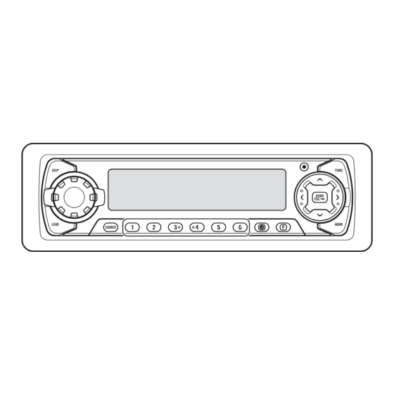
KEH-P5900,P5950 8. OPERATIONS AND SPECIFICATIONS 8.1 OPERATIONS(KEH-P5900) Head Unit BAND/ESC button DISPLAY button FUNCTION button 5/∞/2/3 buttons VOLUME OPEN button selector LOUD button Buttons 1–6 AUDIO button PGM button SOURCE/OFF button CLOCK button Remote Controller (CD-R600) The remote controller (CD-R600) enabling remote control of the head unit is sold separately. - Page 52 KEH-P5900,P5950...
- Page 53 KEH-P5900,P5950...
- Page 54 KEH-P5900,P5950...
- Page 55 KEH-P5900,P5950...
-
Page 56: Specifications
KEH-P5900,P5950 8.2 SPECIFICATIONS General Cassette player(KEH-P5900) Power source ..14.4 V DC (10.8 – 15.1 V allowable) Tape ......Compact cassette tape (C-30 – C-90) Grounding system ........Negative type Tape speed ..4.76 cm/sec. (+0.14cm/sec.,-0.05cm/sec.) Max. current consumption ........10.0 A Fast forward/rewinding time ..