Skipper GDS101 Operation And Installation Manual
Graphic depth sounder
Hide thumbs
Also See for GDS101:
- Operation and installation manual (70 pages) ,
- Replacement procedure (14 pages) ,
- Quick start manual (2 pages)
Table of Contents
Advertisement
Quick Links
Operation and Installation Manual
SKIPPER Electronics AS
Enebakkveien 150
P. O. Box 151, Manglerud
0612 Oslo, Norway
www.skipper.no
Graphic Depth Sounder
GDS101
Telephone:
+47 23 30 22 70
Telefax:
+47 23 30 22 71
E-mail:
support@skipper.no
Co. reg. no:
NO-965378847-MVA
Document no: DM-G001-SB Rev 05.05.14A
Edition: 20110910
Advertisement
Table of Contents

Related Manuals for Skipper GDS101


Summary of Contents for Skipper GDS101
- Page 1 Graphic Depth Sounder GDS101 Operation and Installation Manual SKIPPER Electronics AS Telephone: +47 23 30 22 70 Enebakkveien 150 Telefax: +47 23 30 22 71 P. O. Box 151, Manglerud E-mail: support@skipper.no 0612 Oslo, Norway Co. reg. no: NO-965378847-MVA www.skipper.no Document no: DM-G001-SB Rev 05.05.14A...
- Page 2 SKIPPER Electronics AS GDS101 Operation and Installation Information: Please visit our web site www.skipper.no for additional information. Here you will find product bulletins, software updates, instruction manuals, installation procedures etc. Weitergabe sowie vervielfältigung dieser unterlage, verwertung Copying of this document, and giving it to others and the use...
-
Page 3: Table Of Contents
Repeaters ..................................9 Remote Sounding Control .............................9 Autorange ..................................9 Sound Speed Calibration ...............................9 Fig 1.3 GDS101 Primary Functions......................... 10 2. OPERATION ..........................11 Parameter entry ..............................11 Fig. 2.1 Setting and Parameter Entry Flowchart ....................11 Example of parameter entry ............................12 Operation Screens ............................ - Page 4 SKIPPER Electronics AS GDS101 Operation and Installation Draught ..................................25 External Printer Operation ............................25 Alarm Settings ................................26 Audio warning ................................26 Clock and Calendar Settings ............................26 History Memory ................................26 Simulator ..................................27 Status Screen ................................27 Oscilloscope Screen ..............................27 Nonvolatile Parameter Memory ..........................27 Options ................................27 Repeaters/Slaves .................................27...
- Page 5 SKIPPER Electronics AS GDS101 Operation and Installation Remote Sounding Control............................49 5. START-UP AND SYSTEM ADAPTION ..................50 System Adaptation ............................50 Analogue Output and Log Pulse Input Range Selection .....................50 Language and Units of Measure ..........................50 Remote Transducer Selector ............................50 Low frequency indication ............................50...
-
Page 6: Introduction
61162-1:2007(E) (NMEA 0183) inputs and outputs. Transducers GDS101 is prepared for connection to transducers of the following frequencies: 38, 50 and 200 kHz. One or more of the transducers may be connected at the same time, and the desired transducer may be selected from the operator panel. -
Page 7: Recorded Data Storage
Chapter: 1. Introduction SKIPPER Electronics AS GDS101 Operation and Installation Recorded Data Storage The measured depth and other navigational data is continuously stored in the 24 hour history memory. A standard printer HP Deskjet or Epson D88/LQ300 (all with Centronics parallel interface) may be connected for paper copy. -
Page 8: Fig. 1.2 System Diagram
Chapter: 1. Introduction SKIPPER Electronics AS GDS101 Operation and Installation Navigator IR301 NMEA 0183 Depth repeater Speed log NMEA 0183 NMEA 0183 Cabinet 100/200 ppnm External printer 115/230 VAC/24 VDC 2 x 2.5 sq. mm. Screened Computer system Yard Supply... -
Page 9: Interfacing
Remote Sounding Control * This option lets the GDS101 being remote controlled in synchronized, burst or single ping modes. Autorange This option will automatically adjust the depth range to maintain the bottom contour within the middle half of the screen. -
Page 10: Fig 1.3 Gds101 Primary Functions
Backlight Rotate encoder while Press the Screen Select keeping a key pressed Button repeatedly to cycle to change setting through the primary or menu/screen "Soft-Key" Screens Fig. 1.3 GDS101 Primary Functions Page 10 of 68 Version: 20110910 Sw 05.05.14... -
Page 11: Operation
Chapter: 2. Operation SKIPPER Electronics AS GDS101 Operation and Installation 2. Operation 2. Operation When the installation is complete, and power is connected to the operator unit, the system is switched on-off When the installation is complete, and power is connected to the Operator Unit, the system is switched on by pressing any button. -
Page 12: Example Of Parameter Entry
Chapter: 2. Operation SKIPPER Electronics AS GDS101 Operation and Installation Example of parameter entry Suppose you want to enter a value of 800 m for the depth range. Press the DEPTH RANGE button several times and observe the depth range sequencing through the standard values 10, 50, 100, 500, 1000 m. Press till the range is 500 m. -
Page 13: Primary Operation Screens
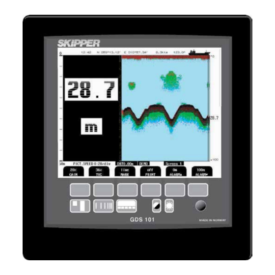
Chapter: 2. Operation SKIPPER Electronics AS GDS101 Operation and Installation Primary Operation Screens Fig. 2.2. Screen 1, Primary Operation screen. This screen shows the main graphic echo gram. Left hand digital indication may be enabled from screen 2. Soft key... -
Page 14: Fig. 2.3. Screen 2, 2Nd Operation Screen
Not used. SYSTEM On/off Switch system off. Switch on with any button. (NOTE: There is still power on the GDS101). * Note: 38 kHz may vary if other frequency options are installed. Page 14 of 68 Version: 20110910 Sw 05.05.14... -
Page 15: Fig. 2.4. Screen 3, 3Rd Operation Screen
Chapter: 2. Operation SKIPPER Electronics AS GDS101 Operation and Installation Fig. 2.4. Screen 3, 3rd Operation screen. This screen shows the main graphic echo gram. Left hand digital indication may be enabled from screen 2. Soft key Name Range/value Default value... -
Page 16: Secondary Operation Screens
Chapter: 2. Operation SKIPPER Electronics AS GDS101 Operation and Installation Secondary Operation Screens 6 ) . ) . Fig. 2.5. Screen 4, Calendar and clock setting. This screen shows the main graphic echo gram. Left hand digital indication may be enabled from screen 2. -
Page 17: Fig. 2.6. Screen 5, Language And Units Of Measure Setup
Chapter: 2. Operation SKIPPER Electronics AS GDS101 Operation and Installation Fig. 2.6. Screen 5, Language and units of measure setup. This screen shows the main graphic echo gram. Left hand digital indication may be enabled from screen 2. Soft key... -
Page 18: Fig. 2.7. Screen 6, Interface Setup Screen
Chapter: 2. Operation SKIPPER Electronics AS GDS101 Operation and Installation Fig. 2.7. Screen 6, Interface setup screen. This screen shows the main graphic echo gram. Left hand digital indication may be enabled from screen 2. Soft key Name Range/value Default value... -
Page 19: Fig. 2.8. Screen 7, History Memory Control Screen
Chapter: 2. Operation SKIPPER Electronics AS GDS101 Operation and Installation Fig. 2.8. Screen 7, History Memory Control Screen. This screen shows the main graphic echo gram. Left hand digital indication may be enabled from screen 2. Soft key Name Range/value... -
Page 20: Fig. 2.9. Screen 8, Nmea Control Screen
Chapter: 2. Operation SKIPPER Electronics AS GDS101 Operation and Installation Fig. 2.9. Screen 8, NMEA control screen. This screen shows list of received or transmitted NMEA messages and half screen echo gram. Soft key Name Range/value Default value Description SCREEN Print Print screen. -
Page 21: Fig. 2.10. Screen 9, System Status Screen
Chapter: 2. Operation SKIPPER Electronics AS GDS101 Operation and Installation Fig. 2.10. Screen 9, System status screen. This screen shows a comprehensive list of system settings and parameters Soft key Name Range/value Default value Description SCREEN Print Print screen. PRINTER... -
Page 22: Fig. 2.11. Screen 10, Oscilloscope Screen
Chapter: 2. Operation SKIPPER Electronics AS GDS101 Operation and Installation Fig. 2.11. Screen 10, Oscilloscope screen. This screen shows receiver output versus time and half screen echo-gram. Soft key Name Range/value Default value Description SCREEN Print Print screen. TRANSDUCER 38, 50, 200 kHz 50 kHz Transducer selection for soft key 3. -
Page 23: Principal Functions
Principal Functions Bottom detection GDS101 employ a bottom detection algorithm that will try to extract the bottom signal from all kinds of noise and secondary echoes. When GDS101 is tracking the bottom normally, a thick black line is shown, and below that, a ribbon with a hatched pattern. -
Page 24: Fixed Key Functions
Chapter: 2. Operation SKIPPER Electronics AS GDS101 Operation and Installation Fixed Key Functions Depth Range The DEPTH RANGE button can be used to set the depth limit between 10 and 1600 m. Standard values available by repeatedly pressing the button are 10, 50, 100, 500 and 1000 m. -
Page 25: Soft Key Functions
Chapter: 2. Operation SKIPPER Electronics AS GDS101 Operation and Installation Soft key Functions Gain The received signal gain may be adjusted from 0 to 100 % to allow for optimal echo levels from bottom and other objects. The gain setting affects signals from all depths. See “Fig. -
Page 26: Alarm Settings
“Fig. 2.5. Screen 4, Calendar and clock setting.” on page 16. History Memory GDS101 has a 24 hour history memory. Depth, time and all available navigation data are stored continuously, so that the last 24 hours of information is always available. The history memory is controlled from screen 7. -
Page 27: Simulator
Each new file will have the full settings in the first lines. Simulator The GDS101 contains a built in simulator to test the screen and various interface signals. The simulator may be switched on and off on screen 9. When the simulator is operating, “DEMO” is flashing at the bottom of the screen. -
Page 28: Auto Range
Chapter: 2. Operation SKIPPER Electronics AS GDS101 Operation and Installation Auto Range This option will automatically adjust the depth range to maintain the bottom contour within the middle part of the screen height. If installed, this option is accessible on screen 3. See “Fig. -
Page 29: User Maintenance
No picture on LCD screen. No AC or DC power to the system. 1. Check switches and fuses on the System is in standby. terminal board inside the GDS101 Too low screen backlight. cabinet. Defective LCD module or interface. 2. Press any button on panel. -
Page 30: Typical Status Screen (9) Contents
If it at all is possible to cycle through the screens and observe this information, several assumptions may be made regarding operation of the GDS101 system. Although some of the subsystems necessary for this basic system operation may still suffer from minor or intermittent operation disorders, the fact that it is possible to select and observe this screen, indicate correct operation of the following GDS101 subsystems: •... - Page 31 Chapter: 3. User Maintenance SKIPPER Electronics AS GDS101 Operation and Installation Symptom Cause Remedy Status screen diagnosis Main voltages out of range • Defective power • Replace terminal board. • + 5 V: <> 4.50 - 5.00 V supply. •...
-
Page 32: Typical Oscilloscope Screen (10) Contents
Chapter: 3. User Maintenance SKIPPER Electronics AS GDS101 Operation and Installation Typical Oscilloscope Screen (10) Contents 15:03 GMT N 13°13.20' E 079°44.5' 14kts 145° 20 mS/div Bot(tom). strength 70% of previous bottom strength (minimum tracking requirement for Filter width: next) -
Page 33: Basic Functionality
Swap NMEA 0183 input wires. listed in the NMEA screen. • NMEA input signals are listed • GDS101 initialization. • Cycle GDS101 power after NMEA in the NMEA screen, but not • Irregular message mnemonic. connection is established. accepted by the GDS101. •... -
Page 34: Installation
Transmission in the air must be avoided! This may cause mechanical damage of the element. Installation Details Refer to SKIPPER’s installation procedures in the appendix and on our web site www.skipper.no regarding information about sea valve, tank installation, welding, cable glands etc. -
Page 35: Fig. 4.1. Basic System Configuration
Chapter: 4. Installation SKIPPER Electronics AS GDS101 Operation and Installation Cabinet 230/115VAC/24VDC 2 x 2.5 sq. mm. Screened Yard Supply Superstructure Transducer Junction Box Hull 1 pair each xducer, 1.5 mm 0-100m cable 2.5 mm 100 -300m cable Steel screened... -
Page 36: Transducer Junction Box
Chapter: 4. Installation SKIPPER Electronics AS GDS101 Operation and Installation Transducer Junction Box The standard cable fitted on the transducer is 25 m or 40 m and may be shortened. The junction box is used to interconnect the transducers fixed cable to a yard supply extension cable if the total required cable length is longer than the standard cable. -
Page 37: Fig. 4.3. Operator Unit
Chapter: 4. Installation SKIPPER Electronics AS GDS101 Operation and Installation peratOr nstallatiOn Fig. 4.3. Operator Unit. Page 37 of 68 Version: 20110910 Sw 05.05.14... -
Page 38: 115/230 V Selection
“Fig. 4.7. Main Wiring Diagram.” on page 115/230 V Selection If the AC power system is 115 V, GDS101 may be prepared for 115 V AC by re-connecting the connectors J102, J103 as shown in “Fig. 4.4. Voltage selection connectors and fuses, terminal board.” on page 39. -
Page 39: Fig. 4.4. Voltage Selection Connectors And Fuses, Terminal Board
Chapter: 4. Installation SKIPPER Electronics AS GDS101 Operation and Installation AC Voltage Selection: Transformer Primary to: J102 for 230V J103 for 115V Fit dummy plug on opposite connector Transformer primary 230 Fuses: J102 V AC J104 Transformer primary 230V AC:... -
Page 40: Fig. 4.5. History Memory Battery Jumper, I/O Board
History Memory Battery Jumper, I/O Board. Note: In the latest GDS101 versions, (starting from Sw 5.05.02) CMOS memory for storing “history” is not used. Here all values are stored on the Compact Flash. The jumper and battery is present only for backward Back-up Battery Jumper compatibility. -
Page 41: Power Indication And Function Leds
Chapter: 4. Installation SKIPPER Electronics AS GDS101 Operation and Installation LD300 LD300 Tranceiver Board Operation LD400: +5V LD401: +12V LD402: +24V LD403: +48V J105 I/O Board Terminal Board LED1 LED1 CPU Board CPU Board Power Fig. 4.6 Function LEDs, Terminal, I/O and CPU Boards. -
Page 42: Fig. 4.7. Main Wiring Diagram
Chapter: 4. Installation SKIPPER Electronics AS GDS101 Operation and Installation Fig. 4.7. Main Wiring Diagram. Page 42 of 68 Version: 20110910 Sw 05.05.14... -
Page 43: Fig. 4.8. Input/Output Circuitry
Chapter: 4. Installation SKIPPER Electronics AS GDS101 Operation and Installation Fig. 4.8. Input/Output Circuitry. Page 43 of 68 Version: 20110910 Sw 05.05.14... -
Page 44: Interfacing
Chapter: 4. Installation SKIPPER Electronics AS GDS101 Operation and Installation Interfacing Alarm relay An alarm relay is provided for interconnection to external alarm systems. This relay is normally energised, and is released by alarm conditions or power failure/power off. See “Fig. -
Page 45: Transmitter Trigger Pulse And Bottom Pulse Outputs
BOTTOM C Collector of output opto coupler, bottom pulse. Analogue interfaces GDS101 is equipped with analogue outputs to supply analogue repeaters or other equipment with analogue inputs. See “Fig. 4.7. Main Wiring Diagram.” on page 42. The signals are galvanically connected to the GDS101. -
Page 46: Fig. 4.10. Data Communication Interfaces
Chapter: 4. Installation SKIPPER Electronics AS GDS101 Operation and Installation Fig. 4.10. Data Communication Interfaces. Page 46 of 68 Version: 20110910 Sw 05.05.14... -
Page 47: Fig. 4.11. Alarm Interconnections
Chapter: 4. Installation SKIPPER Electronics AS GDS101 Operation and Installation Fig. 4.11. Alarm interconnections Page 47 of 68 Version: 20110910 Sw 05.05.14... -
Page 48: External Interface Ports
Chapter: 4. Installation SKIPPER Electronics AS GDS101 Operation and Installation External Interface Ports Ground Stud 5 x PG 13,5 cable entry 10-12 mm XJ303: NMEA ports D-type 9 pin female. XCN6: VGA terminal HDD D-type 15 pin female. XCN3: Printer port D-type 25 pin female. -
Page 49: Options
Hand controller connection Remote Sounding Control. This option lets the GDS101 being controlled remotely in synchronised (edge), burst (level) or single ping modes. If installed, these options are accessible on “Fig. 2.4. Screen 3, 3rd Operation screen.” on page 15. -
Page 50: Start-Up And System Adaption
Chapter: 5. Start-up and system Adaption SKIPPER Electronics AS GDS101 Operation and Installation 5. Start-up and system Adaption System Adaptation Analogue Output and Log Pulse Input Range Selection From “Fig. 2.7. Screen 6, Interface setup screen.” on page 18 it is possible to set number of pulses per nautical mile (100, 200, 400 and 20000) for the log pulse input. -
Page 51: Nmea Setup
$SDDBT,xxxx.x,f,xxxx.x,M,xxx.x,F*hh<CR><LF> Depth below keel $SDDBK,xxxx.x,f,xxxx.x,M,xxx.x,F*hh<CR><LF> [Fore/Aft] transducer $SDXDR,D,x,x,M,c-c,<Cr><Lf> In case of multiple transducer installation, the following SKIPPER proprietary sentence must be selected: $PSKPDPT,x.x,x.x,x.x,xx,xx,c-c*hh<CR><LF> Check sum, possible to turn on/off (see screen 8) Transducer location * Echo sounder channel number (0-99)**... - Page 52 $PSKPSIM,x.x*[CS][CR][LF], where x.x is a simulated depth value. If the depth value is valid (0 - 1600 m), GDS101 will get into simulation mode, where this value is used for all indications and outputs (analogue, NMEA, bottom pulse). The “synthetic” bottom pulse which is generated can be observed on the echogram, “Fig.
-
Page 53: Options
Chapter: 5. Start-up and system Adaption SKIPPER Electronics AS GDS101 Operation and Installation Options Calibration, Sound Speed The only calibration activity necessary is when the sound speed option is installed. In this case, set the required sound speed value in “Fig. -
Page 54: Specifications, Dimensions
Chapter: 6. Specifications, Dimensions SKIPPER Electronics AS GDS101 Operation and Installation 6. Specifications, Dimensions Transducer, 38 kHz Diameter. 181 mm. Mounting. Tank/sea valve/ice tank. Cable length. 40 m. Weight. ca. 20 kg. Protection. IP 68. Transducer, 50 kHz Diameter. 90 mm. -
Page 55: Functional Properties
Chapter: 6. Specifications, Dimensions SKIPPER Electronics AS GDS101 Operation and Installation Functional Properties Display. 10,4” 158 x 211 mm graphic LCD screen with adjustable day/night vision and backlight. 640 x 480 pixels. Printer. HP Deskjet, Epson D88 or Epson LQ300. -
Page 56: Transducer And Junction Box
Chapter: 6. Specifications, Dimensions SKIPPER Electronics AS GDS101 Operation and Installation Environmental according to IEC60945: Transducer and Junction Box Operating temperature. -15 - 55 degree C IEC 60945. Storage temperature. -20 - 70 degree C. Protection, transducer. 6 bar, IP 68. -
Page 57: Service
Chapter: 7. Service SKIPPER Electronics AS GDS101 Operation and Installation 7. Service • All service requests should be made to your local representative or to the manufacturer. (Contact information on title page). • Adjustments and repairs should only be performed by qualified service engineers. -
Page 58: Cpu Board Setup Procedure
Chapter: 8. CPU Board Setup Procedure SKIPPER Electronics AS GDS101 Operation and Installation 8. CPU Board Setup Procedure • Connect a PC keyboard and a VGA screen to the CPU board. • Switch “On” the unit while pressing “Delete” key on the PC keyboard. -
Page 59: Master Reset Procedure
Then press down and keep pressed the soft key to the far right and far left (no. 1 and 6) in the upper row on the GDS101 keyboard. • Turn the GDS101 ‘’on’’ and keep the two soft keys pressed down until you hear 4 ‘’beeps’’ and then release the keys. Upgrading Software New software versions are released from time to time. -
Page 60: Appendix, Miscellaneous Drawings
Chapter: 9. Appendix, Miscellaneous Drawings SKIPPER Electronics AS GDS101 Operation and Installation 9. Appendix, Miscellaneous Drawings For repeater and repeater dimmer, see separate manual: IR301 manual For tank and sea valve, see separate manuals: ETNSLJB-manual. Single bottom sea valve (discontinued from 2007). -
Page 61: Fig. 9.1 Transducer Selector Connection
Chapter: 9. Appendix, Miscellaneous Drawings SKIPPER Electronics AS GDS101 Operation and Installation Fig. 9.1 Transducer Selector Connection Page 61 of 68 Version: 20110910 Sw 05.05.14... -
Page 62: Fig. 9.2 Transducer Selector
Chapter: 9. Appendix, Miscellaneous Drawings SKIPPER Electronics AS GDS101 Operation and Installation Fig. 9.2 Transducer Selector Page 62 of 68 Version: 20110910 Sw 05.05.14... -
Page 63: Fig. 9.3 Cable Gland Connection
Chapter: 9. Appendix, Miscellaneous Drawings SKIPPER Electronics AS GDS101 Operation and Installation Fig. 9.3 Cable Gland Connection Page 63 of 68 Version: 20110910 Sw 05.05.14... -
Page 64: Fig. 9.4 Emc Mounting Kit
Chapter: 9. Appendix, Miscellaneous Drawings SKIPPER Electronics AS GDS101 Operation and Installation Fig. 9.4 EMC Mounting Kit Page 64 of 68 Version: 20110910 Sw 05.05.14... -
Page 65: 10. Notes
Chapter: 10. Notes SKIPPER Electronics AS GDS101 Operation and Installation 10. Notes ---------------------------------------------------------------------------------------------------------------------------------------------- ---------------------------------------------------------------------------------------------------------------------------------------------- ---------------------------------------------------------------------------------------------------------------------------------------------- ---------------------------------------------------------------------------------------------------------------------------------------------- ---------------------------------------------------------------------------------------------------------------------------------------------- ---------------------------------------------------------------------------------------------------------------------------------------------- ---------------------------------------------------------------------------------------------------------------------------------------------- ---------------------------------------------------------------------------------------------------------------------------------------------- ---------------------------------------------------------------------------------------------------------------------------------------------- ---------------------------------------------------------------------------------------------------------------------------------------------- ---------------------------------------------------------------------------------------------------------------------------------------------- ---------------------------------------------------------------------------------------------------------------------------------------------- ---------------------------------------------------------------------------------------------------------------------------------------------- ---------------------------------------------------------------------------------------------------------------------------------------------- ---------------------------------------------------------------------------------------------------------------------------------------------- ---------------------------------------------------------------------------------------------------------------------------------------------- ---------------------------------------------------------------------------------------------------------------------------------------------- ---------------------------------------------------------------------------------------------------------------------------------------------- --------------------------------------------------------------------------------------------------------------------------------------------- ---------------------------------------------------------------------------------------------------------------------------------------------- ---------------------------------------------------------------------------------------------------------------------------------------------- ---------------------------------------------------------------------------------------------------------------------------------------------- ---------------------------------------------------------------------------------------------------------------------------------------------- ---------------------------------------------------------------------------------------------------------------------------------------------- ---------------------------------------------------------------------------------------------------------------------------------------------- ---------------------------------------------------------------------------------------------------------------------------------------------- ---------------------------------------------------------------------------------------------------------------------------------------------- ----------------------------------------------------------------------------------------------------------------------------------------------... -
Page 66: Index
Fig. 1.1 Main Display Unit Panel Layout 7 Alarm interconnections 47 Fig. 1.2 System Diagram 8 Alarm relay 44 Fig 1.3 GDS101 Primary Functions 10 Alarms 9 Fig. 2.1 Setting and Parameter Entry Flowchart 11 Alarm Settings 26 Fig. 2.2. Screen 1, Primary Operation screen. 13 Analogue interfaces 45 Fig. - Page 67 Chapter: 11. Index SKIPPER Electronics AS GDS101 Operation and Installation HISTORY 19 History Memory 26 Parameter entry 11 History Memory Battery Jumper, I/O Board. 40 Performance 55 HOURS 16 PICT.SPEED 17 Picture Speed 24 PING 15, 53 Important note 38...
- Page 68 Chapter: 11. Index SKIPPER Electronics AS GDS101 Operation and Installation SYSTEM 14 System Adaptation 50 System Diagram 8 System (Power) On/Off 23 System Summary 6 Time 52 TRANSDUCER 22 Transducer and Junction Box 56 Transducer Installation 34 Transducer Junction Box 36...
Need help?
Do you have a question about the GDS101 and is the answer not in the manual?
Questions and answers