Table of Contents
Advertisement
Quick Links
Advertisement
Table of Contents

Related Manuals for Aqua Logic AQL-PS-4

Summary of Contents for Aqua Logic AQL-PS-4
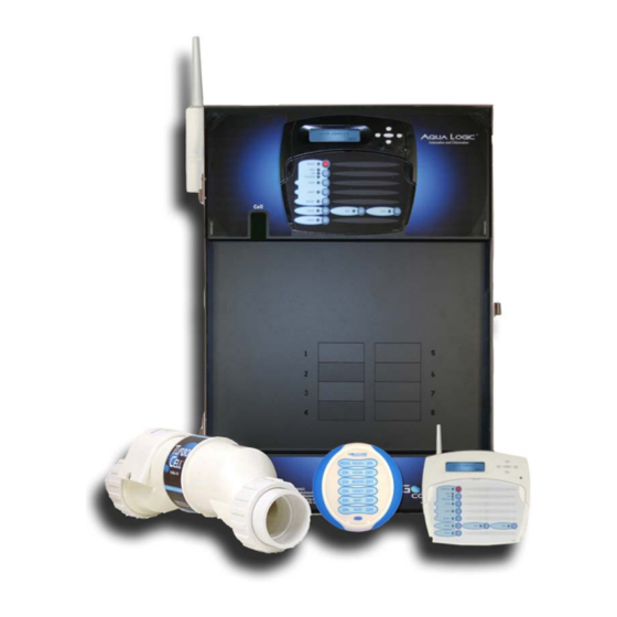
- Page 1 Aqua Logic Aqua Logic Aqua Logic Aqua Logic Aqua Logic Automation and Chlorination (actuators, cell & remote display not included - order separately) Operation Manual for models AQL-PS-4 AQL-PS-8-V AQL-PS-8 AQL-PS-16-V AQL-PS-16 LINE www.goldlinecontrols.com ON TROLS 888-921-7665...
-
Page 2: Important Safety Instructions
IMPORTANT SAFETY INSTRUCTIONS When using this electrical equipment, basic safety precautions should always be followed, including the following: READ AND FOLLOW ALL INSTRUCTIONS • • WARNING: Disconnect all AC power during installation. • WARNING: Water in excess of 100 degrees Fahrenheit may be hazardous to your health. -
Page 3: Table Of Contents
Saturation Index..............33 Water Chemistry Salt Level................34 Type of Salt................34 How to Add or Remove Salt..........34 System Maintenance Servicing and Cleaning the Aqua Logic Cell...... 37 Winterizing................37 Spring Startup................ 37 Troubleshooting & Service Mode ............... 38 Diagnostic Information Check System Indicator............ -
Page 4: Block Diagram
Manual. Aspects of the Aqua Logic that pertain to system setup are not covered in this manual. Automation The AQL-PS-4 (-8, -16) can control up to 4 (8, 16) high voltage (120/240V) pieces of equipment, up to 4 (8 for the PS-16) automatic valve actuators, and 2 conventional heaters plus a solar heater. Both manual and automatic (programmed) operation are available. -
Page 5: Chlorination
Default Display Turn power on at the main panel and turn the Aqua Logic control power circuit breaker on. The keypad will show the default display. The default display alternates between the day/time, air and pool (or spa) temperature, pool/spa sanitizer setting, and salt level. -
Page 6: Output Names
Manual System Operation While the main objective of the Aqua Logic is to automate the operation of your pool/spa system, there may be certain times when you want to override the automatic operation and control the equipment manu- ally. To operate the pool equipment manually while keeping the automation active, perform the following procedures. -
Page 7: Lights And Aux Outputs
Freeze Protection: This function protects the pool, plumbing, and equipment against freeze damage. If Freeze Protection is enabled and the AIR temperature sensor falls below the preset freeze protection temperature (see Filter Pump Configuration), the Aqua Logic will turn on the filter pump to circulate the water. -
Page 8: Heaters
(except for manual turn off for emer- gencies). The red “SERVICE” LED will be illuminated and the Aqua Logic will remain in this mode of operation until manually taken out of service mode. -
Page 9: Using The Programming Buttons
Automatic System Operation The Aqua Logic controls most of your pool equipment automatically in order to minimize the time spent working on your pool. Most of the pool equipment can be programmed to operate on a timeclock basis. In addition, the desired pool and spa temperatures and pool and spa chlorinator settings can be pro- grammed. -
Page 10: Programming Menu Flowchart
Programming Menu Flowchart denotes conditional items PS-4 only PS-4 only... -
Page 11: Settings Menu
The Aqua Logic’s five main menus have many items in each that allow you to customize the operation of your pool/spa equipment. The chart on the previous page shows the Aqua Logic’s five menus as well as each menu’s specific settings. - Page 12 Aqua Logic Super-Chlorinate function. The Aqua Logic will turn on the filter pump, set the pool/spa valves to the correct position, and set the chlorine generator to maximum output.
- Page 13 Move to previous/next menu item Use this function to set the current day of the week and time. These values are used for all the automatic timeclock functions of the Aqua Logic and are also displayed as part of the default menu.
-
Page 14: Timers Menu
Move to previous/next menu item Base NOT Found This menu will only appear if a wireless base station is connected to the Aqua Logic. Perform this procedure each time a wireless remote control is added to the Aqua Logic system. - Page 15 Important: All of the displays shown below use the default generic names for each function or output. The Aqua Logic allows more descriptive names to be assigned to each piece of equip- ment (refer to the section regarding the Configuration Menu for more information).
- Page 16 This menu will appear only if the Lights are configured for countdown timer. This setting is the time after you manually turn on the lights until the Aqua Logic automatically turns off the lights. You can also manually turn off the lights at an earlier time by pressing the LIGHTS button.
- Page 17 Aqua Logic will keep the relay off until these other conditions are suitable for operation. If the Aux1 relay is on during the programmed off time, it may be because of freeze protection.
-
Page 18: Group Function
Superchlorination. Group Function The latest version of the Aqua Logic offers the ability to assign a Group function to a particular button. Instead of a button controlling one particular function, the button can be programmed to initiate a sequence of commands that are programmed in the Configuration Menu. - Page 19 Note that all functions in the table may not be offered. The available functions are dependent on how the Aqua Logic is configured. For example, if the Aqua Logic is configured for a single heater, “Heater2” will not be available as an option in the Group menu. Also, under some circumstances, functions will be displayed but can’t be changed.
-
Page 20: Configuration Menu
Super Chlorinate The Aqua Logic can be programmed to Super Chlorinate the pool or spa while running a group command. When the Group starts, the Super Chlorinate cycle will begin. Super Chlorinate will continue until the preset time expires (see Timers Menu/Super Chlorinate Hours) or until the Group turns off. Changing the Super Chlorinate state using the Settings Menu, the Aqua Pod Super Chlorinate button, or a Super Chlo- rinate assigned Aux/Lights/Valve button will temporarily cancel the Group’s control of Super Chlorinate... - Page 21 This menu will appear only if Pool/Spa Setup is set to “Pool and Spa-Std”. This setting is the time, after you manually switch the Pool/Spa valves to “Spa Only”, until the Aqua Logic automatically returns the valves to their previous positions. It is programmed in increments of 5 minutes, from “Manual On/Off”...
- Page 22 The Aqua Logic allows you to assign any one of a number of names (e.g. “Filter Pump, Pool Filter, Spa Filter, etc.) to the filter relay. This will make the Aqua Logic more user friendly to the homeowner when they want to control the filter equipment. A sheet of small name labels is included with the Aqua Logic main unit and each remote display/keypad so that appropriate pushbuttons can be labeled the same as the name that you have assigned.
- Page 23 If freeze protection is enabled and the AIR temperature sensor falls below the freeze threshold (see below), the Aqua Logic will turn on the filter pump to circulate the water. If “Pool and Spa” is selected in the Pool/Spa sub-menu (see page 24), the valves will also alternate between the pool and spa every 30 minutes and the filter pump will turn off while the valves are turning.
- Page 24 For a Pool/Spa Setup selection of “Pool Only”, “Spa Only” or “Pool and Spa-Std”, Heater1 and/or Heater2 cooldown affect the filter pump. For “Pool and Spa-Dual”, Heater1 is associated with the spa filter and Heater2 with the pool filter. Heater Extend If “Enabled”, the filter extend logic keeps the filter pump running beyond the normal turn-off time until the pool (or spa) is heated up to the desired temperature setting (see Settings Menu).
- Page 25 Move to previous/next configuration menu Lights Name The Aqua Logic allows you to assign any one of a number of names (e.g. “Pool Light, Spa Light, Deck Light, etc.) to this control function. Note that other lights may be assigned to other Aux outputs.
- Page 26 It is important to note that “Solar” must be enabled in the “Solar Config.” menu for proper operation to occur. Low Speed of a 2-Speed Spa Filter Pump – the Aqua Logic will turn on the lights relay whenever the low speed operation of the Dual Equipment Spa filter pump is required. “Pool and Spa-Dual”...
- Page 27 Freeze protection is used to protect the spa and plumbed equipment against freeze damage. If freeze protection is enabled and the AIR temperature sensor falls below the freeze threshold (selectable in Filter Pump Configuration Menu - page 25), the Aqua Logic will turn on the spa filter pump to circulate the water.
- Page 28 It is important to note that “Solar” must be enabled in the “Solar Config.” menu for proper operation to occur. Low Speed of a 2-Speed Spa Filter Pump – the Aqua Logic will turn on the aux relay whenever the low speed operation of the Dual Equipment Spa filter pump is required. “Pool and Spa-Dual”...
- Page 29 Move to previous/next configuration menu Valve3 Name The Aqua Logic allows you to assign any one of a number of names (e.g. “Cleaner Valve, Waterfall valve, Solar Valve, etc.) to each of the valve output control function. This will make the Aqua Logic much more user friendly to the homeowner when they want to turn various valves on or off or program the timeclocks.
- Page 30 Protection is enabled and the AIR temperature falls sensor falls below the selected freeze protection temperature, the Aqua Logic will turn on the valve to allow circulation of the water. IMPORTANT: this only enables operation of the valve3 output during freeze--see the “Filter Pump Config.”...
- Page 31 Note that the function of the Aqua Logic’s built-in display/keypad is unchanged by this selection. Once disabled, the only way to enable “Remote Menus” is to use the local...
- Page 32 > Move to previous/next configuration menu This selection affects ALL of the timeclock logic in the Aqua Logic. If “7-day” is selected, each timeclock will have one set of turn-on/turn-off settings that operate every day of the week. If “Weekend/Weekdays” option is selected then the user can enter one set of turn-on/ turn-off times for the weekend (fixed as Saturday/Sunday) and another set of turn-on/turn- off times for weekdays (Monday through Friday).
-
Page 33: Operate The Spa-Manually
This operation is the highest priority and will take precedence over other automatically programmed operations. At the end of the spa period, the Aqua Logic will return to its normally programmed operation state. Set the Heater Temperature (or turn heater permanently off) 1. -
Page 34: Start/Stop Superchlorination
Note: Separate chlorinator output levels for the pool and spa must be set. If the valves are in the pool-only or spa spillover positions, then the chlorinator will operate per the pool setting. If the valves are in the spa-only position then the chlorinator will operate according to the spa setting. -
Page 35: Enter/Exit Service Mode
2. Pressing the “Service” button rotates through normal operation (red LED off), service mode (red LED on continuously) and service-timed mode (red LED flashing). Note: This operation can only be performed at the main Aqua Logic unit. Both “Ser- vice” and “Service-Timed” disable all automatic programmed operations and allow manual operation from the main unit only. -
Page 36: Saturation Index
Chlorinator Operation / Water Chemistry General Water Chemistry Salt is required only if you are using the chlorinator features on the Aqua Logic Control. If you are NOT using the chlorinator, it is recommended that you follow all of the other chemistry recommendations be- sides salt. -
Page 37: Salt Level
A low salt level will reduce the efficiency of the sanitization and result in low chlorine production. A high salt level can cause the Aqua Logic to stop chlorinating. -
Page 40: Servicing And Cleaning The Aqua Logic Cell
To maintain maximum performance, it is recommended that you open and visually inspect the cell every 3 months or after cleaning your filter. The Aqua Logic will remind you to do this by displaying the message “Inspect/Clean Cell” after approximately 500 hours of operation. -
Page 41: Service Mode
Troubleshooting and Diagnostic Information The Aqua Logic provides 2 different tools to aid in troubleshooting any problems that may occur in your pool and/or spa system. The Service mode will allow you to disable automatic operation and manually control most of the equipment (the heater and general purpose Valve3 output are the exceptions). The Diagnostic Menu will provide some detailed information regarding system operation. -
Page 42: Diagnostic Menu
Simply press either the “+” or “-“ key to start a new cycle. The Aqua Logic periodically reverses the polarity of the voltage applied to the cell in order to automatically clean off any calcium deposits. It is important that you check the chlorinator operation in both polarities. -
Page 43: Instant Salt
If the display is “Open Circuit” or “Short Circuit” then check the wiring to the sensor and also make sure that the wires are secure in the terminal block in the Aqua Logic main unit. Main Software No function Revision 2.40... - Page 44 The following statement is applicable if any of the wireless accessories are connected to the Aqua Logic system. FCC Statement (Compliance Statement, Part 15.19): This device complies with Part 15 of the FCC Rules. Operation is subject to the following two conditions: (1) This device may not cause harmful interference, and (2) this device must accept any interference received, including interference that may cause undesired operation.
-
Page 45: Aqua Logic Warranty
If written proof of the date of the initial system installation is not provided to Goldline, the manufacturing datecode on the Aqua Rite, Aqua Trol, or Aqua Logic electronics unit will be the sole determinant of the date of the initial system installation. - Page 46 TEST IDEAL RANGE ADJUSTMENT REQUIRED Free Chlorine 1.0 - 3.0 ppm Turn output dial up to increase, down to decrease -OR- increase or decrease pump filtration time. Too high - add muriatic acid 7.2 - 7.6 Too low - add soda ash. Add baking soda to increase.
Need help?
Do you have a question about the AQL-PS-4 and is the answer not in the manual?
Questions and answers