
Subscribe to Our Youtube Channel
Related Manuals for Cebora SOUND MIG 3840/T Pulse


Summary of Contents for Cebora SOUND MIG 3840/T Pulse
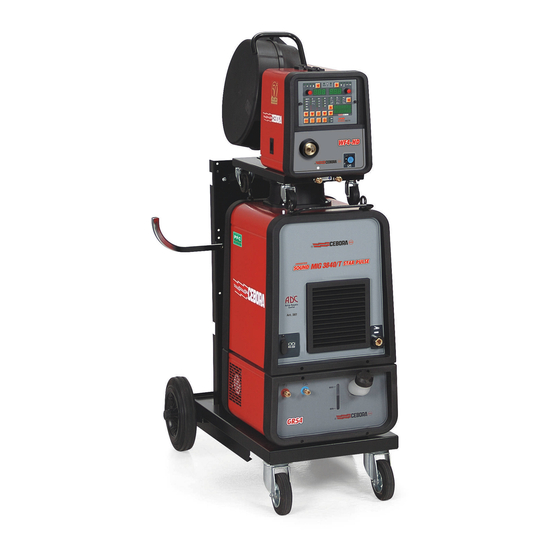
- Page 1 CEBORA S.p.A. SOUND MIG 3840/T Pulse POWER SOURCE + COOLING UNIT + WIRE FEEDER art. 287 SERVICE MANUAL 3.302.191 15/02/05...
-
Page 2: Table Of Contents
- SYSTEM DESCRIPTION ..........................5 - Introduction..............................5 - Technical specifications..........................5 - Description of SOUND MIG 3840/T Pulse system (art. 287)..............5 - Description of MIG3840/T Pulse power source................... 6 - Description of WF4-P Wire Feeder......................8 2.5.1 - Accessories table............................ - Page 3 CEBORA S.p.A. - Error codes and alarm signals........................36 3.7.1 - 2 - EEPROM error........................... 36 3.7.2 - 6 - Communication error on CAN-BUS, detected by control board (543)..........36 3.7.3 - 9 - Communication error on the CAN-BUS between control panel (324) and control board (543)..36 3.7.4 - 10 - Missing voltage and current at the power source output.
-
Page 4: General Information
1.1 - Introduction. The purpose of this manual is to train personnel assigned to carry out maintenance on the SOUND MIG 3840/T Pulse multi-process welding system, art. 287. 1.2 - General service policy. It is the responsibility of the customer and/or operator to use the equipment appropriately, in... -
Page 5: System Description
“firmware Cebora” (programs releasable from the Cebora site) and to insert them in the machines that have to be programmed or updated. The version of the inserted programs, is visible during start-up in the control panel, in the following form (see fig. -
Page 6: Description Of Mig3840/T Pulse Power Source
CEBORA S.p.A. Customizations of the welding system modes (parameter set-up) and the welding programs created by the operator are saved in the EEprom in the micro board (543). In order to concur the substitution of micro board (543) without to lose these data, the EEprom is mounted on socket so as to be able to be removed from the board and being inserted in one new board. - Page 7 CEBORA S.p.A. The 540 Vdc voltage present at the output of the rectifier bridge is applied to the flyback board (539), which acts as a main power source and generates the service voltages for the various system circuits (power source, wire feeder, control panel).
-
Page 8: Description Of Wf4-P Wire Feeder
CEBORA S.p.A. The “-”(BO) power output of the power source is located on the front panel, while the “+”(BR) power output is located on the rear panel. They must be connected to the wire feeder differently according to the type of welding to be carried out (see Instruction Manual). -
Page 9: Accessories Table
CEBORA S.p.A. The following accessories may currently be connected to the connector (BB): 2.5.1 - Accessories table. Torch recognition signal Art. Description art. Active signals. (pins 16-15 of BB). 1243 MIG torch Start (from central adapter 0 Vdc ((BB) free). -
Page 10: Maintenance
CEBORA S.p.A. 3 - MAINTENANCE WARNINGS ANY INTERNAL INSPECTIONS OR REPAIRS MUST BE CARRIED OUT BY QUALIFIED PERSONNEL. BEFORE BEGINNING MAINTENANCE OPERATIONS, UNPLUG THE MACHINE FROM THE MAINS AND WAIT FOR THE INTERNAL CAPACITORS TO DISCHARGE. THE DISCHARGE TIME FOR THE DC-CAPACITORS (561) IS HEAVILY AFFECTED BY THE OPERATING MODE OF THE FLYBACK BOARD (539). -
Page 11: Control Panel Commands And Signals
CEBORA S.p.A. 3.3 - Control panel commands and signals. 3.302.191 15/02/05... -
Page 12: Operating Sequences
CEBORA S.p.A. 3.4 - Operating sequences. The following sequences reflect proper machine operation. They may be used as guidelines for troubleshooting. After each repair, they must be carried out without encountering any error or impediment. Given the various operating modes available, due to the different possible configurations, only the main sequence for each welding process is described below. -
Page 13: Mig Mode
CEBORA S.p.A. type of material (existing material and gas types may be selected using the (AM) and (AX) buttons). ♦ Each time the button (AH) is pressed, the leds Y-Z-AA-AB-AC-AD-AE-AF-AG light in sequence, in observance of the conditions imposed by the selected “Process”... -
Page 14: Tig Operation
CEBORA S.p.A. Correct? NO (see 3.5.9, 3.5.10, 3.5.11). Release the torch start button. ♦ The arc is immediately shut off and the wire feed stopped, while gas flow stops after the post-gas stage (the post-gas time is activated only if the power source has delivered current). -
Page 15: Mma Mode
CEBORA S.p.A. Correct? NO (see 3.5.9, 3.5.10). Release the torch start button. ♦ The arc shuts off immediately if a long ramp time is not set (slope-down). ♦ The gas flow ends after the post-gas period (the post-gas time is activated only if the power source has delivered current). -
Page 16: Troubleshooting
CEBORA S.p.A. 3.5 - Troubleshooting. WARNINGS ANY INTERNAL INSPECTIONS OR REPAIRS MUST BE CARRIED OUT BY QUALIFIED PERSONNEL. BEFORE REMOVING THE PROTECTIVE GUARDS AND ACCESSING INTERNAL PARTS, DISCONNECT THE POWER SOURCE FROM THE MAINS AND WAIT FOR THE INTERNAL CAPACITORS TO DISCHARGE. - Page 17 CEBORA S.p.A. POWER SUPPLY TEST. Flyback board (539), connector J5, terminals 1 (+) and 4 (-) = +540 Vdc. Correct? ♦ Check the wiring between J5 flyback board (539) and J6 pre-charge board (562). ♦ After waiting for the DC-capacitors (561) to completely discharge, temporarily disconnect connector J5 on flyback board (539).
- Page 18 CEBORA S.p.A. ♦ With the power source off, temporarily disconnect the connectors J6, J8 and J10 on flyback board (539) and make sure that on J18, terminals 1 (+) - 6 (-) on motor control board (232) voltage = +55 Vdc. If correct, identify which of the three...
-
Page 19: Power Source Powered, Control Panel On, Fan (512) Stopped
CEBORA S.p.A. 3.5.2 - Power source powered, control panel on, fan (512) stopped. NOTE The fan (512) on the power source is controlled by the interface board (543), and its operation depends on the power source conditions, as shown in the par. 2.4, Description of MIG3840/T Pulse power source. -
Page 20: System Powered, Display And Signals Do Not Show The Correct Values
♦ Check the compatibility of the programs on the three boards, comparing the installed version indexes with the specifications cited on the Cebora Web site. These programs must be in compatible versions, thus if any one of these 3 boards is replaced, you must make sure of this compatibility;... -
Page 21: The Start Button Produces No Effect
CEBORA S.p.A. COMMANDS AND SIGNALS TEST. The keys on control panel (324) allow all of the steps regarding the selection of “Process”, “Mode” and “Programs”, as described in par. 3.4 Operating sequences, and in the Instruction Manual. Correct? ♦ Check the supply voltages of the control panel (324), motor control board (232) - Page 22 CEBORA S.p.A. motor control board (232). If >Mohm in both directions, (circuit broken) replace the connector board (225). ♦ Replace the connector board (225) and/or motor control board (232). START COMMAND TEST. Connector board (225), terminal J4-1 (-) and J4-2 (+) = 0 Vdc with start button pressed, +12 Vdc with button released (either with button connected to the central adapter (BA), or with button connected to the connector (BB)).
-
Page 23: Some Signals From Connector For Accessories (Bb) Do Not Work
CEBORA S.p.A. 3.5.5 - Some signals from connector for accessories (BB) do not work. NOTES The “start” and “arc-on” signals are exchanged with the motor control board (232) in clear, thus directly; all of the other signals are converted into serial information and exchanged via the internal RS232 serial line, inserted in the connections between J3 on connector board (225) and J7 on motor control board (232). -
Page 24: System Powered, No Gas Flows From The Torch
CEBORA S.p.A. 3.5.6 - System powered, no gas flows from the torch. SOLENOID VALVE (227) TEST. Solenoid valve (227) terminals = 24 Vdc with start button pressed, in MIG or TIG mode, or with button (AQ) on control panel pressed (test gas). -
Page 25: System Powered, The Wire Feeder Motor Does Not Work
CEBORA S.p.A. 3.5.7 - System powered, the wire feeder motor does not work. WIRE FEEDER MOTOR (404) TEST. Motor control board (232), connector J19, terminals 1 (-) and 2 (+) = +17 Vdc, in MIG mode, with button (AR) on control panel pressed (fixed speed wire test). -
Page 26: In Open Circuit Operation, The Output Voltage Is Not Regular
CEBORA S.p.A. 3.5.8 - In open circuit operation, the output voltage is not regular. OPEN-CIRCUIT OUTPUT VOLTAGE TEST. Output terminal (-) (BO), and output terminal (+) (BR) on power source = approximately +68 Vdc, (in MIG and TIG modes with start button pressed, in MMA with the only the MMA process selected). - Page 27 CEBORA S.p.A. the diode group (567) and the central terminal connected to the output terminal (+)(BR) of the power source. Correct value = junction of one diode in one direction, >Mohm with the probes reversed. If you find short-circuits or breaks, replace the diode group (567).
- Page 28 CEBORA S.p.A. ♦ Check the wiring between J2 and J3 of interface board (543) and driver boards (548). ♦ With power source off, and connectors J2 and J3 disconnected from interface board (543), check the resistance on the following connectors of the driver boards (548): L+ (+) and L- (-) = approx.
-
Page 29: In Resistive Load Operation, The Output Voltage Is Not Regular
CEBORA S.p.A. 3.5.9 - In resistive load operation, the output voltage is not regular. NOTE In TIG and MMA processes, the circuits to detect the short-circuit at the output prevent the power source from delivering current if the load is already applied at the output. Under normal operating conditions, the load is applied when the power source already delivers a voltage greater than the minimum set in the control. - Page 30 CEBORA S.p.A. unbalance in one of the three phases, check the wiring between pre-charge board (562), chokes (516+522), filter board (542) and switch (504). Restore any deteriorated connections and replace any damaged components. ♦ Replace the pre-charge (562) and/or filter (542) boards and/or chokes (516+522).
-
Page 31: In Mig Or Tig Mode, Arc Difficult To Strike, The Arc Shuts Off Immediately After Striking (Stuttering Start-Up)
Upgrade if necessary by connecting to the Cebora Web site (see par. 2.3 - Description of SOUND MIG 3840/T Pulse system (art. 287) and instructions on the Web site). -
Page 32: In Mig Mode, When The Start Button Is Released, The Wire Sticks To The Workpiece (Ineffective Motor Braking)
If you encounter problems, make sure the software versions installed in the welding system are compatible. Upgrade if necessary by connecting to the Cebora Web site (see par. 2.3 - Description of SOUND MIG 3840/T Pulse system (art. 287)). -
Page 33: Cooling Unit Gr54 Does Not Work Correctly
CEBORA S.p.A. 3.5.14 - Cooling unit GR54 does not work correctly. NOTE Operation of the GR54 cooling unit depends on the welding process selected, and it may be enabled or disabled via a setting on the control panel (324) (see Instruction Manual). - Page 34 CEBORA S.p.A. Correct? ♦ Check the wiring between the terminals 2 and 4 on pre-charge board (562), fuse (BN) on rear panel and fast-on connector (inserted in the wiring between cooling unit and power source). ♦ Check fuse (BN) on power source rear panel. If tripped, replace and make sure resistance on fast-on connector terminals (inserted in the wiring between cooling unit and power source).
-
Page 35: Kit Driver + Igbt, Code 5.710.511 Replace Instructions
CEBORA S.p.A. 3.6 - Kit Driver + igbt, code 5.710.511 replace instructions. 3.6.1 - Removing igbt modules from heatsink and preparing heatsink. - Remove the two igbt modules. - Remove the two thin sheets of metal Therm-strate covered with grease and inserted between the heatsink and the igbt modules. -
Page 36: Error Codes And Alarm Signals
CEBORA S.p.A. 3.7 - Error codes and alarm signals. 3.7.1 - 2 - EEPROM error. Block due to software error. Replace the control board (543). 3.7.2 - 6 - Communication error on CAN-BUS, detected by control board (543). Communication error between control board (543) and motor control board (232), or between control board (543) and control panel (324), detected by MASTER control, on control board (543). -
Page 37: 14 - Microprocessor Supply Voltage Error On Control Board (543)
CEBORA S.p.A. 3.7.6 - 14 - Microprocessor supply voltage error on control board (543). Perform the CONTROL BOARD (543) POWER SUPPLY TEST in par. 3.5.2, paying special attention to the 8 Vdc and 5 Vdc voltages. 3.7.7 - 16 - Direct current voltage at pre-charge board (562) output below minimum permitted value. -
Page 38: 41 - Connector Board (225) Missing Or Disconnected
CEBORA S.p.A. 3.7.11 - 41 - Connector board (225) missing or disconnected. CONNECTOR BOARD (225) CONNECTED TEST. Motor control board (232), terminals 1(+) and 2(-) of OP4 = approximately +1.2 Vdc, with power source powered. Correct? ♦ Check flat cable between J3 connector board (225) and J7 of motor control board (232). -
Page 39: 52 - "Trg" On Display (O). In Mig And Tig Mode, Start Button Pressed Upon Start-Up
CEBORA S.p.A. board (232). Correct value = junction of one diode in one sense and 1 Kohm with the probe terminals reversed. If incorrect, replace the motor control board (232). ♦ With power source off, temporarily disconnect the flat cable from J7 on motor control board (232) and power up the power source again. -
Page 40: 57 - "Mot" On Display (O). Excessive Wire Feeder Motor (404) Current
CEBORA S.p.A. In MMA mode it may also derive from an interruption in the output voltage detection line. In any case, in addition to cleaning the torch, check: – wiring between connector J13 of interface board (543) and output terminals (-)(BO) and output (+)(BR);... -
Page 41: 75 - "H2O" On Display (O). Low Pressure In The Cooling Circuit
CEBORA S.p.A. proportional to the temperature, and thus difficult to check. If necessary replace the thermostat board (551). − Check the wiring between J1 interface board (543), and thermostat board (551) on igbt group (548). − Make sure that on J1 of control board (543), terminals 3(+) and 4(-) voltage = +5 Vdc. If incorrect, with power source off, temporarily disconnect J1 on control board (543) and check the resistance between terminals 3 and 4 of the patch connector disconnected from J1. -
Page 42: Components List
CEBORA S.p.A. 4 - COMPONENTS LIST 4.1 - Power source art. 287 : see file ESP287.pdf enclosed at the end of the manual. 4.2 - Table of components: see file ESP287.pdf enclosed at the end of the manual. 4.3 - List of spare parts. -
Page 43: Electrical Diagrams
CEBORA S.p.A. 5 - ELECTRICAL DIAGRAMS 5.1 - Power source art. 287 : see file SCHE287.pdf enclosed at the end of the manual. 5.2 - Waveforms. 5.2.1 - Speed feedback signal from the wire feeder motor encoder (404)(par. 3.5.7). (in MIG wire test mode, thus with button (AR) pressed, fixed speed). -
Page 44: Output Current Feedback Signal On Resistive Load (Par. 3.5.9)
CEBORA S.p.A. 5.2.4 - Output current feedback signal on resistive load (par. 3.5.9). 5.2.5 - Wire feeder motor (404) voltage during correct braking (par. 3.5.13). 5.2.6 - Wire feeder motor (404) voltage during incorrect braking (par. 3.5.13). 5.2.7 - “PRECHARGE” signal (par. 3.7.5). -
Page 45: Filter Board (542) Code 5.602.196/B
CEBORA S.p.A. 5.3 - Filter board (542) code 5.602.196/B. 5.3.1 - Topographical drawing. 5.3.2 - Connector table. Connector Terminals Function IN-L1 phase 1 mains input. IN-L2 phase 2 mains input. IN-L3 phase 3 mains input. OUT-L1 phase 1 mains output. -
Page 46: Pre-Charge Board (562) Code 5.602.187/A
CEBORA S.p.A. 5.4 - Pre-charge board (562) code 5.602.187/A. 5.4.1 - Topographical drawing. 5.4.2 - Connector table. Connector Terminals Function L1-L2-L3 three-phase mains input. VDC+1 +540 Vdc power output. VDC+2 +540 Vdc power output. VDC-1 0 Vdc power output. VDC-2 0 Vdc power output. -
Page 47: Flyback Board (539) Code 5.602.184/E
CEBORA S.p.A. 5.5 - Flyback board (539) code 5.602.184/E. 5.5.1 - Topographical drawing. 5.5.2 - Connector table. Connector Terminals Function 1-2(+) - 4-5(-) +55 Vdc output for motor control board (232) power supply. 1(+) - 4(-) +540 Vdc input for flyback board (539) power supply. -
Page 48: Interface Board (543) Code 5.602.186
CEBORA S.p.A. 5.6 - Interface board (543) code 5.602.186. 5.6.1 - Topographical drawing. 5.6.2 - Connector table. Connector Terminals Function 3(+) - 4(-) +5 Vdc output for thermostat board (551) power supply. igbt group (548) temperature signal input. 1(GL1) - 2(EL1) igbt L1 drive signal output. -
Page 49: Micro Board (543) Code 5.602.185/C
CEBORA S.p.A. 5.7 - Micro board (543) code 5.602.185/C. 5.7.1 - Topographical drawing. 5.7.2 - Connector table. Connector Terminals Function -15 Vdc output for current transducer (529) power supply. power source output current input. +15 Vdc output for current transducer (529) power supply. -
Page 50: Igbt-Driver Board (548) Code 5.602.188
CEBORA S.p.A. 5.8 - Igbt-driver board (548) code 5.602.188. 5.8.1 - Topographical drawing. 5.8.2 - Connector table. Connector Terminals Function H+ - H- drive signal input for igbt H (H1 or H2). L+ - L- drive signal input for igbt L (L1 or L2). -
Page 51: Motor Control Board (232) Code 5.602.103/B
CEBORA S.p.A. 5.11 - Motor control board (232) code 5.602.103/B. 5.11.1 - Topographical drawing. 3.302.191 15/02/05... - Page 52 CEBORA S.p.A. 5.11.2 - Connector table. Connector Terminals Function 1 - 2 wire feed unit door open signal input. 1 - 2 CAN-BUS communication line, with control panel. 3(+) - 4(-) +5 Vdc for CAN-BUS with control panel power supply.
-
Page 53: Connector Board (225) Code 5.602.104/B
CEBORA S.p.A. 5.12 - Connector board (225) code 5.602.104/B. 5.12.1 - Topographical drawing. 5.12.2 - Connector table. Connector Terminals Function 1 - 2 connector board (225) power supply input. 1(+) - 3(-) ARC-ON signal input. 6(+) - 4(-) torch recognition signal output. -
Page 54: Control Panel (324) Cod. 5.602.110/C
CEBORA S.p.A. 5.13 - Control panel (324) cod. 5.602.110/C. 5.13.1 - Disegno topografico. 5.13.2 - Connector table. Connector Terminals Function 1(+) - 2(-) +8 Vdc input for control panel (324) power supply. signals bus between panel board and micro board inside control panel (324).
Need help?
Do you have a question about the SOUND MIG 3840/T Pulse and is the answer not in the manual?
Questions and answers