Table of Contents
Advertisement
EQUIPMENT
SELECTION
. . . . . . . . . . . . .
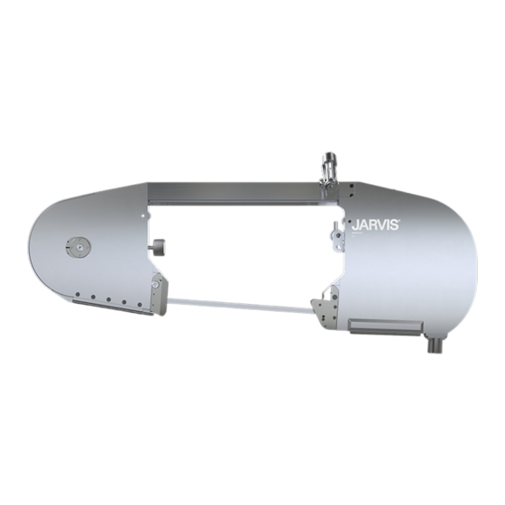
Buster V Band Saw
460/230V--60Hz
380/220V--50Hz
Spring Balancer
. . . . . . . . . . . . . . . .
Air Balancer (4 feet overall length) 4042016
Air Balancer (20 feet overall length) 4042020
Standard Blade (127 in)
Cut Tooth Blade (127 in)
JET Blade (127 in)
. . . . . . . . . . . . .
JARVIS
6206002;::::
Model Buster V
Beef Splitting Band Saw
Ordering No.
. . . . . . . . . .
4006033
. . . . . . . . . .
4006057
4042052
. . . . . . . . .
1023159
. . . . . . . .
1023338
1023620
TABLE OF
CONTENTS
. . . . . . . . . . . . . . . . . . . . . . . . .
• Motor Wiring Diagrams
®
. . . . . . . . . . . . . . . . . . .
. . . . . . . . . . . .
. . . . . . . . . . . . . . . . . . .
. . . . . . . . . . .
. . . . . . . . . . . .
. . . . . . . . .
. . . . . . . . . . .
jarvis.products.corp@snet.net
.jarvisproducts.com
Page
2
4
10
10
12
13
15
Advertisement
Table of Contents

Related Manuals for Jarvis Buster V


Summary of Contents for Jarvis Buster V
-
Page 1: Table Of Contents
......Page • Safety Messages to Employer and Buster V Band Saw Safety Director .... -
Page 2: Safety Messages To Employer And Safety Director
8. Avoid injury. Do not permit the tool to be misused. 9. If you resell or distribute a Jarvis product, you must provide the purchaser with the appropriate safety sheets and tool brochure. Additional copies of safety sheets and tool brochures will be provided upon request. -
Page 3: Safety Messages To Operators, Maintenance And Cleanup Personnel
Model Buster V page 3 of 16 Keep hands clear. SAFETY MESSAGES TO OPERATORS, MAINTENANCE AND CLEANUP PERSONNEL REMOVE ANY MALFUNCTIONING TOOL FROM SERVICE REPORT ANY PROBLEMS TO YOUR SUPERVISOR 1. Disconnect the power supply in accordance with OSHA’s lockout/tagout procedures (29 CFR 1910.147) before making any blade changes. - Page 4 Model Buster V page 4 of 16 IDLER END Figure A * Tighten to 37 lbf--ft ** Use grease gun 8038001 ITEM PART NO. PART NAME 1055862 Flat Head Screw 1004275 Washer 1060030 Hex Head Threaded Insert...
-
Page 5: Products Corporation
Model Buster V page 5 of 16 DRIVE END Figure B * Tighten to 37 lbf--ft ** Tighten to 80 lbf--ft using wrench 8039120 ITEM PART NO. PART NAME 1061614 Internal Water Manifold 1055499 Pan Head Screw ITEM PART NO. -
Page 6: 1008077 460/230V, 60 Hz
Model Buster V page 6 of 16 ITEM PART NO. PART NAME 1036103 Thrust Bushing 1013244 Internal Retaining Ring 1020144 Torque Knob Shaft Torque Knob 1030067 Woodruff Key Assembly 1021259 Flanged Bearing Race 1035163 O-ring 1007041... - Page 7 Model Buster V page 7 of 16 ITEM PART NO. PART NAME 1055721 Socket Set Screw, Cup Pt. Hanger Assembly 1042125 Hanger Bracket 1021493 Cylindrical Bearing 1028040 Pin and Shackle Link Assy. 1055469 Socket Set Screw, Cup Pt.
-
Page 8: Parts Diagram And List
Model Buster V page 8 of 16 ITEM PART NO. PART NAME 1055304 Hex Head Screw 1018113 Trigger Lever with item 5 1010273 Threaded Pin Electric Handles for Export Tools 1014096 Spring 1021314 Bushing 1013181 External Retaining Ring... - Page 9 Model Buster V page 9 of 16 Electric Motor with Smooth Housing ITEM PART NO. PART NAME 1055321 Socket Head Cap Screw 1002342 Motor Cover 1035456 O--ring 1021240 Ball Bearing 3064001 Rotor Assembly 1013211 Retaining Ring...
-
Page 10: Specifications
Model Buster V page 10 of 16 Electric Control ITEM PART NO. PART NAME Box Assembly 1017110 Wiring Diagram, 115V 1017111 Wiring Diagram, 220V 1017085 Electrical Danger Label 1063311* Pigtail Fuse, 115V... -
Page 11: Products Corporation
The coil op- erating voltage is indicated on the label (item 1, page 10) inside the control box cover. 2.3 The connection between the Buster V and the control box is pre- -wired and is approximately 22 feet long. -
Page 12: Operation Instructions
S Move hanger bracket (item 2, page 7) toward lem to your supervisor immediately. the rear of the Buster V to tip the nose of the saw down. 2.2 Make sure that the Buster V moves freely on its balancer. -
Page 13: Maintenance Instructions
With the tool run- ning, release one trigger and the tool should 3.4.1 The drive end of the Buster V should be low- stop. Continue holding the depressed trigger er than the idler end while sawing through and then depress the other trigger. -
Page 14: Wrench
2.1.10 Work each ball plunger up and down with a available. wooden dowel to lubricate the springs. 1.3 Check the front bearings: 2.1.11 Apply Jarvis 1315 White Grease to the ball plunger surface and to the bearing (item 9, 1.3.1 Grease the front wheel bearings through page 6). -
Page 15: Products Corporation
Model Buster V page 15 of 16 Nine Wire Motor Hook- -up 1017301 Six Wire Motor Hook- -up 1017296 JARVIS PRODUCTS CORPORATION ® 33 ANDERSON ROAD, MIDDLETOWN, CONNECTICUT 06457-4926 jarvis.products.corp@snet.net UNITED STATES OF AMERICA EMAIL. .jarvisproducts.com TEL. 860-347-7271 FAX. -
Page 16: Products Corporation
Model Buster V page 16 of 16 PRODUCTS CORPORATION JARVIS PRODUCTS CORPORATION ® JARVIS PRODUCTS CORPORATION 33 ANDERSON ROAD, MIDDLETOWN, CONNECTICUT 06457--4926 ® jarvis.products.corp@snet.net UNITED STATES OF AMERICA EMAIL. 33 ANDERSON ROAD, MIDDLETOWN, CONNECTICUT 06457-4926 • • WWW.jarvisproducts.com TEL. 860--347--7271 FAX.
Need help?
Do you have a question about the Buster V and is the answer not in the manual?
Questions and answers
how many amps spend a buster IV splitting saw