Mitsubishi Electric MSZ-FD09NA Service Manual
Hide thumbs
Also See for MSZ-FD09NA:
- Operating instructions manual (36 pages) ,
- Installation manual (8 pages) ,
- Quick start manual (9 pages)
Table of Contents
Advertisement
SPLIT-TYPE AIR CONDITIONERS
INDOOR UNIT
SERVICE MANUAL
Models
MSZ-FD09NA
MSZ-FD12NA
NOTE:
RoHS compliant products have <G> mark on the spec name plate.
• 3. SPECIFICATION has been corrected.
Please void OBH497 REVISED EDITION-B.
Outdoor unit service manual
MUZ-FD•NA Series (OBH498)
MXZ-A·NA Series
CONTENTS
2. PART NAMES AND FUNCTIONS ····················· 4
3. SPECIFICATION ················································ 5
4. OUTLINES AND DIMENSIONS ························ 7
5. WIRING DIAGRAM ············································ 8
6. REFRIGERANT SYSTEM DIAGRAM ··············· 9
7. SERVICE FUNCTIONS ··································· 10
8. MICROPROCESSOR CONTROL ··················· 12
9. TROUBLESHOOTING ····································· 22
10. DISASSEMBLY INSTRUCTIONS ···················· 36
PARTS CATALOG (OBB497)
No. OBH497
REVISED EDITION-C
(OB444)
·······································
3
Advertisement
Table of Contents
Troubleshooting

Related Manuals for Mitsubishi Electric MSZ-FD09NA


Summary of Contents for Mitsubishi Electric MSZ-FD09NA
-
Page 1: Table Of Contents
• 3. SPECIFICATION has been corrected. Please void OBH497 REVISED EDITION-B. SPLIT-TYPE AIR CONDITIONERS INDOOR UNIT No. OBH497 SERVICE MANUAL REVISED EDITION-C Models MSZ-FD09NA MSZ-FD12NA Outdoor unit service manual MUZ-FD•NA Series (OBH498) MXZ-A·NA Series (OB444) CONTENTS 1. TECHNICAL CHANGES ·······································... -
Page 2: Revision C
Revision A: • 3. SPECIFICATION has been corrected. Revision B: • 3. SPECIFICATION has been corrected. Revision C: • 3. SPECIFICATION has been corrected. -
Page 3: Technical Changes
TECHNICAL CHANGES MSZ-FD09NA MSZ-FD12NA 1. New model. -
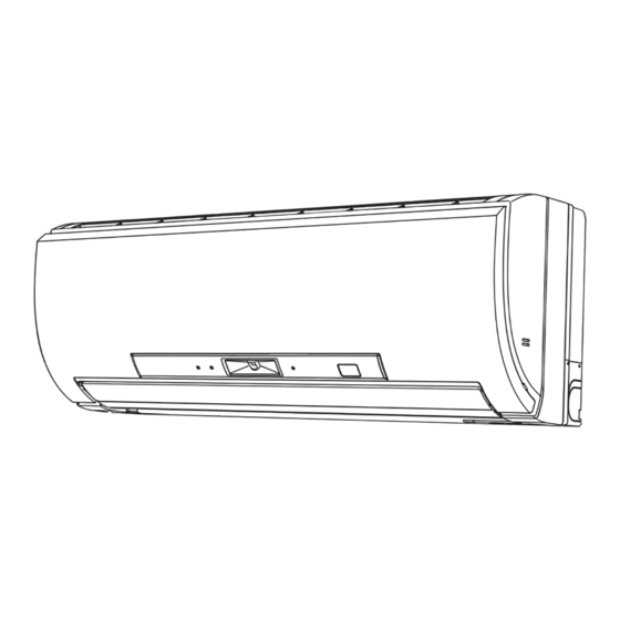
Page 4: Part Names And Functions
PART NAMES AND FUNCTIONS MSZ-FD09NA MSZ-FD12NA AREA lamp POWER lamp Remote control Operation indicator receiving section lamp Front panel Air filter Air inlet Remote controller Platinum deodorizing filter Anti-allergy Enzyme Filter i-see Sensor Air outlet Emergency operation switch Horizontal vane... -
Page 5: Specification
SPECIFICATION Indoor model MSZ-FD09NA MSZ-FD12NA Power supply V, phase, Hz 208/230 , 1 , 60 Max. fuse size (time delay)/ Disconnect switch Min. circuit ampacity Fan motor F.L.A 0.76 COOL Dry 162 - 226 - 339 - 381 162 - 226 - 381 - 410 Airfl... - Page 6 (ft./sec.) sec., when air is blown out horizontally HEAT 19.2 27.7 from the unit properly at the High speed 17.1 24.7 MSZ-FD09NA position. COOL 15.5 22.4 The coverage should be used only as a general guideline since it varies HEAT 21.2...
-
Page 7: Outlines And Dimensions
OUTLINES AND DIMENSIONS MSZ-FD09NA MSZ-FD12NA Unit: inch 7/16 X 1 Oblong hole 7/16 X 13/16 Oblong hole 8-7/8 8-7/8 2-1/2 2-1/2 Installation plate 31-3/8 30-7/8 6-1/8 6-1/8 2-1/8 13-9/16 2-11/16 Indoor unit Wall hole ø2-9/16 Air in Installation plate 10-1/8... -
Page 8: Wiring Diagram
WIRING DIAGRAM MSZ-FD09NA MSZ-FD12NA... -
Page 9: Refrigerant System Diagram
REFRIGERANT SYSTEM DIAGRAM MSZ-FD09NA MSZ-FD12NA Unit:inch Refrigerant pipe (with heat insulator) Indoor coil Indoor thermistor heat RT12 (main) exchanger Flared connection Indoor coil thermistor RT13 (sub) Room temperature thermistor RT11 Flared connection Refrigerant pipe (with heat insulator) Refrigerant flow in cooling... -
Page 10: Service Functions
SERVICE FUNCTIONS MSZ-FD09NA MSZ-FD12NA 7-1. TIMER SHORT MODE For service, set time can be shortened by short circuit of JPG and JPS the indoor electronic control P.C. board. The time will be shortened as follows. (Refer to 9-7.) Set time: 1-minute... - Page 11 7-3. AUTO RESTART FUNCTION When the indoor unit is controlled with the remote controller, the operation mode, the set temperature, and the fan speed are memorized by the indoor electronic control P.C. board. “AUTO RESTART FUNCTION” automatically starts operation in the same mode just before the shutoff of the main power. Operation If the main power has been cut, the operation settings remain.
-
Page 12: Microprocessor Control
MICROPROCESSOR CONTROL MSZ-FD09NA MSZ-FD12NA WIRELESS REMOTE CONTROLLER Signal transmitting section Operation display section VANE CONTROL button OPERATE/STOP FAN SPEED CONTROL button (ON/OFF) button OFF TIMER button OPERATION SELECT button ON TIMER button POWERFUL button TIME SET buttons Temperature buttons FORWARD button... - Page 13 8-1. COOL ( ) OPERATION (1) Press OPERATE/STOP (ON/OFF) button. POWER lamp of the indoor unit turns on with a beep tone. (2) Select COOL mode with OPERATION SELECT button. (3) Press TEMPERATURE buttons (TOO WARM or TOO COOL button) to select the desired temperature. The setting range is 61 ~ 88°F (16 ~ 31°C).
- Page 14 8-4. AUTO CHANGE OVER ··· AUTO MODE OPERATION Once desired temperature is set, unit operation is switched automatically between COOL and HEAT operation. Mode selection (1) Initial mode When unit starts the operation with AUTO operation from off: • If the room temperature is higher than the set temperature, operation starts in COOL mode. •...
- Page 15 (3) Positioning To confirm the standard position, the vane moves until it touches the vane stopper. Then the vane is set to the selected angle. Confirming of standard position is performed in the following cases: (a) The operation starts or finishes (including timer operation). (b) The test run operation starts.
- Page 16 (10) POWERFUL ( ) operation. The air conditioner automatically adjusts the fan speed and the set temperature, and operates the POWERFUL mode. The POWERFUL mode is automatically released 15 minutes after operation starts, and the operation mode returns to the mode prior to POWERFUL operation 2.
- Page 17 8-6. i-see CONTROL OPERATION The sensors constantly measure the room and floor/wall temperatures to automatically adjust to the set temperature by esti- mating the temperature actually perceived by a person inside the room (“sensory temperature”). Advantages · The air inside the room is conditioned quickly to a comfortable condition. ·...
- Page 18 Indoor unit installation location and air-conditioning area Installed at left Installed at center Installed at right LEFT RIGHT LEFT RIGHT LEFT RIGHT ·Be sure to set the slide switch inside the remote controller to an appropriate position in accordance with the installed position of the indoor unit.
- Page 19 Operation and operating range i-see sensor moves 30 degrees from the center in both right and left side. i-see Sensor turning to the right i-see Sensor turning to the center i-see Sensor turning to the left i-see Sensor operates as follows in accordance with AREA setting made with the remote controller. “AUTO”...
- Page 20 8-8. TIMER OPERATION 1. How to set the time (1) Check that the current time is set correctly. NOTE: Timer operation will not work without setting the current time. Initially “0:00 AM” blinks at the current time dis- play of TIME MONITOR, so set the current time correctly with CLOCK SET button. How to set the current time (a) Press the CLOCK set button.
- Page 21 8-9. EMERGENCY/TEST OPERATION In case of test run operation or emergency operation, use EMERGENCY OPERATION switch on the right side of the indoor unit. Emergency operation is available when the remote controller is missing, has failed or the batteries of the remote controller run down.
-
Page 22: Troubleshooting
TROUBLESHOOTING MSZ-FD09NA MSZ-FD12NA 9-1. CAUTIONS ON TROUBLESHOOTING 1. Before troubleshooting, check the following 1) Check the power supply voltage. 2) Check the indoor/outdoor connecting wire for miswiring. 2. Take care of the following during servicing 1) Before servicing the air conditioner, be sure to turn off the unit first with the remote controller, and then after confirming the horizontal vane is closed, turn off the breaker and/or disconnect the power plug. -
Page 23: Failure Mode Recall Function
9-2. FAILURE MODE RECALL FUNCTION Outline of the function This air conditioner can memorize the abnormal condition which has occurred once. Even though LED indication listed on the troubleshooting check table (9-4.) disappears, the memorized failure details can be recalled. This mode is very useful when the unit needs to be repaired for the abnormality which does not recur. - Page 24 2. Indoor unit failure mode table Abnormal point POWER Condition Correspondence (Failure mode) Not lighted Normal — — The room temperature thermistor short or open 1-time fl ash every Room temperature Refer to the characteristics of the room temperature circuit is detected every 8 seconds during op- 0.5-second thermistor thermistor (9-7.).
- Page 25 9-3. INSTRUCTION OF TROUBLESHOOTING Start Indoor unit operates. Indoor unit does Indoor unit oper- OPERATION INDICATOR Outdoor unit does not receive the ates. lamp on the indoor unit is not operate normally. Outdoor unit signal from re- fl ashing on and off. mote controller.
-
Page 26: Troubleshooting Check Table
9-4. TROUBLESHOOTING CHECK TABLE Before taking measures, make sure that the symptom reappears for accurate troubleshooting. When the indoor unit has started operation and the following detection method has detected an abnormality (the first detection after the power ON), the indoor electronic control P.C. board turns OFF the indoor fan motor with OPERATION INDICATOR lamp flashing. - Page 27 L AREA R POWER Abnormal Operation indicator lamp Symptom Condition Correspondence point POWER lamp is lighted. The operation mode of the each indoor unit AREA lamps fl ash. Outdoor unit MXZ type is differently set to COOL (includes DRY) and •...
- Page 28 9-5. TROUBLE CRITERION OF MAIN PARTS MSZ-FD09NA MSZ-FD12NA Part name Check method and criterion Figure Room temperature therm- Measure the resistance with a tester. istor (RT11) Refer to 9-7. "Test point diagram and voltage", "Indoor electronic control P.C. Indoor coil thermistor board", the chart of thermistor.
-
Page 29: Troubleshooting Flow
9-6. TROUBLESHOOTING FLOW A Check of indoor fan motor The indoor fan motor error has occurred, and the indoor fan does not operate. Turn OFF the power supply. Pay careful attention to the high voltage on the fan motor connector CN211. Turn ON the power supply, wait 5 seconds or more, and then press EMERGENCY OPERATION switch. - Page 30 B Check of remote controller and indoor electronic control P.C. board Check if the remote controller is exclusive for this air conditioner. Press OPERATE/STOP (ON/OFF) button on the remote controller. Is LCD display on the remote controller Replace the batteries. (Refer to 9-1.4.) visible? (Not clear) Remove the batteries, then set them back...
- Page 31 C Check of indoor electronic control P.C. board and indoor fan motor Turn OFF the power supply. Remove indoor fan motor connector CN211, vane motor connector CN151 and the i-see Measure the resistance of the i-see Short/open circuit: Sensor motor connector CN110 from the Sensor motor coil.
- Page 32 D How to check miswiring and serial signal error Turn OFF the power supply. Is there rated voltage in the Check the power supply. power supply? Turn ON the power supply. Is there rated voltage between outdoor terminal block S1 and Check the wiring.
- Page 33 E Electromagnetic noise enters into TV sets or radios Is the unit grounded? Ground the unit. Is the distance between the antennas Extend the distance between the antennas and and the indoor unit within 9.91 ft., or is the indoor unit, and/or the antennas and the the distance between the antennas and outdoor unit.
- Page 34 9-7. TEST POINT DIAGRAM AND VOLTAGE MSZ-FD09NA MSZ-FD12NA Indoor electronic control P.C. board 5 VDC 12 VDC Cement resistor (R111) Indoor fan motor (CN211) 294/325 VDC (-) Fiducial terminal of cathode side on measur- ing high-voltage DC 15 VDC (+)3 - 6 VDC...
- Page 35 2. Power monitor receiver P.C. board 3. Monitor P.C. board...
-
Page 36: Disassembly Instructions
Locking lever lever. Connector MSZ-FD09NA MSZ-FD12NA NOTE:Turn OFF power supply before disassembling. OPERATING PROCEDURE PHOTOS 1. Removing the panel Photo 1 (1) Hold both sides of the front panel and lift the front panel until it is level. - Page 37 OPERATING PROCEDURE PHOTOS 2. Removing the electronic control P.C. board, the Photo 2 power monitor receiver P.C. board, i-see Sensor, SW P.C. board and the terminal block Screw of the (1) Remove the panel (refer to 1.) and the corner box. conduit cover (2) Remove the screw of the conduit cover.
- Page 38 OPERATING PROCEDURE PHOTOS Photo 5 3. Removing the electrical box (1) Remove the panel (refer to 1.) and the corner box. (2) Remove the indoor/outdoor connecting wire, the sensor holder, the electrical cover and the ground wire. (Refer to 2.) (3) Disconnect the following connectors on the electronic con- trol P.C.
- Page 39 OPERATING PROCEDURE PHOTOS 6. Removing the horizontal vane motor Photo 8 Screws of the horizontal (1) Remove the nozzle assembly. (Refer to 4.) vane motor unit cover (2) Remove the screws of the horizontal vane motor unit, and pull out the horizontal vane motor unit. (3) Remove the screws of the horizontal vane motor unit cover.
- Page 40 HEAD OFFICE: TOKYO BLDG., 2-7-3, MARUNOUCHI, CHIYODA-KU, TOKYO 100-8310, JAPAN © Copyright 2008 MITSUBISHI ELECTRIC CO.,LTD Distributed in Nov. 2008. No. OBH497 REVISED EDITION-C 5 Distributed in Apr. 2008. No. OBH497 REVISED EDITION-B 7 Distributed in Mar. 2008. No. OBH497 REVISED EDITION-A 7 New publication, effective Nov.