Table of Contents
Advertisement
Quick Links
Advertisement
Table of Contents

Related Manuals for Zaxcom MAXX


Summary of Contents for Zaxcom MAXX
-
Page 2: Table Of Contents
Table of Contents KNOW YOUR MAXX ................................5 ....................................5 RONT ANEL ....................................... 7 ....................................8 IGHT ......................................9 ................................10 CREEN ETERS ................................12 CREEN XPLAINED Transport Status .................................. 12 Timecode ..................................... 12 Headphone Selection................................12 Battery Status Indicator ..............................12 Save Indicator .................................. - Page 3 Link Input ..................................30 TRANSMITTER SETUP ............................... 31 ............................... 31 RANSMITTER NABLE ..............................31 RANSMITTER REQUENCY ................................ 31 RANSMITTER ............................... 31 RANSMITTER OWER ..............................31 RANSMITTER OURCE AUTOMIX ..................................32 A-Mix Mode ..................................32 Mic On Threshold ................................32 Attack ....................................32 Decay ....................................
- Page 4 AutoPan....................................55 MEDIA RECOMMENDATIONS ............................56 Compact Flash Cards ................................56 SYNCING MAXX TO A DENECKE SLATE ..........................57 CONNECTOR PIN ASSIGNMENTS ............................58 Audio Input / Output Connectors (XLR-3) ..........................58 Tape / Mono Out - Uses a Switchcraft TA5-F ........................58 Return / Audio Inputs 5 and 6 - Uses a Switchcraft TA5-F ....................
- Page 5 PRODUCT SUPPORT ................................. 61 MAXX SPECIFICATIONS ..............................62 ZAXCOM WARRANTY POLICY AND LIMITATIONS ......................63...
-
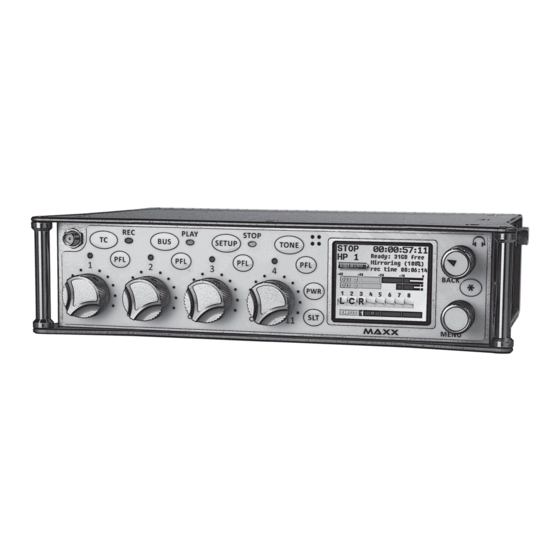
Page 6: Know Your Maxx
In the Warning Setup Menu Maxx can be set up that if you are recording just to the primary folder the LED will flash red, and when Maxx is mirroring the LED will go to solid red. This is to warn the user that Maxx is not in Continuous Mirror Mode. - Page 7 • A quick press will power up Maxx. • Press and hold for 3 seconds to power down Maxx. Release the key when the countdown reaches 1. • When Auto-Pan is ON the power key will change the panning for the active channel.
-
Page 8: Left Side
2. AES Input Output connector / GPI (DE-15F) Maxx has AES 2 input pairs and 3 AES output pairs. The Input has a sample-rate conversion, allowing each input to have a different sampling-rate. Maxx will accept any unlocked AES signal with a sampling-rate of 44.1 to 96 kHz. -
Page 9: Right Side
Right Side 1. Headphone (1/4” stereo jack) 2. External Power connector (Hirose- HR10A-7P-4P) 10 to 18 VDC {1/2 A @ 12 VDC} 3. Tape / Mono Out (TA-5M) Outputs both the Tape and Mono Out busses. The tape and mono out are both balanced mono sources. The audio that is fed to these busses are controlled from the Mono / Tape bus matrix. -
Page 10: Rear
Rear 1. Mic/Line-level Inputs 3 and 4 (Combo XLR-3F 1/4" Stereo ) 2. Mic/Line-level Inputs 1 and 2 (XLR-3F) -
Page 11: Home Screen / Meters
ENG / EFP Bag Operation ENG Home Screen ENG Quick Pan Matrix with AES Inputs ENG Home Screen Only on Maxx with AES Option Red Record Enabled Indicators – Show which tracks will be recorded Yellow ISO Attenuation Enabled Indicators -... - Page 12 Zaxcom Maxx Meters Explained Output Buses Input signal from XLR Inputs Input Meter Screen Output Busses Digital Inputs with Virtual Faders AutoTrim Meter Digital Input Virtual Fader Screen Only on Maxx with AES Option...
-
Page 13: Home Screen Explained
Save Indicator A moving pixel on bottom of screen moving right to left indicates that the Maxx is saving a parameter setting to Maxx’s ROM memory. If you power down while the pixel is moving the settings will not be saved. -
Page 14: Main Menu
MAIN MENU Meta Data / Playback Main Menu To access the Main Menu press the MENU knob. Scroll for additional menu items NOTE: If you are in the Virtual Fader Screen or the ENG Screen and have the Virtual Fader enabled you have to press and hold the MENU knob for 1 second to enter the Main Menu. -
Page 15: Record Card / Mirror Menu
Bus Assignments Cross Points, Compressor Enables (input, output and card), High Pass Filters and Notch Filters. Write Sound Report When you select this, Maxx will create a Sound Report and write it on the Mirror CF card file. The sound report contains the Meta Data information for what was recorded. -
Page 16: Primary Compact Flash Folder Menu
In the event of a power loss Maxx automatically closes any open files to the point the audio recording was interrupted with no loss of audio up to that point. Even though Maxx uses a proprietary file system, it is 100% compatible with Mac or PC by using the free file conversion utility ZaxConvert. -
Page 17: Format Card
MAIN MENU Recording Setup / Primary Folder Format Card This menu allows you to format the CF card. This process will take about 2 minutes to complete. ISO Attenuation NeverClip™ inputs allow large signals to travel through the digital mixing engine using 32 bit floating point numbers. Once these large signals are recorded into a 24-bit WAV (or MARF) file, the advantage of floating point math is lost and these signals can clip if you don’t use a card limiter. -
Page 18: Iso Attenuation Enable
MAIN MENU Recording Setup / Primary Folder ISO Attenuation Enable This menu allows you to choose which record tracks you choose to attenuate. Edit Current Folder To edit the folder name 1. Scroll down to the Edit Current Folder Name. 2. -
Page 19: Mirror Enables
MAIN MENU Recording Setup / Mirror Enables Mirror Enables This menu controls which of the tracks are copied on to Maxx’s Mirror file. Maxx without the ISO record option will only display two mirror tracks. SHORTCUT: It is not necessary to remove record enable cross points from the Mirror Matrix. If a Primary card track is not assigned, it will NOT be recorded and not written to the Mirror file. -
Page 20: Mirror Settings Menu
• ON: Maxx will only start to mirror once the unit stop recording. • CONTINUOUS: When Maxx is recording, the audio is copied to the mirror folder as is written to the primary folder. Depending on the track count, the mirror card may lag behind a bit. Not to worry, after you go into Stop mode, the mirror card will catch up. -
Page 21: File Type
A BWAV MONO file is 1 file per track. So if you record 1 track only, 1 file will represent that "take" from the time you press record to the time you press stop. If you were to record 2 tracks for that same take, the Maxx will produce 2 files, one representing track 1 and the other representing track 2. -
Page 22: Record Routing
You can choose between all 6 analog inputs, or the 2 output busses. If Maxx is equipped with the AES option you can also assign the digital inputs as well. -
Page 23: Fader Assign Matrix
Number Maxx is a digital mixer, so no actual audio is going through the fader controls allowing for complete flexibility for the hardware faders. Any one of the analog inputs 1-5, digital inputs 1-4 (available on Maxx with AES option), or analog trim can be assigned to any of the 4 hardware faders. -
Page 24: Store / Recall
MAIN MENU Memory Menu Memory Menu Memory Store Positions Memory Recall Positions Scroll for additional menu items Store / Recall From this page, you can save and recall three full setups for different scenarios. All user set parameters are saved and can be recalled as needed. -
Page 25: Factory Reset
Note and Track presets. To do a full restore - including Note and Track names hold the stop key on boot up. Store / Recall using the Compact Flash Card Maxx also has the option to save settings to (and restore settings from) the mirror Compact Flash card. This allows settings to be exchanged between multiple machines. -
Page 26: About Maxx Menu
MAIN MENU About Maxx About Maxx Menu This menu gives you information about your Maxx Software Version Indicates current CPU Usage. -
Page 27: Mode Menu
This menu sets up Maxx’s engineering parameters. Scroll for additional menu items Sample Rate This is where the sample rate that Maxx will record file at is selected. Maxx can record with sample-rates of: 44100, 47952, 48000, 48048, 88200, 96000, 192000 Selected Sample Rate When recording files at a high sample rate of 88200, 96000 or 192000 there are some limitations to Maxx’s recording... -
Page 28: Prerecord
Prerecord This allows you to have Maxx buffer the audio in a prerecord buffer. You can choose to buffer up to 5 seconds of audio. From the point the Maxx is powered up, it is always processing data, and any sound coming in from any input is always being processed. -
Page 29: Transport Keys
MAIN MENU Mode Menu Transport Keys SHIFTED If the TC, BUS or SETUP key is pressed, the items associated with those keys will open. To go into Record, Playback or Stop, it is necessary to SHIFT those keys. You will need to press the MENU knob to “SHIFT” while simultaneously pressing the REC, PLAY or STOP key to go into that mode. -
Page 30: Vfader Mode
This will attenuate the AES output level by the amount selected in the menu. The AES attenuation will allow you to take full advantage of the dynamic range of the Never Clip inputs. The output attenuation works the same way as the ISO attenuation on Maxx’s record tracks works. The adjustable range is from 1dB to 20dB in 1dB increments. -
Page 31: Meter Peak Hold
Link Input When set to ON the link input allows Maxx to receive the AES mix bus output from another Maxx / Nomad, or any other AES source. The received AES audio channels are mixed individually to the output bus of Maxx. This links the two... -
Page 32: Transmitter Setup
This sets the source of audio that will feed the UHF camera link transmitter. • OUT 12 - Maxx will transmit what is being sent to the output buses 1 and 2. • TAPE / MONO-Maxx will transmit what is being sent to tape and mono output buses. -
Page 33: Automix
Maxx’s Auto-Mixer has no limit on the number of microphones that can be active at one time. The Auto-Mixer also has a last microphone on feature; this means that even if no one is speaking there will always be one microphone included in the mix, which will be the last active microphone. -
Page 34: Attenuation
MAIN MENU AutoMix Setup Menu Attenuation Sets how much each microphone is attenuated when it is closed. • Attenuation can be set between -10dB and -80dB NOTE: When a microphone is closed the level of that input is actually attenuated rather than muted. The level of attenuation is adjustable by the Attenuation setting. -
Page 35: Eng Setup
MAIN MENU ENG Setup / Advanced Setup ENG Setup This menu sets up Maxx’s engineering parameters. Scroll for additional menu items Scroll for additional menu items Compressor Enable This matrix lets you set which card tracks, output busses, and if the tape out or mono out will have their compressor / limiters enabled. -
Page 36: Input Compressor Parameters
MAIN MENU ENG Setup / Advanced Setup Input Compressor Parameters This menu lets you set the parameters for the Input Compressors. The Input Compressor settings are global, meaning that the settings adjusted here will the same for all Input Channels. Output Compressor Parameters This menu lets you set parameters for the Output Compressors. -
Page 37: Headphone Names
MAIN MENU ENG Setup / Advanced Setup Headphone Names This menu allows you to customize the headphone monitor names that appear in the home screens. Once you click on a HP number, you will be taken to the Enter Text page (p.44) Track Names This menu allows for the naming of record tracks. -
Page 38: Note Presets
The notes can be up to 22 characters long. Input Levels This menu allows you to adjust the audio input levels for the slate, camera returns and on Maxx with the AES option the digital inputs. -
Page 39: Output Levels
Volume Level of warning beep to the main headphones If set to ON the record LED will blink if Maxx is not mirroring as it is recording to the primary folder. This menu manages the audible alerts sent to the headphones. These warnings will also be displayed on the LCD screen. -
Page 40: Lcd Screen Brightness
Adjusts the brightness of Maxx’s LCD Screen. The LCD screen brightness adjusts from 0 to 11. LED Brightness Adjusts the brightness of Maxx’s LEDs. This is a global setting meaning that all LED lights will be set to the same brightness. The LED brightness adjusts from 0 to 30. -
Page 41: Advanced Setup Menu
Randomly entering in code numbers can cause your Maxx to lock up, permanently. It will need to be sent in for service. Allow Logging If this is set to ON it allows Maxx to log warning and error messages as well as status. The logged messages are displayed on the log screen. Log Screen... -
Page 42: Slate Always On
MAIN MENU ENG Setup / Advanced Setup Slate Always On • Normal - This is the typical setting that would be used. With this setting pressing and holding the slate key will activate the slate mic. • Forced - When you activate the slate mic this setting locks the slate mic in the on position. Note a power cycle will deactivate the slate mic and the default this mode back to normal. -
Page 43: Pressing The Timecode Key
3V coin cell battery. • JAM TC - Jams Maxx’s TC from an external source, such as a camera or a master TC unit. • JAM UB - Jams Maxx’s User-Bits from another source, such as a camera or a master TC unit. -
Page 44: Enter Timecode
MAXX OPERATIONS Timecode Enter Timecode Manually Entering Timecode 1. Press the MENU knob to highlight the TC. 2. Rotate the MENU knob to select the desired entry position. 3. Press the keys to enter a numeric value. 4. Once you enter the last digit, the TC is entered immediately and jammed NOTE: If you don’t enter the entire eight digits, press the MENU knob to force the jam. -
Page 45: Timecode Setup
TC Displayed This sets what time code that Maxx displays • GENERATOR – The time code that is displayed is from Maxx’s internal time code generator. • CARD – Time code is displayed from the file being recorded or played back. -
Page 46: Set Date
Set Date This sets Maxx’s internal calendar. Timecode Routing This menu sets the function of the BNC timecode connector. • OUTPUT - Maxx will output timecode on the BNC connector. • INPUT - Maxx will receive timecode on the BNC connector... -
Page 47: Pressing The Bus Key
Analog Inputs Tone Slate Digital Inputs appear only on Maxx with AES option. The top line of the three pages indicates the following sources: • Analog Inputs 1-6 • T - Tone • S - Slate •... -
Page 48: Tape/Mono Out Matrix
This matrix sets what audio is routed to the Tape and Mono out connector. Any of the inputs, including digital inputs, or output busses can be routed indecently to the tape and or the mono out. Maxx without AES option Maxx with AES option Card Track Tone Enable This matrix assigns TONE to the record tracks. -
Page 49: Pressing The Setup Key
MAXX OPERATIONS Input Setup Pressing the Setup key Analog Input Setup Pressing the Setup key will take you to the analog Setup menu where you can adjust the parameters of the 4 analog inputs. Input Compressor with Adjustable Notch Filters available Stereo Linking (See below –... -
Page 50: Headphone Setup
MAXX OPERATIONS Pre Fader Listen Headphone Setup Left Ear Right Ear Check the Enable box to include this monitor configuration while cycling through the HP Setting up your Headphone There are 10 individual Headphone matrices available to store a monitor configuration consisting of any combination of the following: •... -
Page 51: Pre Fader Listen
Listening to Inputs Pressing the PFL keys puts Maxx into Pre Fader Listen mode. The PFL will follow the fader assignment. Once one of the PFL keys is pressed, the name in the Headphone Monitor field is replaced with PFL alternating with the selected channel number(s) that you are monitoring. -
Page 52: Setting Up And Engaging Tone
Adjusting Tone Tone level and frequency can be adjusted in the ENG SETUP menu. Adjusts Tone Frequency Adjusts Tone Level Engaging Tone To toggle tone generation on / off, press and hold the TONE key on the face of Maxx. -
Page 53: Enter Text
MAXX OPERATIONS Entering Text Enter Text This menu allows alphanumeric data entry for all parameters that require data input. • To enter a character, turn the MENU knob until the character is highlighted and then press the MENU knob to select it. -
Page 54: False Start
MAXX OPERATIONS False Start False Start Pressing the STOP key a second time after can mark a Take as a False Start or just delete it. After you press STOP, if you press and hold the STOP key for 1 second, the False Start page will be displayed. -
Page 55: Eng /Efp Bag Operation
MAXX OPERATIONS ENG / EFP Bag Operations ENG /EFP Bag Operation This Mode was created to aid in mixing and recording when in a “run and gun” situation. This mode makes panning and mixing all inputs easily accessible right from the ENG Home screen. -
Page 56: Autopan
MAXX OPERATIONS ENG / EFP Bag Operations AutoPan AutoPan eliminates the need for a separate hardware pan key for each input. AutoPan can be enabled in the Mode menu. When it is enabled and a fader is “touched”, two things come into play: •... -
Page 57: Media Recommendations
SanDisk and Transcend cards, it is not necessary to use cards with “double write speed” features. Any cards, 4 – 64 GB, should be fine. Also 133X cards are fine - a faster card will not make Maxx write any faster - the only advantage of a faster card is faster downloads. -
Page 58: Syncing Maxx To A Denecke Slate
Syncing Maxx to a Denecke Slate The LTC stream out of Maxx has a “jitter” in the TC signal at 29.97 fps and 23.976 fps. This can result in the Denecke TS-C or the TS-3 slates identifying the wrong code, if you set the slate to “Auto Set” (position 5). In addition, if you use “Auto Set”... -
Page 59: Connector Pin Assignments
Zaxcom Maxx User’s Manual Connector Pin Assignments Connector Pin Assignments Audio Input / Output Connectors (XLR-3) XLR - 3 Signal PIN 1 GROUND PIN 2 SIGNAL + PIN 3 SIGNAL - Tape / Mono Out - Uses a Switchcraft TA5-F... -
Page 60: Headphone
SLEEVE AES Digital Input / Output Connectors (DB-15) Maxx uses a mini DB-15 (AKA: DE-15) connector for the AES Digital input and output connectors. Top row pins: 5, 4, 3, 2, 1 Middle row pins: 10, 9, 8, 7, 6... -
Page 61: Updating Firmware
2. Insure that a set of fully charged batteries are installed or a stable power supply is connected. 3. With Maxx powered down, insert the CF card containing the .bin file into the card slot. Make sure only one .bin file is on the card. -
Page 62: Product Support
Zaxcom Maxx User’s Manual Product Support Product Support Register your Maxx with Zaxcom: http://www.zaxcom.com/product-registration Download the latest Firmware from: http://www.zaxcom.com/software-updates Download the latest User Manuals from: http://www.zaxcom.com/instruction-manuals Submit Technical Questions at: http://www.zaxcom.com/submit-a-technical-question Submit information for Repair Services at: http://www.zaxcom.com/repairs Join the Zaxcom Forum at:... -
Page 63: Maxx Specifications
Maxx Specifications Analog In Recording Analog inputs: 4 Mic/line-level with 48V phantom power and 2 Track count: 8 tracks Line level / camera returns Bit-depth (primary card): 24 bits Connector: 4 x XLR-3F (2 with .25” jack) Bit-depth (mirror card): 16 / 24 bits Mic level input range: -56 to -26 dBu Sample rates (kHz): 44.1, 47.952, 48, 48.048, 96,192... -
Page 64: Zaxcom Warranty Policy And Limitations
Distributers may sell Products to resellers who then sell Products to end users. Please see below for warranty information or obtaining service. No warranty service is provided unless the product is returned to Zaxcom Inc. or a Zaxcom dealer in the region where the Product was first shipped by Zaxcom.
Need help?
Do you have a question about the MAXX and is the answer not in the manual?
Questions and answers