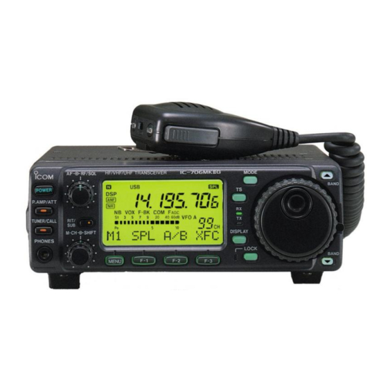
Icom IC-706MKIIG Service Manual
Hf/vhf/uhf all mode transceiver
Hide thumbs
Also See for IC-706MKIIG:
- Service manual (86 pages) ,
- Instruction manual (76 pages) ,
- Quick start manual (15 pages)
Table of Contents
Advertisement
Advertisement
Table of Contents

Related Manuals for Icom IC-706MKIIG


Summary of Contents for Icom IC-706MKIIG
- Page 1 HF/VHF/UHF ALL MODE TRANSCEVER S-14411XZ-C1 June. 2007...
- Page 2 8. READ the instructions of test equipment throughly before connecting a test equipment to the transceiver. Icom, Icom Inc. and logo are registered trademarks of Icom Incorporated (Japan) in the United States, the United Kingdom, Germany, France, Spain, Russia and/or other countries.
-
Page 3: Table Of Contents
CONTENTS SECTION SPECIFICATIONS SECTION INSIDE VIEWS SECTION CIRCUIT DESCRIPITON RECEIVER CIRCUITS............3-1 TRANSMITTER CIRCUITS . -
Page 4: Specifications
SECTION 1 SPECIFICATIONS ¤GENERAL ¤RECEIVER • Frequency coverage • Receive system Receive 0.030 – 200.000 MHz* SSB/CW/AM/WFM Double superheterodyne 430.000 – 470.000 MHz* Triple superheterodyne Transmit 1.800 – 1.999 MHz* • Intermediate frequencies 3.500 – 3.999 MHz* MODE 1st IF 2nd IF 3rd IF 7.000 –... - Page 5 SECTION 2 INSIDE VIEWS • MAIN AND FILTER BOARDS FILTER board D/A converter (IC2201: M62352GP) RX preamplifier MAIN CPU clock (IC151: PC1658G) (X2161: CR-636) MAIN CPU * HPF board (IC 2001: HD6433337YA56F) 1st mixer (D271: HSB88WSTR) MAIN board 1st IF filter 3rd IF filter for FM * (FI511: FI-261) (FI791: SFPC455E-TC01)
-
Page 6: Circuit Descripiton
SECTION 3 CIRCUIT DESCRIPTION • Used RF high-pass filter (HPF board) 3-1 RECEIVER CIRCUITS Control Entrance Frequency Control Entrance Frequency 3-1-1 HF/50 MHz RF CIRCUIT signal coil (MHz) signal coil (MHz) (FILTER, MAIN AND HPF BOARDS) 0.03–2 MHz D111 15–22 MHz D151 HF/50 MHz RF filters pass only the desired band signals 2–4 MHz... - Page 7 While in WFM mode, the IF signals pass through the low- pass filter (L601, C601–C603), IF amplifiers (Q601, Q611), The preamplifier circuit in the IC-706MKIIG has approx. ceramic filter (FI611). The signals are then applied to the 15dB gain over a wide-band frequency range.
- Page 8 The S-meter signal from the main CPU (IC2001) is applied to the sub CPU and is then displayed on the S-meter read- In the IC-706MKIIG, the 1st LO frequency is shifted to out. change the 2nd IF because a fixed 2nd LO frequency (60 MHz) is used.
-
Page 9: Transmitter Circuits
3-1-14 AF SELECTOR SWITCH (MAIN BOARD) Audio signals from the front or rear panel [MIC] connector enter the microphone amplifier IC (IC931, pin 22) and are The AF signals from one of the detector circuits are applied then amplified at the microphone amplifier or speech com- to the AF selector switch (IC861). - Page 10 3-2-4 FM MODULATION CIRCUIT (MAIN BOARD) The 144 MHz RF signals from the 1st mixer (D271) via the The microphone signals from Q961 are applied to the limiter low-pass filter (L251–253, C253–259) bypass the filters and amplifier (IC981a) and the splatter filter (IC981b). The 1750 pass through the bandpass filter (L182–L184, L195, L196, Hz European tone signal from the main CPU (IC2001 pin C181–C186, C195–C197) in the MAIN board.
-
Page 11: Pll Circuits
The “FOR”, “VFOR” and “UFOR” voltages are combined to (3) SWR meter the “FORL” voltage and then applied to IC1091b (pin 6). The The “FORL” and “REFL” voltages are applied to the main “POCV” voltage from the D/A converter (IC2201, pin 3), CPU (IC2001, pins 32 and 36) via the analog switch determined by the RF power setting, is applied to IC1091b (IC2101, pins 11, 13 and 4, 3) respectively. - Page 12 3-3-3 2ND LO AND REFERENCE OSCILLATOR 3-3-4 BFO CIRCUIT CIRCUITS The DDS IC (IC901) generates a 10-bit digital signal. The signal is converted into an analog wave signal at the D/A The reference oscillator (X621, Q621) generates a 30.0 converter (R951–R970). The analog wave is passed MHz frequency used for the 1st LO and BFO circuits as a through the high-pass filter and low-pass filter.
-
Page 13: Logic Circuits
3-4-2 SUB CPU PORT ALLOCATIONS • BFO frequency (DISPLAY board; IC1) RX BFO/3rd LO TX BFO/FM PLL ref. Mode frequency [MHz] frequency [MHz] Port Description number name 9.0130 9.0130 SFTL Input port for the [SHIFT] control. 9.0100 9.0100 Outputs a PTT signal. PTTS 9.0106 9.0106... - Page 14 3-4-4 MAIN CPU PORT ALLOCATIONS (MAIN unit; IC2001) (MAIN unit; IC2001)–Continued Port Port Description Description number name number name Input port for the external paddle Outputs 1750 Hz European tone sig- ETON DASK (DASH). nal. Low : During key down Outputs a strobe signal for the option- MSST Input port for the external paddle...
-
Page 15: Adjustment Procedure
AM meter RF power meter A200 W/50 Ω AA13.8 V/30 A 1 A, 30 A Frequency counter to [ANT 1/2] to [ELEC KEY] Standard signal Keyer aagenerator CAUTION: DO NOT connect the signal generator while transmitting. IC-706MKIIG 4 - 1... -
Page 16: Pll Adjustments
4-2 PLL ADJUSTMENTS ADJUSTMENT MEASUREMENT POINT ADJUSTMENT ADJUSTMENT CONDITION VALUE UNIT LOCATION UNIT ADJUST REFERENCE • Display frequency: Any Connect an RF volt- Maximum level L681, FREQUENCY • L623 (PLL unit) : Center meter to check point (0 dB or more) L682 •... - Page 17 • PLL AND PA UNITS L601 Reference frequency L623 Reference loop lock CP131 adjustment voltage check point R602 Reference loop lock L682 2nd LO level voltage adjustment adjustment L681 Main loop lock CP401 Reference frequency P681 voltage check point check point C306 Main loop lock C335...
- Page 18 TRANSMITTER ADJUSTMENTS (continued) ADJUSTMENT MEASUREMENT POINT ADJUSTMENT ADJUSTMENT CONDITION VALUE UNIT LOCATION UNIT ADJUST FM VCO • Display frequency: 29.10000 MHz MAIN Connect digital 1.8 V MAIN C1022 • Mode : FM multimeter to check • [Q1 RF POWER] : H point CP1011.
- Page 19 • MAIN UNIT CW carrier level CP921 check point CP1011 FM VCO check point C1022 FM VCO adjustment CP1041 AM modulation check point CW carrier level R921 adjustment AM modulation J281 FM deviation R1002 pre-setting adjustment L511 R999 L512 AM modulation R1042 adjustment Residual AM...
- Page 20 TRANSMITTER ADJUSTMENTS (continued) ADJUSTMENT MEASUREMENT POINT ADJUSTMENT ADJUSTMENT CONDITION VALUE UNIT LOCATION UNIT ADJUST • Display frequency: 14.10000 MHz Connect 0.5 A increase from that R162 IDLING • Mode : USB ammeter between R162 is in maximum CURRENT • [Q2 MIC GAIN] : 1 (minimum) the DC power supply counterclockwise posi-...
- Page 21 • PA UNIT R214 Drive idling adjustment R162 R174 Final idling J571 Idling current R231 adjustment pre-setting R175 • MAIN AND FILTER UNITS SWR detection adjustment SWR detection check point CP1071 SWR detection pre-setting 4 - 7...
-
Page 22: Receiver Adjustments
4-4 RECEIVER ADJUSTMENTS ADJUSTMENT MEASUREMENT POINT ADJUSTMENT ADJUSTMENT CONDITION VALUE UNIT LOCATION UNIT ADJUST • Display freq. : 14.10000 MHz Rear Connect an AC milli- Muximum AF output MAIN L731, RECEIVER • Mode : USB Panel voltmeter to the [EXT level L741 TOTAL GAIN... - Page 23 • MAIN UNIT Noise blanler CP632 check point L633 Noise blanler adjustment L621 R741 Receiver total gain L741 WFM receiving L632 adjustment adjustment CP631 L731 WFM receiving check point 4 - 9...
-
Page 24: Set Mode Adjustment
4-5 SET MODE ADJUSTMENT ADJUSTMENT ADJUSTMENT CONDITION DISPLAY OPERATION • Enter adjustment set mode: Push [F-3 (TX)] to enter the TX ENTERING 1 Turn power OFF. adjustment setting mode. ADJUSTMENT 2 Terminate the [REMOTE] jack with a SET MODE Then advance to the following set- 3.5(d) mm mini-plug. - Page 25 SET MODE ADJUSTMENT (continued) ADJUSTMENT ADJUSTMENT CONDITION DISPLAY OPERATION • Enter adjustment set mode: Push [F-2 (RX)] to enter the RX ENTERING 1 Turn power OFF. ADJUSTMENT adjustment setting mode. 2 Terminate the [REMOTE] jack with a SET MODE Then advance to the following set- 3.5(d) mm mini-plug.
-
Page 26: Front Unit
SECTION 5 PARTS LIST [FRONT UNIT] [DISPLAY UNIT] ORDER ORDER DESCRIPTION DESCRIPTION 8900006040 CBL OPC-593 (N:13 L:50) 7030003500 S.RES ERJ3GEYJ 332 V (3.3 k) 8900006252 CBL OPC-610B 7030003500 S.RES ERJ3GEYJ 332 V (3.3 k) 7030003480 S.RES ERJ3GEYJ 222 V (2.2 k) 7030003640 S.RES ERJ3GEYJ 473 V (47 k) 6910013810 E.OTH RMS20-100-201-1C 7030003360 S.RES ERJ3GEYJ 221 V (220) -
Page 27: Main Unit
[DISPLAY UNIT] [MAIN UNIT] ORDER ORDER DESCRIPTION DESCRIPTION 4030011600 S.CER C1608 JB 1E 104K-T IC151 1110003970 S.IC uPC1658G-E1 4030011600 S.CER C1608 JB 1E 104K-T IC221 1110004101 S.IC TA4001F (TE85L,F) 4550002980 S.TAN TEESVA 1C 225M8R IC222 1110004091 S.IC TA4002F (TE85L,F) 4030011600 S.CER C1608 JB 1E 104K-T IC231 1110004080 S.IC uPC2709T-E3... - Page 28 [MAIN UNIT] [MAIN UNIT] ORDER ORDER DESCRIPTION DESCRIPTION Q2226 1590002310 S.TR DTC114EE TL D2082 1790001250 S.DIO MA2S111-(TX) Q2227 1590002310 S.TR DTC114EE TL D2083 1790001250 S.DIO MA2S111-(TX) D2101 1790001250 S.DIO MA2S111-(TX) D2102 1790001250 S.DIO MA2S111-(TX) D111 1750000641 S.DIO 1SV312 (TE85L,F) D2103 1790001250 S.DIO MA2S111-(TX) D112...
- Page 29 [MAIN UNIT] [MAIN UNIT] ORDER ORDER DESCRIPTION DESCRIPTION L526 6200002991 S.COL NLV32T-2R2J R163 7030003360 S.RES ERJ3GEYJ 221 V (220) L527 6200001831 S.COL NLV32T-100J R164 7030003280 S.RES ERJ3GEYJ 470 V (47) L528 6200001831 S.COL NLV32T-100J R165 7030003360 S.RES ERJ3GEYJ 221 V (220) L529 6200002991 S.COL NLV32T-2R2J R174...
- Page 30 [MAIN UNIT] [MAIN UNIT] ORDER ORDER DESCRIPTION DESCRIPTION R613 7030003440 S.RES ERJ3GEYJ 102 V (1 k) R824 7030003670 S.RES ERJ3GEYJ 823 V (82 k) R614 7030003410 S.RES ERJ3GEYJ 561 V (560) R825 7030003670 S.RES ERJ3GEYJ 823 V (82 k) R615 7030003280 S.RES ERJ3GEYJ 470 V (47) R826 7030003680 S.RES ERJ3GEYJ 104 V (100 k)
- Page 31 [MAIN UNIT] [MAIN UNIT] ORDER ORDER DESCRIPTION DESCRIPTION R1014 7030003830 S.RES ERJ3GEYJ 185 V (1.8 M) R1167 7030003680 S.RES ERJ3GEYJ 104 V (100 k) R1015 7030003280 S.RES ERJ3GEYJ 470 V (47) R1168 7030003680 S.RES ERJ3GEYJ 104 V (100 k) R1016 7030003640 S.RES ERJ3GEYJ 473 V (47 k) R1169 7030003700 S.RES ERJ3GEYJ 154 V (150 k)
- Page 32 [MAIN UNIT] [MAIN UNIT] ORDER ORDER DESCRIPTION DESCRIPTION R2213 7030003560 S.RES ERJ3GEYJ 103 V (10 k) C286 4030006860 S.CER C1608 JB 1H 102K-T R2214 7030003560 S.RES ERJ3GEYJ 103 V (10 k) C287 4030006860 S.CER C1608 JB 1H 102K-T R2215 7030003480 S.RES ERJ3GEYJ 222 V (2.2 k) C289 4030006860 S.CER C1608 JB 1H 102K-T R2221...
- Page 33 [MAIN UNIT] [MAIN UNIT] ORDER ORDER DESCRIPTION DESCRIPTION C565 4030011600 S.CER C1608 JB 1E 104K-T C793 4030006880 S.CER C1608 JB 1H 472K-T C566 4030011600 S.CER C1608 JB 1E 104K-T C794 4510009270 S.ELE EEEHB1C220UR C567 4030011280 S.CER C1608 CH 1H 271J-T C795 4030007130 S.CER C1608 CH 1H 101J-T C571...
- Page 34 [MAIN UNIT] [MAIN UNIT] ORDER ORDER DESCRIPTION DESCRIPTION C1041 4030010210 S.CER C3216 JB 1C 105M-T C2235 4030006850 S.CER C1608 JB 1H 471K-T C1042 4030012610 S.CER C2012 JB 1C 474K-T C2236 4030006850 S.CER C1608 JB 1H 471K-T except [USA], [USA-1], [EUR], [EUR-1] C2237 4030006850 S.CER C1608 JB 1H 471K-T C1043...
-
Page 35: Pll Unit
[PLL UNIT] [PLL UNIT] ORDER ORDER DESCRIPTION DESCRIPTION IC101 1140007881 S.IC TC190G08EFG0046JDZ/SC1246A L251 6200007710 S.COL LQW2BHN27NJ03L IC102 1130009581 S.IC TC7W66FU (TE12L,F) except [USA], [USA-1], [EUR], [EUR-1] IC201 1110003300 S.IC M5282FP 70CD L301 6170000230 COL LW-25 IC231 1110003091 IC LA4425A-E L302 6190001281 COL #E544GN-110248 IC271... - Page 36 [PLL UNIT] [PLL UNIT] ORDER ORDER DESCRIPTION DESCRIPTION R144 7030003440 S.RES ERJ3GEYJ 102 V (1 k) R466 7030003290 S.RES ERJ3GEYJ 560 V (56) R145 7030003440 S.RES ERJ3GEYJ 102 V (1 k) [OTH], [ITA], [ITR], [OTH-1], [ITA-1], [ITR-1], [CHN], [CHN-01] only R151 7030003560 S.RES ERJ3GEYJ 103 V (10 k) R471...
- Page 37 [PLL UNIT] [PLL UNIT] ORDER ORDER DESCRIPTION DESCRIPTION R1017 7030003400 S.RES ERJ3GEYJ 471 V (470) C236 4510004591 ELE 16 ME 470 HC 4020001020 CYR UP050 B 103K-NA-CZ C237 4030011600 S.CER C1608 JB 1E 104K-T 4030008560 S.CER C1608 CH 1H 300J-T C238 4030006880 S.CER C1608 JB 1H 472K-T 4030006950 S.CER C1608 CH 1H 040C-T...
- Page 38 [PLL UNIT] [PLL UNIT] ORDER ORDER DESCRIPTION DESCRIPTION C602 4030006880 S.CER C1608 JB 1H 472K-T C951 4030007010 S.CER C1608 CH 1H 100D-T C603 4030006880 S.CER C1608 JB 1H 472K-T except [EUR], [FRA], [ESP], [USA], [EUR-1], [ESP-1], [USA-1] C981 4030007040 S.CER C1608 CH 1H 180J-T C623 4030006880 S.CER C1608 JB 1H 472K-T C982...
- Page 39 [HPF BOARD] [HPF BOARD] ORDER ORDER DESCRIPTION DESCRIPTION Q191 1560000721 S.FET 2SK2171-4-TD-E C143 4030010030 S.CER C1608 SL 1H 511J-T Q211 1520000561 S.TR 2SB1123 T-TD-E C144 4030010760 S.CER C1608 CH 1H 331J-T Q212 1590002310 S.TR DTC114EE TL C145 4030006860 S.CER C1608 JB 1H 102K-T Q213 1590002310 S.TR DTC114EE TL...
- Page 40 [PA UNIT] [PA UNIT] ORDER ORDER DESCRIPTION DESCRIPTION D293 1750000550 S.DIO 1SS355 TE-17 L663 6200004480 S.COL MLF1608D R82K-T D301 1750000511 S.DIO UX9401F-STD/TR L664 2040000490 COL EXC-ELDR25C D311 1750000511 S.DIO UX9401F-STD/TR L665 2040000490 COL EXC-ELDR25C D312 1790001240 S.DIO MA2S728-(TX) D313 1790001240 S.DIO MA2S728-(TX) D341 1750000511 S.DIO...
- Page 41 [PA UNIT] [PA UNIT] ORDER ORDER DESCRIPTION DESCRIPTION R459 7030003680 S.RES ERJ3GEYJ 104 V (100 k) C231 4030011740 S.CER GRM32N2C2H201JV01L (GRM42-2 CH) R460 7030003700 S.RES ERJ3GEYJ 154 V (150 k) [ESP], [OTH], [CHN], [CHN-01] only R461 7030003740 S.RES ERJ3GEYJ 334 V (330 k) C232 4030006880 S.CER C1608 JB 1H 472K-T R462...
-
Page 42: Filter Board
[PA UNIT] [PA UNIT] ORDER ORDER DESCRIPTION DESCRIPTION C470 4030006860 S.CER C1608 JB 1H 102K-T J161 6510021531 CNR IMSA-9230B-1-04Z024-PT1 C471 4030009500 S.CER C1608 CH 1H 0R5B-T J172 6510007020 CNR TMP-J01X-V6 C472 4030007030 S.CER C1608 CH 1H 150J-T J210 6510021531 CNR IMSA-9230B-1-04Z024-PT1 C476 4030006860 S.CER C1608 JB 1H 102K-T... - Page 43 [FILTER BOARD] [FILTER BOARD] ORDER ORDER DESCRIPTION DESCRIPTION 6200002041 S.COL NLV25T-101J 4030006880 S.CER C1608 JB 1H 472K-T 6200002041 S.COL NLV25T-101J 4030006880 S.CER C1608 JB 1H 472K-T 6200002041 S.COL NLV25T-101J 4030011340 S.CER C1608 CH 1H 471J-T 6200002041 S.COL NLV25T-101J 4030011340 S.CER C1608 CH 1H 471J-T 6200002041 S.COL NLV25T-101J 4030006880 S.CER C1608 JB 1H 472K-T 6140002560 COL...
-
Page 44: Driver Board
[FILTER BOARD] [DRIVER BOARD] ORDER ORDER DESCRIPTION DESCRIPTION C147 4030006880 S.CER C1608 JB 1H 472K-T Q100 1590003121 S.FET MRF1518NT1 C148 4030006880 S.CER C1608 JB 1H 472K-T Q200 1590003121 S.FET MRF1518NT1 C149 4030011600 S.CER C1608 JB 1E 104K-T C151 4010005540 CER HM60SJ SL 030C 500V C152 4030006860 S.CER C1608 JB 1H 102K-T... - Page 45 SECTION 6 MECHANICAL PARTS AND DISASSEMBLY [CHASSIS PARTS] [FRONT UNIT] ORDER ORDER DESCRIPTION QTY. DESCRIPTION QTY. 8900006040 OPC-593 6510000370 MR-DS 8900006252 OPC-610B 6510000370 MR-DS 6510009330 51006-0200 6910013810 RMS20-100-201-1C 6510003240 TMP-P01X-A1 8210015781 2177 FRONT PANEL-1 2510000991 VS-C66Y0811A 8210015890 1691 REAR PANEL (A) 8930047970 2177 MENU KEY 2710000580 FBA06T12HF 8930047960 2177 MODE KEY...
- Page 46 [MAIN UNIT] [PLL UNIT] ORDER ORDER DESCRIPTION QTY. DESCRIPTION QTY. 6510021280 AXK6S20645P MP14 8810009001 0 tap screw PH M2.6X5 ZK3 J101 6510007020 TMP-J01X-V6 MP15 8510011970 2177 OSC CASE J141 6510007020 TMP-J01X-V6 MP16 8930001170 earth spring (A) (FX-294) J231 6510007020 TMP-J01X-V6 MP18 8510011250 1897 MAIN S-PLATE J281...
- Page 47 [PA UNIT] ORDER DESCRIPTION QTY. EP609 6910000640 FSOH090RN EP610 6910000640 FSOH090RN EP611 6910000640 FSOH090RN EP612 9010000630 Tube D=10.0 MP101 8930014140 earth spring (D) MP231 8860001130 2177 RUG MP232 8930049100 2177 PA SPRING MP233 8930014140 earth spring (D) MP234 8860001130 2177 RUG MP235 8930053490 Insulation sheet (GH) MP241...
- Page 48 MP10 (FR) MP11 (FR) MP4 (FR) MP5 (FR) MODE i706MK™G RF/SQL HF/VHF/UHF TRANSCEIVER MP6 (FR) BAND POWER P.AMP/ATT VFO A 60dB TUNER/CALL RIT/ MP18 (FR)+ DISPLAY M1 SPL A/B A=B MP20 (FR) M-CH SHIFT PHONES LOCK J2 (D) BAND MENU MP26 (FR) MP8 (FR)+MP12 (FR)+MP13 (FR)+MP14 (FR) MP11 (FR)
- Page 49 MP28 (C) J4 (FL) MP62 (C) W3 (C) J8 (FL) W2 (C) J11 (FL) J7 (FL) MP40 (C) J5 (FL) SP1 (C) W15 (C)+MP86 (C) MP3 (M)+MP14 (M) MP8 (M) MP3 (FL) MP2 (M) MP1 (M) MF1 (C) MP7 ( M) J14 (FL) W1 (C)+MP85 (C) MP19 (C)
- Page 50 SECTION 7 SEMICONDUCTOR INFORMATION • TRANSISTOR AND FET’S • DIODES 2SA1576 R 2SA1577 Q 2SB1123T 2SB1132R 2SB1143 S 1SS302 1SS355 1SS375 1SS385 1SV237 (Symbol: FR) (Symbol: FR) (Symbol: BF) (Symbol: BA) (Symbol: C3) (Symbol: A) (Symbol: FH) (Symbol: 09) (Symbol: BB) 2SC4081 R 2SC4116 GR 2SC4213 B...
- Page 51 SECTION 8 BOARD LAYOUTS BOTA TO MAIN J791 P991 SENO1 TO MAIN J281 TO PA UNIT J621 J252 AFOUT 138A • PLL UNIT P891 SENO2 TO MAIN J1431 TO MIC DOUT PTTP (TOP VIEW) MODA SQSA 10 6 9 5 TO MAIN UNIT J461 •...
-
Page 52: Filter Unit
• DRIVE UNIT (BOTTOM VIEW) (FRONT) • HPF UNIT (BOTTOM VIEW) TO VR BOARD J1 PA2S TO FRONT UNIT W2 • MAIN UNIT (BOTTOM VIEW) • PA UNIT (BOTTOM VIEW) S-14411XH-P2 Printed in Japan © 2007 Icom Inc. 8 - 2... - Page 53 SECTION 9 BLOCK DIAGRAM FI511 ATT D522 ATT D521 FL-261 FILTER UNIT ATT D572 XTAL HFOR CTRL BUFF IC521 D561 MA862 FI561 D271 1.6 MHz 10 dB Q111 DTC114EE HPF BOARD 0.03−2.0 MHz IC571 D551 µPC1688 69.0115 MHz IC1B D562 MA862 FL-23 HSB88WS Q112 DTC114EE...
- Page 54 SECTION 10 VOLTAGE DIAGRAM VR BOARD RV-300 (AF) R9 10k PRAK R123 390 (RF/SQL) R117 DAP222 MENK (MENU) (P.AMP R118 R124 390 (RIT) 1.5k /ATT) R125 390 (PHONE) DLC-8309YBGF (F-1) (SHIFT) PRED R126 390 (SPEAKER) TP96D231E20-20F R127 390 -10KB-1897 XP4111 (F-2) R119 DAP222...
- Page 55 D351 J101 DAN222 L195 D191 L197 C193 C195 L194 R194 LR-317 MA2S077 47nH 2.2uH IC351 B7RH MAIN UNIT(2) TD62783AFN L196 D192 PR2S Q191 0.12uH MA2S077 2SK2171 Q211 R211 2SB1123 C199 R195 47 Q212 Q213 PA2S PA2S DTC114EE DTC114EE AT13 ATTS D171 L172 L173...
- Page 56 MAIN UNIT (2) MAIN UNIT (1) C501 L501 C503 L503 C506 R504 L602 L603 L435 4.7uH D500 AT13 R619 AT13 0.56uH 0.56uH 0.0047 100uH 100uH 1SV308 Q621 L504 2SK882 D501 0.27uH 1SV308 L621 LS-513 C504 L601 C605 0.47uH 0.0047 Q601 PR1S Q611 2SC4081...
- Page 57 MAIN UNIT (2) MAIN UNIT (3) MAIN UNIT (2) DRIV DRIV HFOR HFOR VFOR VFOR UFOR UFOR AMS8 J431 HREF HREF WFMB VREF SNDSR SNDSR VREF UREF UREF SEND SEND MICE MICE STRT STRT AT13 AT13 C899 R912 R913 CIVE CIVE 0.001 100k...
- Page 58 MAIN UNIT (3) MAIN UNIT (4) AMS8 WFM8 D772 R772 MA2S111 FMS8 Q732 UMC3N UNF8 D721 FI671 Q773 Q772 R774 C662 C671 D771 MA862 FL-272 UMC1N UMC1N 0.0047 0.0047 C741 1SS375 C771 0.0047 C722 R722 150p 5.6k Q771 L741 L731 2SC4081 D672 D671...
- Page 59 R2003 1k LRXD LTXD R2002 1k SNDS SNDSR R2001 W2001 Q2001 DTA114EE R2011 FMST R2012 PR4S R2013 PR3S D2001 R2014 PR2S DA221 R2015 PR1S R2016 D96S R2017 ATTS R2018 R2004 R2019 AGFS D2002 DA221 R2172 6.8k R2005 Q2171 D2171 R2173 2SA1576 MA2S111 IC2122c...
- Page 60 MAIN UNIT(3) L2251 HF50ACC322513-B STRT STRT L2252 HF50ACC322513-B SQLS SQLS POWS POWS IC2241 TD62783AF 0VDV 0VDV MODS MODS R2245 220 DASH DASH WFMS 1S15 MINH MINH CIVE CIVE UNFM LRXD LRXD AFS1 AFS1 WFMS LTXD LTXD AFS2 AFS2 UNFM SNDSR IC2221 SNDSR FMST...
- Page 61 L30 100uH C2 30p C5 150p R13 100k R12 100 R11 47 R135 1k PLL UNIT CP131 R133 C133 2SK210 LB-343 J251 P251 AFIE 150p AFOE 0.0047 0.0047 FI71 SFECV10.5MA5S 4.7uH MAIN (3) R131 J1431 W993 2SC4081 2SC4081 2SC4081 J252 0.0047 ESPD ESPD...
- Page 62 L303 C301 L301 LW-25 0.0027 LW-25 L391 10uH R701 LOF1 R302 R501 L302 C391 Q391 D701 E544GN-110248 2SC4116 MA862 C303 C304 D302 0.0027 D731 MA77 C512 L711 L712 L713 R517 MA862 0.0047 82nH 0.1uH 82nH D301 R321 R323 KV1770S 4.7k C514 0.0047 C712...
- Page 63 FILTER BOARD CP101 C136 0.68 C190 C189 HOUT LA-236 LA-246 [ANT1] LR-216 LR-216 7MHz 2SC4081 AG201344 MAIN (1) 0.75p 1SV312 DTA114EE J101 MA2S111 C184 C185 100uH MZ-12D-K MZ-12D-K 100p LR-391 22[G] 47[GS] 33[GM] C6 0.0047 100uH C16 0.0047 50MHz 2SC4081 1SS302 0.0047 100uH...
- Page 64 DRIVER PA UNIT BOARD J160 Q100 D101 L104 L105 C141 L141 L142 L143 R124 39nH 4.7uH MRF1518T1 MA77 0.22uH 0.18uH 0.15uH P2T8 C161 C115 C145 C147 Q121 R166 L103 R107 C121 2SK3074 6.8nH J210 Q200 C153 C155 C213 Q101 MRF1518T1 0.001 C113 D104...
- Page 65 C187 J172 0.68 HPAO FILTER R187 15[GS] D174 D173 D175 D176 EP601 EP608 DAN217 DAN217 DAN217 DAN217 W601 R178 15 L171 J161 LR-322B Q171 W602 RD70HVF1 P601 R185 R182 EP602 EP609 C172 15[GS] W603 0.68 L173 L175 10[GM] 0.0068 LR-379[GS] LA-262 LR-376[G,GM] W604...
- Page 66 Phone : +34 (93) 590 26 70 Fax : +34 (93) 589 04 46 Glenwood Centre #150-6165 : http://www.icomspain.com Highway 17 Delta, B.C., V4K 5B8, Canada E-mail : icom@icomspain.com Phone : +1 (604) 952-4266 Fax : +1 (604) 952-0090 : http://www.icomcanada.com E-mail : info@icomcanada.com Unit 9, Sea St., Herne Bay, Kent, CT6 8LD, U.K.
- Page 67 S-14411XZ-C1 1-1-32, Kamiminami, Hirano-ku, Osaka 547-0003, Japan © 2007 Icom Inc.
Need help?
Do you have a question about the IC-706MKIIG and is the answer not in the manual?
Questions and answers