Table of Contents
Advertisement
Advertisement
Table of Contents

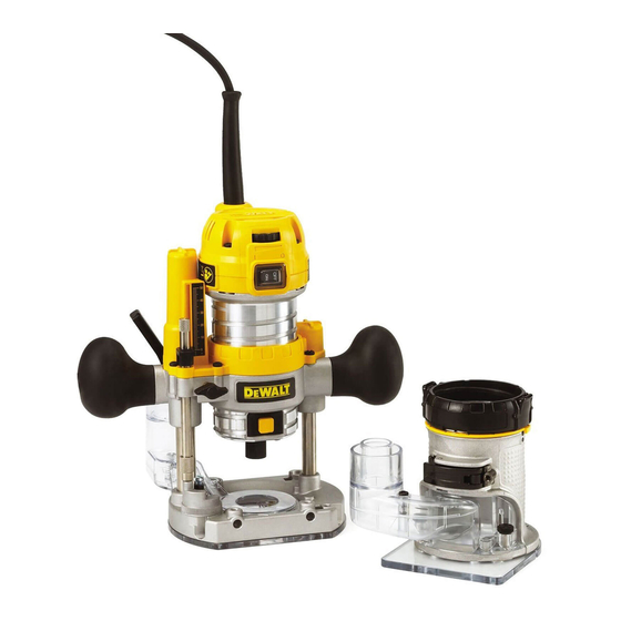
Summary of Contents for DeWalt D26204-XE
- Page 1 INSTRUCTION MANUAL D26204-XE HEAVY-DUTY COMPACT ROUTER...
-
Page 3: Technical Data
Technical Data accessories or poorly maintained, the vibration emission may differ. This may significantly increase the exposure level over the total working period. D26204-XE An estimation of the level of exposure to vibration should also take into account Voltage the times when the tool is switched off or when it is running but not actually doing Power input the job. - Page 4 e) When operating a power tool outdoors, use an extension cord suitable WARNING: To reduce the risk of injury, user must read the instruction manual. for outdoor use. Use of a cord suitable for outdoor use reduces the risk of electric shock.
- Page 5 b) Do not use the power tool if the switch does not turn it on and off. Any – This appliance is not intended for use by persons (including children) with reduced physical, sensory or mental capabilities, or lack of experience and power tool that cannot be controlled with the switch is dangerous and must knowledge, unless they have been given supervision or instruction concerning be repaired.
- Page 6 • Be sure that the motor has stopped completely before you lay the router • Hearing protection: AS/NZS1270 Acoustics – Hearing Protection; down. If the cutter head is still spinning when the tool is laid down, it could cause • Respiratory protection: AS/NZS1716 Respiratory Protective Devices. injury or damage.
- Page 7 FIG. 1 PLUNGE BASE FIXED BASE D-SUBBASE ROUND SUBBASE...
- Page 8 ASSEMBLY AND ADJUSTMENTS ....Class II Construction .....earthing terminal ....(double insulated) ....safety alert symbol WARNING: To reduce the risk of serious personal injury, turn tool off and disconnect tool from power source before making any adjustments or removing/ …/min ..per minute BPM ..beats per minute installing attachments or accessories.
- Page 9 Cutter Installation and Removal (Fig. 1, 3) TO REMOVE THE CUTTER 1. Remove the motor unit from the base unit. Refer to Motor Quick Release. WARNING: To reduce the risk of injury, turn unit off and disconnect it from 2. Depress the spindle lock button (E) to hold the spindle shaft in place while power source before installing and removing accessories, before adjusting or turning the collet nut (L) counterclockwise with the wrench provided.
- Page 10 FIXED BASE ASSEMBLED Excessive force should not be used to clamp the locking lever. Using excessive force may damage the fixed base. Proper hand position requires one hand to be wrapped around the base as shown. When the locking lever (I) is clamped the motor (J) should not move in the fixed base. WITH PLUNGE BASE ASSEMBLED Adjustment is needed if the locking lever will not clamp without excessive force or if Proper hand position when using the plunge base requires one hand on each of the...
- Page 11 5. While holding down on the cone, tighten the subbase screws. TO USE TEMPLATE GUIDES 1. Install template guide to subbase using two screws and tighten securely. FIG. 6A 2. Center the subbase. Refer to Centering the Subbase. Adjusting the Depth of Cut (Fixed Base Only, Fig. 1, 7) WARNING: To reduce the risk of injury, turn unit off and disconnect it from power source before installing and removing accessories, before adjusting or when making repairs.
- Page 12 3. Tighten the thumb screws (NN). 4. Slide the parallel fence (GG) over A basic parallel fence is included with the D26204-XE and works with the fixed base. the rods. The basic parallel fence D262003-XJ is available as an accessory for the other models and may be purchased from your local retailer or service center at extra cost.
- Page 13 4. When using vacuum attachment, be aware of the placement of the vacuum FIG. 9 cleaner. Be sure that the vacuum cleaner is stable and that its hose will not interfere with the work. Vacuum Attachment (Plunge Base Only, Fig. 10) 1.
- Page 14 Set-up: Plunge Base 6. Grasping the top, knurled section of the depth adjustment rod (O), slide it up so that the tab (EE) aligns with the desired depth of cut on the depth adjustment INSERTING THE MOTOR INTO THE PLUNGE BASE (FIG. 1, 11) scale (DD).
- Page 15 Operation: All Bases FINE ADJUSTMENT OF ROUTING DEPTH (FIG. 12) WARNING: To reduce the risk of injury, turn unit off and disconnect it from DIRECTION OF FEED (FIG. 13) power source before installing and removing accessories, before adjusting or The direction of feed is very important when routing and can make the difference when making repairs.
- Page 16 VARIABLE SPEED CONTROL (FIG. 1) At approximately 100 hours of use, take or send your tool to your nearest D WALT factory service center or D WALT authorised service center to be thoroughly cleaned and This router is equipped with a variable speed dial (C) with an infinite number of inspected.
- Page 17 ACCESSORIES WARNING: Since accessories, other than those offered by D WALT, have not been tested with this product, use of such accessories with this tool could be hazardous. To reduce the risk of injury, only D WALT recommended accessories should be used with this product.
- Page 20 82 Taryn Drive, Epping, VIC 3076 Australia • 1800 444 224 (Aust) or 0800 339 258 (NZ) www.dewalt.com.au • www.dewalt.co.nz (NOV13) Part No. N377513 D26204-XE Copyright © 2012, 2013 D WALT The following are trademarks for one or more D WALT power tools: the yellow and black color scheme;...


