Advertisement
Quick Links
Advertisement

Related Manuals for Extreme Flight 50cc Extra 300 ARF


Summary of Contents for Extreme Flight 50cc Extra 300 ARF
-
Page 1: Instruction Manual
50cc Extra 300 ARF Instruction Manual ©Copyright 2007 Extreme Flight RC, Ltd. - Page 2 THIS IS NOT A TOY! Serious injury, destruction of property, or even death may result from the misuse of this product. Extreme Flight RC is providing you, the buyer with a very high quality model aircraft component kit, from which you, the buyer, will assemble a flying model.
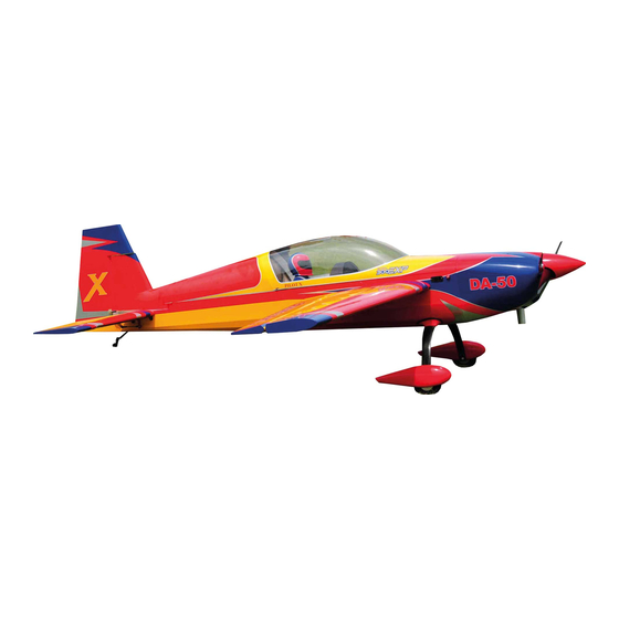
- Page 3 Congratulations on your purchase of the Extreme Flight RC 50cc Extra 300 ARF! Like our previous 50cc Yak-54 release, the Extra is among the largest aircraft currently available for 50cc gas engine power. Its light weight yet robust construction allows the Extra to perform...
- Page 4 A few tips to ensure success and airframe longevity 1. We are very pleased with the level of craftsmanship displayed by the builders in our factory. Through many grueling test flights containing maneuvers that no aircraft should be subjected to, our prototypes have remained rigid and completely airworthy.
- Page 5 Hardware Your new Extreme Flight 50cc Extra 300 includes all necessary hardware with the exception of main wheels, tailwheel, axles and collars and a 4” spinner. These items were omitted as I have been unable to source satisfactory versions of these items in China.
-
Page 6: Elevator Assembly
Elevator Assembly 1. Locate the horizontal stabilizer/elevator assemblies as well as the composite control horns and base pieces from the elevator hardware package. 2. Use a sharp #11 blade to remove the covering over the pre-cut control horn slots near the bottom leading edge of the elevator. Cut the covering 1/16”... - Page 7 3. Insert the 2 control horns into the base plate and trial fit the horns into the slot and make sure they seat properly against the base and elevator surface. You may need to remove 1/16” from the front of the base plate to prevent it from overhanging the bevel. Remove the horn assembly and scuff the portion of the horns that will be inserted into the elevator with sandpaper.
- Page 8 4. Use a sharp #11 blade to remove the covering from the slot for the elevator servo control horn. You may have to slightly enlarge this hole to allow for maximum travel. 5. Before installing the elevator servos, I highly recommend that you take a moment and wick some thin CA (I prefer the Mercury Adhesives line of CAs) around the servo mounting rib and root rib where they attach to the sheeting as well as the anti-rotation pin...
- Page 10 6. Use the manufacturer supplied mounting hardware and install the elevator servo with the output shaft toward the front of the stab. Feed the servo wire out of the hole in front of the servo and out of the root rib. You will need to attach a 36” servo extension to the servo lead to reach the receiver in the radio compartment.
- Page 11 about a ¼” from its final position and use a paper towel to remove the excess epoxy that has been forced from the hole. Push the hinge the rest of the way in and make sure the hinge pin is centered in the hinge line.
- Page 12 you will ensure a smooth operating surface with no binding. Seal the bottom of the hinge gap with a strip of Ultracote or Blenderm tape. Be sure to fully deflect the control surface when applying the tape or Ultracote to allow full deflection once the gap is sealed. 10.
-
Page 13: Wing Assembly
moment with your covering iron and go over all of the seams with a medium heat setting, paying special attention to the ends of thin trim stripes. At this point clean the 2 elevator/stab assemblies with Windex and a soft cloth and put them away in their protective bag. Wing Assembly 13. - Page 14 linkage. Aileron servo arm length should be 1.50”. We use and recommend the SWB double lock aluminum arms. As always, use blue Loctite on ALL bolts! 16. Before beginning the next assembly process, take a few minutes with your sealing iron on a medium heat setting and go over all seams, paying special attention to thin trim stripes and the seam at the leading edge of the wing.
- Page 15 Rudder and tailwheel assembly and mounting 17. Locate the rudder, the rudder control horns and the 2 slotted base plates. Use a sharp #11 blade to remove the covering from the 2 pre-cut slots in the rudder. 18. Trial fit the 2 servo horns through the base plate and into their proper position flush against the rudder surface.
- Page 16 24. Locate a 2mm ball link from the hardware bag. Remove the covering from the hole on the bottom of the rudder. 25. Scuff the shaft of the ball link with coarse sandpaper. Mix up a small amount of 5 minute epoxy and apply it to the ball link and the hole in the bottom of the rudder.
- Page 17 26. While this dries let’s prepare the tailwheel assembly and get it mounted. First disassemble the tailwheel assembly as shown. 27. Use a rotary tool with a grinding bit or a small file to create a flat spot on the tailwheel wire for the set screws in the aluminum fittings to seat against.
- Page 18 27. Position the tailwheel assembly on the rear bottom of the fuselage and be sure the tailwheel wire is aligned with the rudder hinge line. Secure the tailwheel with a couple of pieces of masking tape while you drill 2 holes with a 1/16” drill bit. Apply a few drops of thin CA to the holes and allow to dry then secure the assembly to the bottom of the fuselage as shown with the 2 provided coarse thread wood screws and 2 washers.
-
Page 20: Fuselage Assembly
Fuselage Assembly 28. We’ll begin by installing the landing gear. Locate the aluminum main landing gear, the landing gear slot cover 4 4mm bolts, lock nuts and washers. Insert the gear into the slot on the bottom of the fuselage and center it in the slot. Use the pre-drilled holes in the aluminum gear as guides and mark the location of the holes with a pencil. - Page 21 wood mounting plate and aluminum gear mount. Secure with the 4mm nylon insert lock nuts.
- Page 22 31. Locate the 2 fiberglass landing gear fairing and the black neoprene tubing. Use a sharp hobby blade and cut through one wall of the tubing horizontally along the length of the tubing. Press the tubing onto the edges of the fairing as shown and secure with thin CA. Make sure the seam is on the rear side of the fairing.
- Page 23 32. Slide the fairings over the landing gear and against the sides of the fuselage. You may need to open the hole in the fairing slightly with a rotary tool bit for proper fit. Use a pencil to mark the location of the bottom of the fairing on the landing gear and then remove the fairing.
- Page 24 34. Slide the fairing back into place and apply masking tape to keep it in position while the glue dries. 35. Locate the 2 wheel pants and 2 plywood mounting plates. Use sandpaper to scuff the inside of the pant for better glue adhesion. Glue the ply mounting plate centered in the opening of the pant as shown with 30 minute epoxy.
- Page 25 36. Install your choice of axles and wheels. Use a rotary tool to open a slot in the wheel pant to allow it to slide over the axles. Position as desired and mark the location for the blind nuts using the pre- drilled holes in the aluminum gear as a guide.
- Page 27 37. While the Extra is still upside down let’s install the rudder and finish up the tailwheel installation. Apply 30 minute epoxy to the holes in the rudder post and to the rudder hinges. As you position the rudder onto the vertical fin, be sure the tailwheel tiller arm is inserted into the ball link.
- Page 28 38. Next let’s install the engine. We have made this process very easy. The center and offset marks have been scribed into the front of the firewall with a laser. Most manufacturers will provide a mounting template for their engines. Templates for the DA-50 and Brillelli 60 are available for download from our website.
- Page 29 40. Now let’s set up the throttle linkage. If you are using a DA-50 this is very easy. You may need to rotate the carburetor on the DA-50 180 degrees so that the throttle arm is facing the bottom. Please contact DA for the proper procedure.
- Page 30 42. Here is where we installed our fuel dot and ignition switch. The radio switch is installed in the same location on the opposite side of the fuselage. 43. Once all plumbing is completed and throttle servo and linkage is installed glue the top of the motor box in place with 30 minute epoxy.
- Page 31 44. If you are planning to use a tuned pipe or canister now is the time to install it.. You will need to remove the covering from the bottom of the fuselage as pictured. Seal the edges of the covering to the edges of the pipe tunnel and paint a thin coat of alcohol thinned epoxy to seal the wood in the tunnel.
- Page 32 46. Install your rudder servo using the supplied hardware with the output shaft toward the front of the plane. Depending on the servo used you may need to lightly sand the sides of the mount to accept your choice of servo. We recommend the use of one of the new “mega-torque”...
- Page 33 48. Assemble one end of the linkage by inserting the pull-pull cable into a crimp, through the hole in the brass pull-pull fitting and back through the crimp. Loop the cable back through the crimp a second time and crimp with side cutters. 49.
- Page 34 50. Now let’s mount the cowl. It will be necessary to open the bottom of the cowl for the engine cylinder to clear. Use a rotary tool to open the bottom of the cowl. The following picture depicts the typical opening for a DA-50. This will require further work to allow clearance for the spark plug wire and muffler but should allow you to slide the cowl into position for mounting.
- Page 35 52. Peel the tape back just behind the F1 former and place the cowl into position, flush with the rear of the F1 former. Place your spinner (4”) on the engine to aid with alignment. View the cowl from several angles to insure that is positioned properly. When satisfied put the four tape strips back into position and drill a 1/8”...
- Page 36 53. Remove the cowl and soak the cowl mounting tabs with thin CA. Install the 4 4-40 blind nuts into the cowl mounting tabs. The cowl is attached using 4 4-40 socket head bolts in conjunction with 4 bonded sealing washers as shown.
- Page 37 54. Now let’s install the stab/elevators. Open the holes in the rear side of the fuselage to expose the pre-mounted 3mm blind nuts. You will also need to open a hole for the servo leads to pass through. Slide the stab halves onto the carbon fiber stab tube and secure with a 3mm bolt and washer inserted through each mounting tab and into the pre-mounted blind nuts.
- Page 38 This completes the assembly of the 50cc Extra 300. As a final step clean the entire aircraft with glass cleaner, then apply a coat of spray-on wax and buff the finish to a high gloss. My favorite product for this is Eagle One Wet Wax AS-U-DRY, available in the automotive section of most Wal-Marts, K-marts, Sears, Targets, etc.
-
Page 39: Control Surface Throws
80-90% exponential. Again, this is just a starting point. Adjust to your liking. Thanks again for your purchase of the Extreme Flight RC 50cc Extra 300 ARF. I hope you enjoy assembling and flying yours as much as I have mine.
Need help?
Do you have a question about the 50cc Extra 300 ARF and is the answer not in the manual?
Questions and answers