Table of Contents
Advertisement
Advertisement
Table of Contents

Related Manuals for Korg Synthesizer/Vocoder microKORG


Summary of Contents for Korg Synthesizer/Vocoder microKORG
-
Page 3: Precautions
Be careful not to let metal objects get into the equipment. If something does slip into the equipment, unplug the AC adapter from the wall outlet. Then contact your nearest Korg dealer or the store where the equipment was purchased. -
Page 4: Table Of Contents
Thank you for purchasing the Korg vocoder. To ensure trouble-free enjoyment, please read this manual carefully and use the product correctly. Precautions ...iii Data handling ...iii Printing conventions in this manual ...iii Introduction ... 1 Explains the features of the microKORG, and the names and functions of each part. - Page 5 Table of Contents 1. VOICE — SYNTH/VOCODER ... 2. PITCH — SYNTH/VOCODER ... 3. OSC1 (Oscillator 1) — SYNTH/VOCODER ... 4. OSC2 (Oscillator 2) — SYNTH ... 5. MIXER — SYNTH ... 6. FILTER — SYNTH ... 7. FILTER EG —...
- Page 6 Table of Contents Using the microKORG with other MIDI devices (MIDI).. 48 Explains how to make connections with other MIDI devices, and explains the function of the MIDI parameters adjusted by edit control knobs 1–5 for the corresponding setting of the EDIT SELECT 1/2 knobs. MIDI on the microKORG ...
-
Page 7: Introduction
Introduction 1. Analog modeling synthesizer The analog modeling system of the microKORG uses DSP technology to simulate an analog synthesizer. Starting with a variety of different oscillator algorithms (such as the sawtooth and square waves familiar to users of analog synthesizers) you can use the various controls located on the front panel to edit any sound, or to create sounds of your own. -
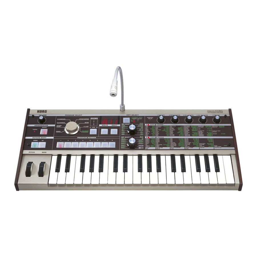
Page 8: Front And Rear Panel
Front and rear panel Front panel BANK SELECT dial Items on the front panel that relate Selects the program bank. to the Vocoder are printed in green. VOLUME knob Adjusts the volume of the output from the OUTPUT jacks (L/MONO, R) and headphone jack. - Page 9 Front and rear panel TIMBRE SELECT/FORMANT HOLD key ORIGINAL VALUE LED If a Synth program using "layer" is selected, This will light if the value of the parameter this key allows you to chose which timbre currently being edited matches the value that is will be edited or sounded, or lets you edit stored in the program.
-
Page 10: Rear Panel
Front and rear panel Rear panel AUDIO IN 2 A Synth program can use an audio signal from an external device connected here as the oscillator 1 waveform. A Vocoder program uses this input signal as the external carrier for the vocoder. LINE jack VOLUME 2 knob Connect a synthesizer... -
Page 11: Preparations
Preparations The diagram below shows basic connections for the microKORG. Make substitu- tions as appropriate for your equipment. MIDI OUT MIDI IN E M - 1 AC adapter (included) Connect to an AC outlet MIDI keyboard, tone generator module, rhythm machine etc. Be sure to turn off the power of all devices before making connections. -
Page 12: Turning The Power On
Turning the power on 1. The power supply Before you connect the power supply, make sure that the power switch is turned off (i.e., in the outward position). Connecting the AC adaptor Firmly insert the plug of the included AC adaptor into the jack. Then connect the AC adaptor to an AC outlet. -
Page 13: Quick Start
Quick Start Listening to the demo songs The microKORG contains several demo songs. Here's how to listen to the demo songs and hear the sounds of the microKORG. Hold down the SHIFT key and press the ARPEGGIATOR ON/OFF The demo will begin playing. The SHIFT , OCTAVE SHIFT DOWN , UP , and PROGRAM NUMBER key LEDs will light. -
Page 14: Synth Programs
Synth programs 1. Selecting and playing a program The microKORG contains 128 programs that you can select and play immediately. Programs are arranged in Banks. Each bank contains two “Sides”, and each side contains eight programs. To select different programs, use the front panel PRO- GRAM SELECT knob and PROGRAM NUMBER keys. - Page 15 Synth programs In the case of a LPF (Low Pass Filter) Knob 2: RESONANCE Adjusts the resonance of the filter. This adds a distinctive character to the sound. Cutoff Cutoff Low resonance value Knob 3: EG ATTACK (FILTER EG + AMP EG ATTACK) Adjusts the attack time of the filter EG and amp EG.
-
Page 16: Vocoder Programs
Vocoder programs 1. Playing a vocoder program Here's how to connect the included mic and play a vocoder program. A vocoder applies the spectral character of an externally-input voice (the "modula- tor") to an oscillator or other sound (the "carrier"), and outputs the result. In the most popular use of a vocoder, you can speak or sing into a mic and play chords on the keyboard, to create the impression that an instrument is speaking or singing. -
Page 17: Arpeggiator
Arpeggiator Using the arpeggiator The arpeggiator is a function that automatically arpeggiates the notes of a chord you play; i.e., sounds the notes one after the other. The microKORG's arpeggiator provides six types of arpeggio pattern, and lets you adjust the duration (gate time) of the notes that are sounded. -
Page 18: Editing
Editing Basic editing procedure All of the editable parameters are organized into "sections". Each section contains up to five parameters, which are controlled using the edit control knobs 1 – 5. The two knobs labelled EDIT SELECT 1 and EDIT SELECT 2 are used to select a section. - Page 19 Basic editing If you select another program or turn the power off before you write, your edits will be lost. If the parameter value does not change when you turn knobs 1–5 When you use EDIT SELECT 1 or EDIT SELECT 2 to select a section and turn knobs 1–5 to edit the parameter values, the value in the display will sometimes continue blinking, and the parameter value will not change.
-
Page 20: Editing Each Timbre
Basic editing Editing each timbre Synth programs can have up to two timbres. A timbre consists of the parameters of EDIT SELECT 1 VOICE (except for "SYNTH/VOCODER" and "SINGLE/LAYER") through LFO2 sections, and the parameters of EDIT SELECT 2 PATCH 1–4 sections. The VOICE section parameters "SYNTH/VOCODER"... -
Page 21: Editing A Synth Program
Editing a synth program Overview The three attributes of sound: pitch, tone, and volume Sound has three basic attributes; pitch, tone, and volume. To control these attributes, the microKORG analog modeling synthesizer provides "oscillator," "filter," and "amp (amplifier)" sections, just as on the analog synthesiz- ers of the past. -
Page 22: Voice - Synth/Vocoder
1. VOICE These settings determine the basic character of the program, and how it will sound. "SYNTH/VOCODER" (knob 1) specifies whether the program will be a synth program or a vocoder program. If you want this to be a synth program, select Synthesizer ( program. -
Page 23: Pitch - Synth/Vocoder
2. PITCH These settings specify the pitch of the oscillator. Use "TRANSPOSE" (knob 1) and "TUNE" (knob 2) to set the desired pitch. These settings are shared by oscillators 1 and 2. In this section you can also set the portamento time, and specify how the PITCH and MOD wheels will affect the pitch. TRANSPOSE [-24...24] TUNE... - Page 24 3. OSC1 The oscillator generates the waveform that is the basis of the sound. The timbre has two oscillators. The settings in this section are for oscillator 1. "WAVE" (knob 1) selects the basic waveform for oscillator 1, and "CONTROL 1" (knob 2) and "CONTROL 2" (knob 3) modify the waveform. For example if you set "WAVE" to Saw ( "CONTROL 1"...
- Page 25 3. OSC1 WAVE CONTROL 1 Triangle Wave ( CONTROL 1 You can modify the waveform by This is a triangle wave, which has adjusting this value. weaker overtones and a stronger A setting of 0 will produce a triangle fundamental than a sawtooth wave wave, and a setting of 127 will pro- or square wave.
- Page 26 [1...64]: Selects the DWGS waveform. ( Table 3-1) – – – DWGS waveform data was first used in the Korg DW-6000 (which went on sale in 1984), and has continued to be devel- oped since that time. [0...127]: CONTROL 2 [0...127]:...
- Page 27 3. OSC1 WAVE CONTROL 1 CONTROL 1 Audio In ( The waveform of the audio signal This adjusts the volume balance input from the AUDIO IN 1 or 2 between AUDIO IN 1 and AUDIO jacks will be used instead of an os- IN 2.
-
Page 28: Osc2 (Oscillator 2) - Synth
4. OSC2 Here you can make settings for oscillator 2. You can create a variety of sounds by using two oscillators together. For example you can adjust "SEMITONE" (knob 3) and "TUNE (knob 4) so that one oscillator acts as though it were part of the overtone structure of the other oscillator, set the pitches of the two oscillators to an interval of harmony, or set both oscillators to the same pitch but slightly detune one of them to create a detuning effect. -
Page 29: Mixer - Synth
5. MIXER These parameters adjust the volume balance of the oscillator 1 and 2, and the noise generator. "OSC 1 LEVEL" (knob 1) sets the output level of oscillator 1, "OSC 2 LEVEL" (knob 2) sets the output level of oscillator 2, and "NOISE LEVEL"... -
Page 30: Filter - Synth
6. FILTER The filter controls the tonal character of the sound produced by the oscillator. It determines the tone by allowing only the desired portion of the sound to pass. "TYPE" (knob 1) selects the type of filter (i.e., the way in which it will cut the frequency). "CUTOFF" (knob 2) sets the frequency at which the cut will occur. - Page 31 6. FILTER TYPE -12dB BPF ( -12dB/oct BPF (Band Pass Filter) allows a frequency band in the re- gion of the cutoff frequency to pass, and cuts the remaining frequencies. Figure 6-2 It is used when you wish to empha- BPF (Band Pass Filter) size only a specific portion of the frequency range.( Figure 6-2)
-
Page 32: Filter Eg - Synth
7. FILTER EG Here you can make settings for the filter EG, which applies time-variant change to the tone ( Figure 7-1). Make these settings to specify the "shape" of the EG, and use the FILTER parameter "FILTER EG INT" to specify the amount of effect that the EG will have ( p.24). By making FILTER EG settings, you can make the tone change as time passes. -
Page 33: Amp - Synth
8. AMP (Amplifier) These parameters specify the volume. The sound that is created by passing through the oscillator and filter is amplified by the amp. "LEVEL" (knob 1) adjusts the volume. "KBD TRACK" (knob 4) adjusts how keyboard tracking will affect the volume, and "DISTORTION" (knob 3) specifies whether the sound will be distorted. -
Page 34: Amp Eg - Synth/Vocoder
9. AMP EG Here you can make settings for the AMP EG, which applies time-variant change to the volume ( Figure 9-1). By making AMP EG settings, you can make the volume change as time passes. Create the desired volume curve by adjusting the ADSR parameters; ATTACK (knob 1), DECAY (knob 2), SUSTAIN (knob 3), RELEASE (knob 4). -
Page 35: Synth/Vocoder
10. LFO 1, 11. LFO 2 The timbre has two LFOs (Low Frequency Oscillator). The cyclic change produced by an LFO can modulate various aspects of the sound such as the pitch, tone, or volume. Use "WAVE" (knob 1) to select the LFO waveform, knob 2 to select the key sync method, "TEMPO SYNC" (knob 3) to synchronize the LFO cycle to the tempo, and "FREQUENCY"/"SYNC NOTE"... -
Page 36: Synth
(oscillator, filter, amp, EG, LFO, and other controllers) was connected ("patched") by a patch cord as desired, allowing you a great deal of freedom in creating the sound. The Korg MS-20 (which went on sale in 1978) also allowed a limited degree of this type of patching. -
Page 37: Editing A Vocoder Program
Editing a vocoder program Overview A vocoder is a device that analyzes the character (the frequency response of each band) of a "modulator" signal (typically a human voice from a mic), and applies a filter with the analyzed characteristics to the "carrier" signal (typically a waveform produced by an oscillator), imposing a vocal character on that waveform, and making it seem as though the instrument is talking. -
Page 38: Osc1 - Synth/Vocoder
1. VOICE The "1. VOICE" parameters are the same as for a synth program with a "SINGLE/LAYER" setting of Single ( p.16). To use the program as a vocoder program, set "SYNTH/VOCODER" (knob 1) to Vocoder ( 2. PITCH The "2. PITCH" parameters are the same as for a synth program ( p.17). They specify the pitch of the carrier. 3. -
Page 39: Vocoder
4. AUDIO IN 1 These parameters adjust the input from AUDIO IN 1 (the modulator). Adjust "THRESHOLD" (knob 2) so that noise is not heard when you are not speaking, and adjust "GATE SENSE" (knob 1) so that the vocoder sound is not cut off unnaturally. Use "HPF LEVEL" (knob 3) to emphasize the consonants (such as "s" sounds) of the input voice. GATE SENSE [0...127] THRESHOLD... -
Page 40: Mixer - Vocoder
5. MIXER This sets the output level of the carrier. The level you specify here will be the input level to the band-pass filter (Synthesis Filter) of the carrier. OSC 1 LEVEL [0...127] INST LEVEL Specifies the output level of Oscil- Specifies the output level of the sig- lator 1 (carrier). -
Page 41: Filter - Vocoder
6. FILTER By using "FORMANT SHIFT" (knob 1) and "CUTOFF" (knob 2) to shift the cutoff frequency of each band pass filter of the carrier (the "synthesis filter"), you can raise or lower the frequency response while maintaining the character of the modulator, thus varying the character of the vocoder output. -
Page 42: Mod Wheel
7. FC MOD These parameters select the modulation source that will vary the cutoff frequency of the carrier band-pass filter (the synthesis filter), and specify the depth of the modulation. For example if you set the modulation source "SOURCE" (knob 1) to AMP EG (A.EG) and use "INTEN- SITY"... -
Page 43: Amp - Vocoder
8. AMP These parameters adjust the volume. "LEVEL" (knob 1) specifies the volume of the internal sound source (OSC 1, NOISE) for the carrier. "KBD TRACK" (knob 4) specifies how keyboard tracking will affect the volume, and "DISTORTION" (knob 3) specifies whether the sound will be distorted. -
Page 44: Ch Level A, 13. Ch Level B
12. CH LEVEL A, 13. CH LEVEL B These parameters set the level for each of the eight band-pass filter channels (SYNTHESIS FILTER) of the carrier ( p.35). This lets you adjust the output level of the internal carrier sound source (OSC 1, NOISE). If desired, you can initialize (127) the level of all band-pass filter channels in a single step. -
Page 45: Editing The Effects And Eq
The microKORG's effect structure Editing the effects and EQ Overview The output from the amp section of a synth program or vocoder program is sent to the modulation effect (MOD FX) delay effect (DELAY FX) equalizer (EQ). ( p.15 Figure 0-1, ›p.31 Figure v0-1) You can edit the modulation type effect and the delay effect to create the desired sound in the same way as when editing the filter or amp parameters. -
Page 46: Mod Fx - Synth/Vocoder
16. MOD FX The modulation effect applies various types of cyclic change to the original sound. You can use it to give the sound greater depth, or to produce the impression that multiple sound sources are being heard simultaneously. You can also use LFO modulation to simulate cyclic changes produced by a performer on an instrument, such as breathing on a wind instrument or the strings of a string instrument. -
Page 47: Delay - Synth/Vocoder
17. DELAY The delay effect simulates the delays that occur when sound travels through air. "TYPE" (knob 1 ) selects the type of delay effect. "DELAY DEPTH" (knob 4 ) sets the delay depth and the amount of feedback. "TEMPO SYNC" (knob 2 ) specifies whether the delay time will be synchronized to the tempo set by the arpeggiator or by an external MIDI clock. - Page 48 18. EQ This is a two-band equalizer. Use EQ FREQ (knobs 1 and 3 to specify the frequency that you want to adjust, and use knobs 2 and 4 to adjust the gain of each frequency band. Excessively raising the equalizer gain parameters may cause the output to be distorted. LOW EQ FREQ.
-
Page 49: Editing The Arpeggiator
The structure of arpeggiator Editing the arpeggiator Overview The microKORG's arpeggiator provides six arpeggio types. You can adjust the duration (gate time) and spacing of the notes played by the arpeggiator. The arpeggiator settings are adjusted by the ARPEG.A and ARPEG.B parameters. Each of the up to eight steps produced by the ARPEG.A and ARPEG.B settings can be switched on/off using the "step arpeggiator,"... -
Page 50: Arpeg. A - Synth/Vocoder
19. ARPEG. A Here you can make various arpeggio-related settings. "TYPE" (knob 4 ) selects the arpeggio type. "TEMPO" sets the tempo of the arpeggiator, and "RESOLUTION" (knob 2 ) specifies the spacing of the notes relative to the tempo. "GATE (knob 3 ) sets the duration of the arpeggiated notes, and "RANGE"... -
Page 51: Arpeg. B - Synth/Vocoder
20. ARPEG. B Here you can make additional arpeggio-related settings. "LAST STEP" (knob 4 ) sets the number of steps in the arpeggio. "LATCH" (knob 1 ) specifies how the arpeggiator will operate when you release the keyboard, "SWING" (knob 2 ) adjusts the sense of swing, and "KEY SYNC" (knob 3 ) specifies how the arpeggiator will be synchronized to the keyboard. -
Page 52: Overall Settings (Global)
GLOBAL structure Overall settings (GLOBAL) Overview The GLOBAL section lets you can make overall settings for the microKORG. For example, although it is possible to individually adjust the pitch of each synth or vocoder program, you can use the GLOBAL pitch settings ("MASTER TUNE" and "MASTER TRANSPOSE") to adjust the pitch of all programs. -
Page 53: Overall Settings
Specifies the internal MIDI IN/ playing dynamics) will affect vol- OUT routing within the micro- ume and tone. KORG. This setting will affect the Use the setting that is appropriate way in which MIDI data is trans- for your situation. -
Page 54: Controlling Midi
Using the microKORG with other MIDI devices (MIDI) Overview Here you can make MIDI-related settings for the microKORG. MIDI stands for Musical Instrument Digital Interface, and is a world-wide standard for exchanging various types of musical data between electronic musical instru- ments and computers. -
Page 55: Midi-Related Settings After Connection
MIDI on the microKORG Connecting an external MIDI sequencer or computer etc. You can play the microKORG's keyboard and record your performance on an external MIDI sequencer/computer (connected via a MIDI interface), and then play back the recorded performance to sound the microKORG's tone generator (i.e., using the microKORG as an input keyboard and MIDI tone generator). -
Page 56: Synchronizing The Arpeggiator
MIDI on the microKORG a second time. To prevent each note from being sounded twice, once directly from the keyboard and once from the echoed-back note, you must turn the microKORG's Local Control setting off. Recording the MIDI output from the microKORG's arpeggiator onto an external MIDI sequencer or computer Connect the microKORG's MIDI OUT connector to the MIDI IN connector of your external MIDI sequencer / computer, and connect the microKORG's MIDI IN... -
Page 57: Midi
22. MIDI Here you can make MIDI-related settings for the microKORG. MIDI CH [1...16] LOCAL Specifies the MIDI channel. Switch the local on/off setting. When you wish to transmit pro- OFF ( gram changes or system exclusive With this setting, controllers such as messages via MIDI, set the global the keyboard and modulation MIDI channel to match the MIDI... -
Page 58: Messages Transmitted And Received By The Microkorg
Messages transmitted and received by the microKORG MIDI channels MIDI uses sixteen channels (1-16). MIDI messages can be transmitted and received when the channel of the receiving device matches the channel of the transmitting device. MIDI messages such as note-on/off and pitch bend are transmitted and received on the MIDI channel specified by the MIDI "MIDI CH"... -
Page 59: Parameters Transmitted And Received Via Nrpn
Messages transmitted and received by the microKORG • Modulation depth (CC#01) [Bn, 01, vv] When a modulation depth message is received, the LFO2 vibrato depth will change according to the value specified for PITCH "VIBRATO INT." If the value of the received message is the maximum value (127), vibrato will be applied over the full pitch range specified by "VIBRATO INT."... - Page 60 Messages transmitted and received by the microKORG MSB (Hex) LSB (Hex) Value (transmitted) ON/OFF 00(00) 02(02) 0: OFF, 127: ON RANGE 00(00) 03(03) 0: 1 Octave, 1: 2 Octave, 2: 3 Octave, 3: 4 Octave LATCH 00(00) 04(04) 0: OFF, 127: ON TYPE 00(00) 07(07) 0: Up, 26: Down, 51: Alt1, 77: Alt2, 102: Random, 127: Trigger 0...21: Up, 22...42: Down, 43...63: Alt1, 64...85: Alt2, 86...106: Random, 107...127: Trigger GATE...
-
Page 61: System Exclusive Messages
), data dumps can not be received. If you wish to obtain the "MIDI Implementation" which includes details of the MIDI exclusive format, please contact a Korg dealer. The microKORG maintains data compatibility only for parameters that it shares with the MS2000/MS2000R. -
Page 62: Front Panel Knob/Key Control Change Assignments
Messages transmitted and received by the microKORG Front panel knob/key control change PITCH Portamento assignments Wave Control changes can be assigned to OSC 1 Control1 each front panel knob/key of the Control2 microKORG so that the changes in Wave sound as controlled by knob/key OSC Mod operations can be transmitted as OSC 2... - Page 63 Messages transmitted and received by the microKORG Control 2 values when OSC 1 Wave = DWGS When the synth parameter OSC 1 "WAVE" is set to DWGS, the "CONTROL 2" (knob 3 ) will select the DWGS waveform. The value of the control change transmitted/received by operating the "CONTROL 2"...
-
Page 64: Saving Data
Saving Data Saving a program Use the PROGRAM SELECT BANK Settings that will be saved SIDE key, the PROGRAM SELECT • All parameters VOICE–ARPEG.B dial, and the PROGRAM NUMBER (FORMANT HOLD key on/off) keys to select the program number • ARPEGGIATOR ON/OFF key where you want to save the current •... -
Page 65: Shift Functions
SHIFT functions 1-1. COPY TIMBRE ( Copying a timbre Turn knob 1 to select the copy-source You can access this function only if a program (A.11–B.88). synth program is selected. The 1 key will begin blinking. Timbre settings from another program If you decide to cancel this operation, will be copied to the timbre of the press the lit SHIFT key. -
Page 66: Initializing Ch Level And Ch Pan
Initializing CH LEVEL and CH PAN 1-2. INIT LEVEL ( 2-2. INIT PAN ( Initializing CH LEVEL A/B Initializing CH PAN A/B You can access this function if a vocoder You can access this function if a vocoder program is selected. program is selected. -
Page 67: Assigning Control Changes
Assigning control changes 5-1. CONTROL CHANGE ( Assigning control changes SELECT 2 dial to select the section that You can assign control change numbers to contains the parameter whose control the principal parameters accessed by the change you want to specify. EDIT SELECT 1 and 2 knobs and knobs Turn each knob to select the desired 1–5. -
Page 68: Data Dump
Data dump 6-1. MIDI DATA DUMP ( Data dump Turn the 1 knob to select the type of "Data dump" is a function that transmits data dump that will be transmitted. program or global data in the form of 1Program ( MIDI exclusive data, so that it can be Data for the currently selected program saved on a connected MIDI data filer or... -
Page 69: Restoring The Factory Settings
Restoring the factory settings 7-1. PRELOAD ( Restoring the factory settings condition. This operation restores the microKORG's 1Program ( programs and global data settings to the Load only data for one program. factory-set condition. The factory-set Program ( settings are referred to as the "preload Load data for all programs (128 data."... -
Page 70: Timbre Solo/Switch Edit Select
Other SHIFT key functions TIMBRE SOLO INC/DEC PARAM VALUE Timbre solo function Increment or decrement the parameter • Hold down the SHIFT key and press value the TIMBRE SELECT key. RETURN PARAM VALUE (Compare) If a Layer synth program is selected, only one timbre will sound. -
Page 71: Appendix
Appendix Synchronizing the LFO 1/2 rate or the delay time of the delay effect to the arpeggiator tempo You can synchronize the LFO 1/2 rate or the delay time of the delay effect to the arpeggiator tempo. (When "TEMPO SYNC"=ON) Example 1. -
Page 72: Troubleshooting
Troubleshooting Before you suspect a malfunction, please check the following points. Power does not turn on Is the AC adaptor connected to an AC outlet? Is the POWER switch turned on (pressed inward)? If you are using batteries, are batteries installed? Have the batteries run down? No sound If your powered monitor system or headphones connected to the correct jack(s)? -
Page 73: Specifications And Options
Specifications and options Tone generator system: Analog modeling synthesis system • Synth programs: Number of timbres: maximum 2 (when using Layer) Maximum polyphony: 4 voices Structure: 2 oscillators + noise generator: sawtooth wave, square wave, triangle wave, sine wave, Vox wave, DWGS x 64, Noise, Audio In (8 types) PWM function, OSC Sync function, Ring Mod. -
Page 74: Index
Index Symbols Control change 52, 56 Copying a timbre 59 -12dB BPF 25 Create a sound 12 -12dB HPF 25 Cross Modulation 19 -12dB LPF 24 Cutoff 8, 20, 24, 35 -24dB LPF 24 Data dump 62 AC adaptor 6 Delay effect 41 ADSR 26, 28 Demo song 7... - Page 75 Index Saving 58 Unison 16 Sawtooth wave 18, 22 Using an external input as the SHIFT functions 59 carrier of the voco 34 Sine wave 19 Solo 14 Source 30, 36 Velocity 9, 47 Square wave 18, 22 Vibrato 29 Step 45 Virtual Patch 30 Step arpeggiator 11...
- Page 76 Please also retain your receipt as proof of purchase otherwise your product may be disqualified from the manufacturer's or distributor's warranty. KORG INC. 15-12, Shimotakaido 1-chome, Suginami-ku, Tokyo, Japan 2002 KORG INC. IMPORTANT NOTICE TO CONSUMERS Printed in China...
-
Page 77: Voice Name List
Voice Name List BANK No. (MIDI) Name Category TRANCE A.11 (0) Trancey Arpeg. Arpeggio A.12 (1) Acid Saw Bass Bass A.13 (2) Unison Saw Lead Synth Lead A.14 (3) Unison HPF+LPF Synth Lead A.15 (4) Weepy Lead Synth Lead A.16 (5) Slippy Pad Synth A.17 (6) -
Page 78: Parameter List
Parameter List EDIT SELECT 1/2 Type SYNTH/VOCODER VOICE SYNTH/VOCODER ( p.16) Synthesizer, Vocoder PITCH SYNTH/VOCODER TRANSPOSE ( p.17) -24...24 OSC1 SYNTH/VOCODER WAVE ( p.18) Saw, Square, Triangle, Sine, Vox, DWGS Noise, Audio In OSC2 SYNTH WAVE ( p.22) Saw, Square, Triangle AUDIO IN 1 VOCODER GATE SENSE... -
Page 79: Demo Song List
"TRANCE" DEMO "TECHNO/HOUSE" DEMO "ELECTRONICA" DEMO "D'n'B/BREAKS" DEMO "HIPHOP/VINTAGE" DEMO "RETRO" DEMO "S.E./HIT" DEMO "VOCODER" DEMO All Demo Songs: © 2002 KORG Inc. — all rights reserved. [1] knob A.11 ... b.88 [1] key — [2] key — [2] key —...
Need help?
Do you have a question about the Synthesizer/Vocoder microKORG and is the answer not in the manual?
Questions and answers