Glunz & Jensen PlateWriter 2000 Operating Manual
Hide thumbs
Also See for PlateWriter 2000:
- Manual (102 pages) ,
- Service manual (99 pages) ,
- Operating manual (98 pages)
Table of Contents
Advertisement
Advertisement
Table of Contents

Related Manuals for Glunz & Jensen PlateWriter 2000


Summary of Contents for Glunz & Jensen PlateWriter 2000
- Page 1 Operating Manual PlateWriter 2000...
-
Page 3: Table Of Contents
Operating Manual PlateWriter 2000 T11125 Edition BA, September 2010 This book has part No 51588... - Page 4 This manual is published by: GLUNZ & JENSEN A/S Haslevvej 13 DK-4100 Ringsted Denmark Phone:+45 57 68 81 81 E-mail: gjhq@glunz-jensen.com Internet: www.glunz-jensen.com © 2008 Glunz & Jensen A/S. All rights reserved. Operating Manual 1036...
-
Page 5: Table Of Contents
Creating Files for Plates ......... . 2-4 Loading Plates on the PlateWriter 2000 ....... 2-4 Imaging the Plate . - Page 6 Creating Page Setups ..........4-9 PlateWriter 2000 plug-in functionality ....... . . 4-12 Platemaker .
- Page 7 Appendix A: ......... A-1 Bi-directional adjustment on PlateWriter 2000 ......A-1 Adjusting the printer feed .
- Page 8 Operating Manual 1036...
-
Page 9: Part 1: Introduction
Part 1: Introduction About this Manual Intended Use of this Manual This manual describes the common use procedures of the PlateWriter 2000 System. • It is intended for the daily user and should be kept with the equipment for reference at all times. -
Page 10: Important
Introduction Important Important Unintended Use of the Equipment Glunz & Jensen A/S do not take any responsibility for any damage or accidents caused by unintended use of the equipment: As the equipment is certified by accredited test laboratory (UL International Demko •... -
Page 11: The Platewriter 2000 System
The Harlequin RIP provided is customized by Xitron and it accepts PostScript, PDF, EPS, TIF & JPEG files produced by standard pre-press applications. It RIPs the data and sends output to the PlateWriter 2000 Engine or to the Proofer. PlateWriter 2000 Finishing Unit (3) •... -
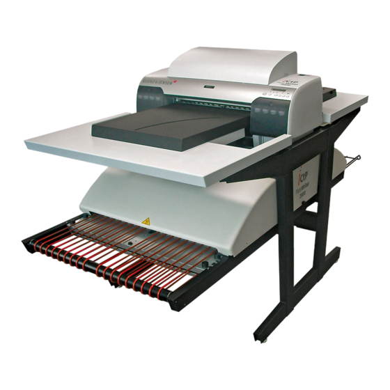
Page 12: Platewriter 2000 Overview
Introduction PlateWriter 2000 Overview PlateWriter 2000 Overview T11127 Front Plate Table: place plates here before printing. Control Panel: from here you control the Imaging Unit. Input table: Ensures that plates are aligned correctly prior to entering the Imaging Unit. Ink Dryer: improves the drying of the Liquid Dot ink on the plate. - Page 13 Introduction PlateWriter 2000 Overview T11128 13 Status Indicator LED: indicates the current status of the Finishing Unit. 14 Program Selector: for selection of the Curing Oven program. 15 USB-cable: connects the Imaging Unit with the RIP Workstation. 16 Power Cable: supply voltage for the Imaging Unit.
- Page 14 Introduction PlateWriter 2000 Overview Operating Manual 1036...
-
Page 15: Part 2: Daily Use
Overview Part 2: Daily Use Overview The daily use procedures described in this chapter cover the following issues: Daily Start-Up procedure • Loading of plates into the PlateWriter 2000 for printing • Printing of plates • Finishing • Daily Shut-Down procedure •... - Page 16 " This will also switch on the Ink Dryer. T11114 Switch on the PlateWriter 2000 by press- • ing the [POWER] button. The PlateWriter 2000 initializes and when • finished, the display shows ”READY”.
-
Page 17: Making A Proof
Daily Use Making a Proof Making a Proof Creating Files for Proofs Use your DTP application to prepare a composite output file - please refer to your • application manual for help. Select an output page size sufficiently large to accommodate your content and any registration marks or colour bars. -
Page 18: Making Plates
Save the file to a folder, either on the computer running Navigator RIP or on a • server. Loading Plates on the PlateWriter 2000 The input table ensures that plates are fed into the printer correctly. The side register rollers (see below) enable correct and easy alignment prior to entering the printer. -
Page 19: Imaging The Plate
Select Navigator -> Print file from the RIP menu. • Choose an appropriate PlateWriter 2000 Page Setup that matches your print job and the orientation of the loaded plate, then choose a file type (.ps, .pdf, .eps, .jpg or .tif). - Page 20 Uncheck Disable Output in the Output Controller/Monitor window. The first plate • will be printed. Remove the plate from the PlateWriter 2000 and place it on the front of the finishing • unit, see finishing procedure in the following section.
-
Page 21: Finishing
Daily Use Imaging the Plate Finishing Use +/- buttons on the Program Selector • (1) to select program: 1 = 0.15 mm plates 2 = 0.20 mm plates 3 = 0.30 mm plates 4 = Gumming only/Gum Rinse " Program 0 is for technicians only! Make sure that the indicator (2) lights •... -
Page 22: Daily Shut-Down
Daily Use Daily Shut-Down Daily Shut-Down Switch the unit into OFF-mode by press- • ing and holding the [POWER] key (1) for 2 secs. All lights turn off and the display will go blank. Never switch off the main power while the printer is running. -
Page 23: Part 3: Cleaning & Maintenance
Cleaning & Maintenance Overview Part 3: Cleaning & Maintenance Overview This section describes the various procedures for care and maintenance such as: Printer Cleaning the printer body • Cleaning the printer ink system • Additional printer settings and check • Finishing Unit Replacing the Gum/Finisher Solution (Daily) •... -
Page 24: Inks And Fluids
Cleaning & Maintenance Inks and Fluids Inks and Fluids The PlateWriter 2000 requires the use of various inks and fluids for processing, cleaning and maintenance purposes: IN G IN G • F • F LA M LA M • H •... -
Page 25: Replacing The Ink Cartridges
Cleaning & Maintenance Replacing the Ink Cartridges Replacing the Ink Cartridges If ink runs out, replace the cartridges as described in the following. Never use any ink other than genuine Liquid Dot ink from Glunz & Jensen. Doing so may result in malfunction or faulty operation. Care and Handling of Ink Cartridges Give attention to the following points when handling ink cartridges. -
Page 26: Other Printer Cleaning Tasks
Cleaning & Maintenance Other Printer Cleaning Tasks Other Printer Cleaning Tasks General Exposed areas of the machine may become soiled with ink during printing. The cleaning methods described below let you continue printing without affecting the printed media or the machine. When carrying out any cleaning other than cleaning using cleaning sticks, switch off the main power (before turning off the main power, press the [POWER] key to switch off the sub power.) -
Page 27: Finishing Unit
Cleaning & Maintenance Finishing Unit Finishing Unit Running the Gum Rinse Program It is recommended to run the Gum Rinse Program at the end of each working period (preferably once a week). Replace the solution in the Gum/Finisher bottle with warm water. •... - Page 28 Cleaning & Maintenance Finishing Unit T11122 Operating Manual 1036...
-
Page 29: Cleaning Of Gum/Finisher Rollers
Cleaning & Maintenance Finishing Unit Cleaning of Gum/Finisher Rollers " It is recommended to perform this cleaning procedure once a month. (See illustration opposite) Switch off and unplug the Finishing Unit. • Remove the Gum Dryer (1). • Remove the Gum Section Cover (2). •... -
Page 30: Gum/Water Replenishing System
Cleaning & Maintenance Finishing Unit Gum/water Replenishing System Depending on the size of the plate, the finishing unit sets aside a little water pump • run time (approximately 1 s for every 60 seconds that the finishing unit is running). Once the plate has passed through the machine, the water pump replenishes the re - served amount of water and distributes it to clean the rollers. -
Page 31: Part 4: Using The Rip
- which in this case is either the PlateWriter 2000 or a proofing device. In general, a software application or hardware device that performs this task is known as ®... -
Page 32: Basic Concepts And Definitions
Printing Glunz & Jensen Factory Defaults installs: PW2000_371/219 which is a Cali- bration Curve for PlateWriter 2000 with the device PW2000 2Ch Standard using Glunz & Jensen i-plates. Using the device PW2000 2Ch VSD no curve is added, as we recommend running without as calibration is build into the 3PWIV screening. - Page 33 Using the RIP Basic Concepts and Definitions ers. Within the Config dialogue box for each proofing device are several built-in cali- bration curves (shown with Green ticks) for various Epson papers and inks. Actual Press Curves: are used to linearize dot gain from the printing press, or to em- •...
-
Page 34: Setting Up Devices
Using the RIP Setting Up Devices Setting Up Devices Make sure that the PlateWriter 2000 is on and connected to your computer. • Start the Navigator RIP and select Navigator > Device Manager from the applica- • tion menu. Ensure the PW2000.i32 appears in the Window. If it does not, then check that you •... - Page 35 Using the RIP Creating Separation and Progressive Styles Predefined Separations Styles To make things easier, if you printed the Glunz & Jensen Factory Defaults file as described earlier, then it will have already installed some separations styles for you. Select Color -> Separations Manager from the Navigator RIP menu. •...
- Page 36 Using the RIP Creating Separation and Progressive Styles The New Style... window opens. • Give the new style a name that will be easy to remember and reflects what your • separation style will achieve (e.g. Composite CMYK to Deeds 3PWIV). Set Color space to CMYK.
- Page 37 Now set the screen to be applied to the image. Set the Dot shape to Deeds 3PWIV, • this is the Dynamically Even – Extended Diffused Screens that have been designed specifically for the PlateWriter 2000. Check the Generate extra gray levels box, and set Limit number of distinct gray •...
-
Page 38: Creating Page Setups For Plate-Making
Using the RIP Creating Page Setups for Plate-making Creating Page Setups for Plate-making About Page Setups The Navigator RIP allows multiple page setups, each can be used to describe how to handle a job that arrives at the RIP. The page setup identifies which device will be used to output the file, which separation style will be applied and thus the screening used to create the halftone. -
Page 39: Creating Page Setups
Using the RIP Creating Page Setups for Plate-making This opens the Page Setup Manager window. • Here two different page setups are created for each press, e.g. GTO52 CMYK 1440 and GTO52 CMYK 2880 either for the device 2Ch VSD or 2Ch Standard. Also you will find several other setups. - Page 40 Using the RIP 4-10 Creating Page Setups for Plate-making The Page Setup Manager dialogue appears. • Click on New… The New Page Setup window opens. • In the Output Device section select the device PlateWriter 2Ch VSD and check that •...
- Page 41 Using the RIP 4-11 Creating Page Setups for Plate-making The configuration window for the PlateWriter 2000 plug-in opens. • Make the settings as shown in the screen image. For a detailed description of the • PlateWriter 2000 plug-in, please see page 4-12 Click OK to continue.
-
Page 42: Platewriter 2000 Plug-In Functionality
Depending on the selected device, type the plug-in needed to find out which of the channels is charged with ink in the PlateWriter 2000. This will be indicated by the device name, either by 1Ch or 2Ch included in the device name. The plug-in will write Select One Print Head or Select Two Print Heads. -
Page 43: Options
2 channel device or vice versa without getting a RIP error: ! Error : Incorrect number of output channels (1) selected for PlateWriter 2000 2Ch Standard. ! ERROR : Image is 2BPP, should be 1BPP! Please re-RIP with a different screen. -
Page 44: Media
Using the RIP 4-14 PlateWriter 2000 plug-in functionality and a maintenance cycle job will be sent to the print spooler. Give more time to Windows The item Give More Time For Windows should normally be checked. If the RIP output speed seems slow and there is at least 512 MB RAM in the PC, the box can be unchecked and the results be compared. -
Page 45: Advanced Imaging Options
Using the RIP 4-15 PlateWriter 2000 plug-in functionality Plate Vacuum % The vacuum on the plate during transportation and printing can be set in a range from 0 – 150%. The default value is 30%, which should be sufficient to ensure enough vacuum, and at the same time allow a smooth transportation of the plate. - Page 46 RIP. Dot Size Two modes of dot sizes can be selected for the PlateWriter 2000 depending on the chosen resolution and number of channels: Printing in 1 channel VSD or 2 channel VSD (Variable Dot Size) mode on 1440x1440 •...
- Page 47 Using the RIP 4-17 PlateWriter 2000 plug-in functionality Better (slower) weaving, square resolutions Better (slower) weaving, square resolution should not be activated as default; this option is currently not implemented. Late screening This section is greyed out and default on the setting None and is not in use in this current version of the plug-in.
- Page 48 Using the RIP 4-18 PlateWriter 2000 plug-in functionality Screen Linearisation Control The Screen Linearisation Control is designed to work with variable screening such as the 3PWIV, the V in the end stands for variable. Here a Baseline, Step size and Curvature must be set to make the screening output more dynamic.
- Page 49 Using the RIP 4-19 PlateWriter 2000 plug-in functionality Set Tone Curves to None • – Set Intended Press to GJ PT1 and PT2, or another curve that matches your request. As CTP equipment is generally calibrated to provide a linear press sheet, this adds back the gain normally expected by conventional printing presses and thus creates a richer output for 4 colour work than a linear press sheet would.
-
Page 50: Setting The Plate Size
Using the RIP 4-20 PlateWriter 2000 plug-in functionality In the Cassette & Page section click the Page Layout.. button to open the Page Lay- • out window. Select units (inches or mm) for media size and margins. • Setting the Plate Size For printing plates set the Media Width and Media Length to the width and length •... -
Page 51: Setting The Gripper And Job Position On The Plate
Using the RIP 4-21 PlateWriter 2000 plug-in functionality Setting the Gripper and Job Position on the Plate Not all of the plate can be reproduced. Furthermore, to reduce press make ready time, it is desirable to place the job at the same starting point in terms of height, and in the centre of the width of the plate. - Page 52 RIP. " Please note that running the SM52 format on the PlateWriter 2000 requires the Paper Size Check is set to OFF, this is the maximum plate size that can be imaged on the PlateWriter 2000.
- Page 53 Using the RIP 4-23 PlateWriter 2000 plug-in functionality Click OK to return to the New Page Setup window. • Click the Save As... button. In the appearing Save Setup dialogue… • ...give your Page Setup a name which reflects the press size, and if necessary the Separations Style so it will be easy to select later.
- Page 54 Centre of Plate Width Media Width If your plate size allows it, in many cases it will be quicker for the PlateWriter 2000 to print the plate in Landscape orientation due to the fact that the plate has less far to advance.
- Page 55 Using the RIP 4-25 PlateWriter 2000 plug-in functionality Example of an Heidelberg QM46 press: • The plate size is 340 mm x 505 mm, and normally the narrow edge (340 mm edge) • would be the grip and so would normally be the top.
- Page 56 Using the RIP 4-26 PlateWriter 2000 plug-in functionality Click OK to return to the New Page Setup window. • In the Effects section set Rotate to the required rotation that matches depending on • the PostScript or pdf file and if you have a portrait or landscape press.
- Page 57 Using the RIP 4-27 PlateWriter 2000 plug-in functionality In the appearing Save Setup dialogue… • ...give your Page Setup a name which reflects the press size and if necessary the Separations Style so it will be easy to select later.
-
Page 58: Duplicating And Editing Existing Page Setups
Using the RIP 4-28 PlateWriter 2000 plug-in functionality Duplicating and Editing existing Page Setups Overview One of the easiest ways to create new page setups is to duplicate an existing one and change the items you require. The most common requirement is to create Page Setups that match different presses and plate sizes. - Page 59 Using the RIP 4-29 PlateWriter 2000 plug-in functionality " If you already have a Press Setup created, and you wish to add another of a different size, then try to select a Setup with the same orientation (e.g. if you have a Portrait Press setup such as an Heidelberg QM46 and want to create a different size such as a ABDICK 9810) and copy this Page Setup.
- Page 60 Using the RIP 4-30 PlateWriter 2000 plug-in functionality The New Page Setup window will appear. • Click on the Page layout... button. In the Page Layout dialogue… • ..edit the existing Media Width and Media Length settings to reflect the plate size of your new press page setup.
- Page 61 Using the RIP 4-31 PlateWriter 2000 plug-in functionality You will be returned to the New Page Setup window. • Click Save As... to save your new Page Setup with the new plate size. Give your new Page Setup a name to reflect the setting you have selected.
- Page 62 Using the RIP 4-32 PlateWriter 2000 plug-in functionality In the Page Setup Manager dialogue... • ...verify that your new Page Setup appears in the list. Click OK to exit. " If you click “Cancel” at any point including to exit the Page Setup Manager above, then any changes you made or new Page Setups will be lost! You have now completed creating your new Press Page Setup.
-
Page 63: Printing A Job Using The Rip
Using the RIP 4-33 Printing a Job Using the RIP Printing a Job Using the RIP Using the Print File Command When you select Print File from the Navigator RIP menu, the dialogue box shown below appears. Ensure you choose an appropriate Page Setup for printing the files, from the Page Setup drop-down list. -
Page 64: Printing Several Files
Using the RIP 4-34 Printing a Job Using the RIP Printing several files To print out several files at once, just select more than one file from the Print File dialogue box before clicking Print. The following keys make this possible: You can select a contiguous block of files by selecting the first file in the block, then selecting the last file in the block while holding down the Shift key. -
Page 65: Automating Job Input To The Rip
Using the RIP 4-35 Automating Job Input to the RIP Automating Job Input to the RIP Printing using Managed Input Plug-ins or 'Input Queues' This section describes the different ways in which the Navigator RIP can accept input, and how to configure the RIP to use each type of input. There are several ways of providing input to the Navigator RIP: Using the Print File menu command, as described previously. - Page 66 Using the RIP 4-36 Automating Job Input to the RIP AppleTalk • This publishes Page Setups in the RIP as a printer(s) on AppleTalk networks and lets the RIP accept input from any Mac application that prints to the printer(s) broadcast by the RIP.
-
Page 67: Managing Input Plugins
Using the RIP 4-37 Automating Job Input to the RIP Managing Input Plugins You control input plugins using the Input Controller. Before creating new inputs or changing existing ones, check that you have an appropriate page setup which can be associated with each input. -
Page 68: Turning On The Input System
Using the RIP 4-38 Automating Job Input to the RIP Turning on the input system To start receiving jobs from the configured and enabled inputs, choose the NavigatorRIP -> Input Controller menu option or clicking the tool bar button. The tool bar button is the most frequently used way to start or stop the queues, and simply uses icons representing Traffic Lights. -
Page 69: Copying An Input Plugin
Using the RIP 4-39 Automating Job Input to the RIP Type a name for the Input plugin device in the Name text box. • The name is used to identify the source within the RIP. It may also be used "... -
Page 70: Configuring An Input Plugin
Using the RIP 4-40 Automating Job Input to the RIP Configuring an input plugin Configuring an input means giving details about how the input is to be handled, and setting up any hardware or software associated with the source. To configure an existing input plugin, select it in the Input Controller and click Edit. -
Page 71: Using The Spoolfolder Input Folder
Using the RIP 4-41 Using the SpoolFolder Input folder Using the SpoolFolder Input folder The spool folder input is the most popular managed input for PC users. The Spool plug-in regularly scans a specified disk folder (directory), and processes any PostScript-language files (and other suitable files) that are placed there. -
Page 72: Creating And Configuring A Spool Folder Input Source
Using the RIP 4-42 Using the SpoolFolder Input folder Creating and Configuring a Spool Folder Input Source To create and configure a new spool folder source do the following: Open the Input Controller dialogue box either by choosing the NavigatorRIP -> In- •... - Page 73 Using the RIP 4-43 Using the SpoolFolder Input folder Select the Page Setup you wish to receive and process jobs that arrive in the spool • folder (here we have selected the GTO52 Pre-Separated Page Setup). Give your input queue a Name (try to use names that reflect the PageSetup you are •...
- Page 74 Using the RIP 4-44 Using the SpoolFolder Input folder The Spool Folder Configuration window contains the following control items: • Spool Folder The current spool folder is shown in the text field beside this button. This location is where the RIP detects the arrival of files and considers them as possible jobs, by looking at the type of file and any file names excluded in the Filenames pre-fix list.
- Page 75 Using the RIP 4-45 Using the SpoolFolder Input folder Error Folder If a file fails to print, the RIP moves it to the error folder specified unless the Delete on error box is selected. If a file prints successfully, the RIP moves it to the Complete Folder specified unless the Delete on completion box is selected.
- Page 76 Using the RIP 4-46 Using the SpoolFolder Input folder Delete on completion Select this box if you want the RIP to delete files that the spool folder succeeds in printing. Otherwise the RIP moves these files to the Complete folder. "...
-
Page 77: Using The Appletalk Input Plugin
Using the RIP 4-47 Using the AppleTalk Input Plugin Using the AppleTalk Input Plugin With the AppleTalk Plugin, the user defines a name and defines a Page Setup from the RIP to associate to that name (Queue). The name (Queue) is then published by the AppleTalk input source over the Apple network. - Page 78 Using the RIP 4-48 Using the AppleTalk Input Plugin After you have entered the name, select AppleTalk from the drop down menu in • the Type box. The AppleTalk Input Plugin is one of the simplest to set up, and there is nothing that needs to be configured for this plugin, so you can now click OK and the plugin is ready to use.
-
Page 79: Using The Nt Print Input
Using the RIP 4-49 Using the NT Print input Using the NT Print input This input publishes the RIP as one or more printers available to the Windows environment. Once fully installed and configured, each printer has a name visible to Windows operating systems. -
Page 80: Creating An Nt Print Input
Using the RIP 4-50 Using the NT Print input Click on Browse and select the folder where your RIP is installed. • This should be C:\Program Files\Xitron_72r1. Click OK Wait for the installation process to finish… • ...then reboot the computer. Creating an NT Print Input Having installed the plugin as described above, you can create a Navigator RIP input. - Page 81 Using the RIP 4-51 Using the NT Print input Choose NT Input from the Type drop-down list. • Select a Page Setup then check the Enabled box. • Click the Configure button. The NT Print Configuration dialogue box appears. • The dialogue box contains controls to allow for the situation where RIP inputs have started up before the Windows spooler system - this is possible on fast machines.
-
Page 82: Creating A Printer Under Windows Xp
Using the RIP 4-52 Using the NT Print input Creating a Printer under Windows XP You have two options. Either you can create a new printer to use the RIP channel, or you can connect an existing printer to the RIP channel. The procedures are similar for Windows XP and Windows 2000. - Page 83 Select one of these and click OK. Configure the printer. To do this you need to install the printer driver for the • PlateWriter 2000 supplied on the PlateWriter 2000 Installer CD or located in the di- rectory C:\GJ Tools\Windows PostScript Driver. Click Have Disk…...
- Page 84 Using the RIP 4-54 Using the NT Print input Insert the PlateWriter 2000 Installer CD ROM or go to C:\GJ Tools and open the • Windows Postscript Driver folder. Select the iCTP_Win2K-XP file and click Open. Click OK. • The iCTP Postscript Driver will be displayed.
- Page 85 Using the RIP 4-55 Using the NT Print input Now you must give your printer a name. By default Windows will use the iCTP • Postscript driver name, however you will want to choose a name, to reflect which Page Setup the jobs will be delivered to for users using this queue. Name the printer (we suggest you use the PageSetup name or something close to it).
- Page 86 Using the RIP 4-56 Using the NT Print input Windows will ask you if you want to print a test page. • This is not necessary, so select No and click Next. • Finally, you will see a Completion screen summarizing the details fo the printer you •...
-
Page 87: Using The Printer From Windows 2000/Xp
ExtremeZ-IP. This installer is automatically copied into your AppleTalk folder in the RIP folder, during installation or found on the PlateWriter 2000 installer disk. For details of the ExtremeZ-IP application please refer to the Manual supplied in this folder. -
Page 88: Calibrating
Using the RIP 4-58 Calibrating Calibrating Why Calibrate The function of Calibration Curves is to linearize output on your plates. There are several approaches on the use of the remaining curves. Generally, if you use the actual press calibration curve to linearize your press then you will be printing with linear plates that will produce flat images. - Page 89 Using the RIP 4-59 Calibrating If necessary, open the Output Controller / Monitor window by either pressing • Ctrl+O or choosing Output -> Output Controller from the RIP menu. Make sure that Disable Output is checked. This will allow you to control the start of •...
- Page 90 Using the RIP 4-60 Calibrating Click on the Info button to open the ThroughPut Info dialogue. • Click on Page layout..• Check that the Media Width, Media Length and Margins are correct for your plate. • (The calibration target is rather small, but you should check to ensure the margins will put it inside your printing area).
- Page 91 Once the Throughput window shows activity, re-check the Disable Output checkbox. A target similar to this illustration will be printed. After the target has printed, remove the plate from the PlateWriter 2000. • Place the plate on the front of the PlateWriter 2000's finishing unit.
- Page 92 Using the RIP 4-62 Calibrating Choose Output -> Calibration Manager from the RIP menu. • Choose Printing Press as the Device type. • Select CMYK as the Colour Space. • Click on New..• Name the new calibration in relation to the press and paper type that was used. •...
-
Page 93: Including The Press Calibration In Page Setups
Using the RIP 4-63 Calibrating Including the Press Calibration in Page Setups Editing the Page Setups Choose Page Setup Manager from the RIP menu to open the Page Setup Manager • window. Select the Page Setup that was used when printing the uncalibrated target and click •... -
Page 94: Why Use Intended Press Or Tone Curves
Why Use Intended Press or Tone Curves? The calibration process we have outlined is used to linearize the printing process using the PlateWriter 2000. Linear printing means that a nominal 50% dot (gray level) will print as 50% on press. -
Page 95: Backup & Restore Your Navigatorrip Configuration For Windows
Using the RIP 4-65 Backup & Restore your NavigatorRIP Configuration for Windows Backup & Restore your NavigatorRIP Configuration for Windows " It is very simple to backup your configuration of the Navigator RIP. If you follow this simple backup procedure, you will preserve all of your Passwords, Memory settings, Calibrations, Tone Curves, Device and Page Setups etc. - Page 96 Using the RIP 4-66 Backup & Restore your NavigatorRIP Configuration for Windows Operating Manual 1036...
-
Page 97: Part 5: Troubleshooting
Troubleshooting General Part 5: Troubleshooting General If the PlateWriter does not work properly, refer to the following pages to find the paragraph that comes closest to your problem. " To change a fuse, switch off all power to the machine first. Always ensure that the new fuse is of the correct size and rating according to the diagram. -
Page 98: Problems With The Finishing Unit
Troubleshooting Problems with the Finishing Unit Problems with the Finishing Unit Indicator status and Error Codes The finishing unit's status indicator lamp has several ways to indicate the current status of the unit and/or unit errors. GREEN - STEADY Finishing unit is ready. Program selector may be changed before plate is placed on conveyor. -
Page 99: Bi-Directional Adjustment On Platewriter 2000
Appendix A: Bi-directional adjustment on PlateWriter 2000 Appendix A: Bi-directional adjustment on PlateWriter 2000 Start the Program “PWAdjUtil” from the folder C:\GJ tools\PWAjUtil on the RIP workstation. Select the printer connected. Select printer type and set Adjustment job to Bidirectional and click on Narrow (*). -
Page 100: Adjusting The Printer Feed
Appendix A: Adjusting the printer feed Adjusting the printer feed Background In continuance to increase the print quality we often get questions on graininess. The number one adjustment that reduces grainy looking tints is the printer feed adjustment. The printer already has a feed adjustment built in but since the correction depends on the plate thickness the correction value must be set in the page setup. - Page 101 Appendix A: Adjusting the printer feed Measure the longest possible line 250, 450 or 600 mm and find the deviation factor as shown. In this case the feeds needs to be adjusted +0,16% measured at the 25 cm point. Open the page set-up(s) with plate gauge identical to the one performed for the above test and key in the new value in the Feed adjustment in the “Configure Device.”...
Need help?
Do you have a question about the PlateWriter 2000 and is the answer not in the manual?
Questions and answers