ATH Heatnet KN-6 Control Manual
Kn series cast iron condensing boilers
Hide thumbs
Also See for Heatnet KN-6:
- Installation and operation instructions manual (44 pages) ,
- Operation instructions manual (144 pages) ,
- Manual (52 pages)
Table of Contents
Advertisement
instructional information provided with the boiler. Install, start and service the boiler only in the sequence and methods given in these
instructional information provided with the boiler. Install, start and service the boiler only in the sequence and methods given in these
instructions. Failure to do so can result in severe personal injury, death or substantial property damage.
instructions. Failure to do so can result in severe personal injury, death or substantial property damage.
Do not use the boiler during construction.
Do not use the boiler during construction.
the burner, resulting in possible severe personal injur
the burner, resulting in possible severe personal injur
free air supply. Follow the instruction manual procedures to duct air to the boiler air intake. If the boiler has been contaminated by operation
free air supply. Follow the instruction manual procedures to duct air to the boiler air intake. If the boiler has been contaminated by operation
with contaminated air, follow the instruction manual guidelines to clean, repair or replace the boiler if necessary.
with contaminated air, follow the instruction manual guidelines to clean, repair or replace the boiler if necessary.
x these instructions near to the boiler/water heater. Instruct the building owner to retain the instructions for future use b
x these instructions near to the boiler/water heater. Instruct the building owner to retain the instructions for future use b
service technician, and to follow all guidelines in the User's Information Manual.
service technician, and to follow all guidelines in the User's Information Manual.
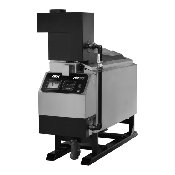
Cast Iron Condensing Boilers
Models K N-6, KN-10, KN-16,
KN-20, KN-26 and KN- 30
Control adjustment and operation instructions
for Advanced Thermal Hydronics firmware
version 2.04.
This instruction manual applies only to Advanced
Thermal Hydronics firmware version 2.x on version
3.x control boards. Current firmware is backwards
compatible with version 1.x & 2.x boards, but some
current features may not be available. To replace
firmware on an existing boiler, contact the factory
to obtain the original firmware file or for assistance
in applying current firmware to an older version
control board.
Also read and follow:
er/technician. Read and follow this manual, all supplements and related
er/technician. Read and follow this manual, all supplements and related
Construction dust and particulate, particularly drywall dust, will cause contamination of
Construction dust and particulate, particularly drywall dust, will cause contamination of
With Touch Screen Display
KN-Series Gas Boiler Installation
and Operating Instructions
e boiler can only be operated with a dust-
e boiler can only be operated with a dust-
KNV3
Advertisement
Table of Contents

Related Manuals for ATH Heatnet KN-6


Summary of Contents for ATH Heatnet KN-6
- Page 1 KNV3 With Touch Screen Display Cast Iron Condensing Boilers Models K N-6, KN-10, KN-16, KN-20, KN-26 and KN- 30 Control adjustment and operation instructions for Advanced Thermal Hydronics firmware version 2.04. This instruction manual applies only to Advanced Thermal Hydronics firmware version 2.x on version 3.x control boards.
- Page 2 INFORMATION HeatNet Control V3 2.x Information contained in this publication regarding device applications and the like is provided only for your convenience and may be superseded by updates. It is your responsibility to ensure that your application meets with your specifications. Advanced Thermal Hydronics MAKES NO REPRESENTATIONS OR WARRANTIES OF ANY KIND WHETHER EXPRESS OR IMPLIED, WRITTEN OR ORAL, STATUTORY OR OTHERWISE, RELATED TO THE INFORMATION, INCLUDING BUT NOT LIMITED TO ITS CONDITION, QUALITY, PERFORMANCE, MERCHANTABILITY OR...
-
Page 3: Table Of Contents
TABLE OF CONTENTS HeatNet Control V3 2.x TABLE OF CONTENTS TABLE OF CONTENTS ..........................3 Introduction ..............................5 KN-S V3 H ............................. 5 ERIES ONTROL Features & Specifications ......................... 7 ................................ 7 TANDARD EATURES VERVIEW Specifications ............................9 Components & Accessories ........................10 ................................. - Page 4 TABLE OF CONTENTS HeatNet Control V3 2.x Stack Temperature ..........................33 Security ..............................34 Saving Configuration Settings ....................... 34 USB Features ............................34 Diagnostics .............................. 34 Blower Protection ............................ 35 Communications ............................. 35 Failsafe Modes ............................35 FAILSAFE REQUIREMENTS: ............................... 35 Flow Options ............................
-
Page 5: Introduction
FEATURES & SPECIFICATIONS HeatNet Control V3 2.x The primary purpose of the control is to maintain the boiler Introduction water temperature at the supply or the header sensor using a target setpoint. This function is displayed in the Home Screen. While performing this task, the control also monitors dedicated external limits in a limit string and The KN-Series V3 HeatNet Control provides an orderly shutdown and fault indication in the... - Page 6 FEATURES & SPECIFICATIONS HeatNet Control V3 2.x boilers are staged on and modulated up until the Heat Band ADAPTIVE MOD:DROP DOWN. Once the Main Valve is entered. Once in the Heat Band, modulation is used to (on the newly added boiler) is opened, and the DELAY maintain setpoint.
-
Page 7: Features & Specifications
FEATURES & SPECIFICATIONS HeatNet Control V3 2.x firmware program that always remains resident so that a Features & Specifications factory program can be restored. Primary loading is with a flashdrive. HeatNet Version 3.x Discontinued Support for High Efficiency Ametek blowers. Features from Version 2.x Control 10. - Page 8 FEATURES & SPECIFICATIONS HeatNet Control V3 2.x 10. Menu driven calibration and setup menus with a bright 23. Remote 4-20mA setpoint control using a mapped (Adj.) 4 line Vacuum Fluorescent Display. setpoint range to the 4-20mA control signal. 11. (8) Dedicated 24vac interlock monitors, and 8 dedicated 24.
-
Page 9: Specifications
FEATURES & SPECIFICATIONS HeatNet Control V3 2.x Specifications Control Microprocessor based PID modulating control ( NOT a safety limit ) Environment -40 °F to 140 °F, <90% RH non-condensing Input Power 24 VAC, 500 ma Relays System Pump, Damper, Circulator, Alarm, DHW Pump (v2.x), 8A 250 VAC resistive K8 on J4.2 &.6 for Base Loading version 2.x Control 24 VAC –... -
Page 10: Components & Accessories
Components & Accessories Part Number Component 40-00751-001 KN-Series Control Board Version 3.x 40-00752-001 Graphics Display Board 40-00752-002 Color Touch Panel Display 02-3926 ACI/10K-CP-BP Temperature probe (bullet type, 1x.250 inch) 02-4283 ACI 10k-CP-I-NW Supply, Header, Return Sensors 02-4285 ACI CP-I-2.5” Sensor with well 02-4286 ACI CP-I-4”... -
Page 11: Setup & Operation
SETUP & OPERATION HeatNet Control V3 2.x The Master now checks all of the runtimes to determine SETUP & OPERATION which boiler has the least runtime based on the MIN RUNTIME setting in SETTINGS:FIRING MODE:. The MIN RUNTIME setting is the minimum runtime interval in hours that is used to compare boiler to boiler runtimes. -
Page 12: Mixed Boiler Types Using Priority Sets
SETUP & OPERATION HeatNet Control V3 2.x used, a soft start speed is applied before the pre-purge When the header water temperature first exceeds the top of speed. the heating band, the boilers are again checked for the one with the most runtime. The selected boiler will turn off After air-flow is established the ignition control waits immediately and a shed boiler delay timer will be loaded for the air switch to close. - Page 13 SETUP & OPERATION HeatNet Control V3 2.x will fire first/next based on runtime. This has the effect of flipping the Priority of the sets. Stopping Boilers: When a boiler is to be stopped (water temp is above the heating band), the Master checks the HeatNet boilers it has available.
-
Page 14: Start/Stop Priority Conditions
SETUP & OPERATION HeatNet Control V3 2.x In the example Mixed Boilers: Condensing/Non- The Return water temperature is below 140F and condensing occurs. (The Master‟s system return water Condensing, condensing boilers and non-condensing boilers are used, but other combinations may also be used. Another would need to be used.) example could use (2) small boilers and set them to The Outside Air Temperature is above a setpoint... -
Page 15: Selecting Mixed Boilers
SETUP & OPERATION HeatNet Control V3 2.x Selections (always the highest runtime first): combination of the Start and Stop conditions may be applied for best performance and economy in the system. Also, non- The condensing boiler set (Priority 1) has a condensing boilers may be set to go offline when a return higher Priority to stop when one of these temperature is too low using the SETTINGS: HEAT... - Page 16 SETUP & OPERATION HeatNet Control V3 2.x When boiler types are the same, the system turndown is KN6, KN6, 55:1 KN2, KN2 limited to the boiler‟s min input and fault tolerance is always present. When the system has mixed boiler types, KN2, KN2, KN10, KN10, 90:1...
- Page 17 SETUP & OPERATION HeatNet Control V3 2.x Example: (2) KN6s, (2) KN20s In the Mixed Boiler System table (line 1), KN6s are set as Priority 1 and KN10‟s set as Priority 2. With a MOD MAX Redundancy: (120 + 400)/600 = 87% No Redundancy: (120 * 2) + 400)/(600*2) =54% of 60%, each KN6 can run to 360M (720M total) before a KN10 is called ON (Add Delay timer set long enough).
-
Page 18: Mixed System Type 2: Condensing / Non-Condensing
SETUP & OPERATION HeatNet Control V3 2.x Figure 8 Boiler System Response 2 Figure 10 Boiler System Response 4 (1) KN6, (1) KN20, 60% Mod-Max (2) KN2s, (3) KN6s To correct this would require the KN6 to set the MOD- The above Boiler System Response 4 graph illustrates MAX to roughly 90% (Boiler System Response 3: not as another system where 80% is used as the MOD-MAX... - Page 19 SETUP & OPERATION HeatNet Control V3 2.x Figure 12 Mixed Boilers: Example: Condensing/Non-Condensing FIRING MODE (MASTER) BOILER TYPE & (All Boilers in Set) BOILER TYPE All Boilers in Set PRIORITY 2 PRIORITY 1 Non-Condensing (Set) Condensing (Set) Master Figure 13 FIII Boiler Btu Chart (MBH) KN Boiler Btu Chart (MBH) MB/MW...
- Page 20 SETUP & OPERATION HeatNet Control V3 2.x Normally, the Priority 1 boilers will fire first. Once all the requires that the Priority 1 boiler be set up to start first Priority 1 boilers are firing, the next boiler to fire (after the and stop last.
-
Page 21: Base Loading, Relay Control
CONTROL METHODS HeatNet Control V3 2.x Base Loading, Relay Control The control has the ability to control (1) base load boiler using the K8 Relay contacts on J4 pins 2 & 6. In order to connect to this plug, (2) wires with pins are required and inserted in J4. - Page 22 CONTROL METHODS HeatNet Control V3 2.x million BTUs and the HeatNet boilers modulate down to down to low fire. At this point, the (3) smaller boilers need 25% for a total output of 2 million BTUs and running at to shut off or the Base load boiler would need to shut off. high efficiency.
-
Page 23: Setting Up Base Loading
CONTROL METHODS HeatNet Control V3 2.x Return Water Temperature Setting up base loading START menu item: The relay contact will The base load boiler is controlled using a set of contacts to close to enable the boiler when the RETURN enable it (location J4). -
Page 24: Heating Control Methods
CONTROL METHODS HeatNet Control V3 2.x Short cycling may occur when a firing rate is sent to a member boiler that would cause the Heating Control Methods supply temperature to raise high enough to trip the operating limit (low flow rate). After An overview of the (5) methods for controlling the KN the supply temperature falls, the boiler would series boiler are presented here. -
Page 25: Heating Method 1 Heat Demand
CONTROL METHODS HeatNet Control V3 2.x external control is not present, has failed, or needs to be Master boiler enabled or disabled. A member can override the H-Net The MASTER boiler controls the system using a PID commands using this input. algorithm. -
Page 26: Heating Method 2 Stage Control T1-T2
CONTROL METHODS HeatNet Control V3 2.x A 20ma signal will fire the boiler at the maximum firing Heating Method 2 rate. The input current signal is viewed as a percentage to STAGE Control T1-T2 the boiler from 0 to 100% (0-20mA). This means that a 20% (4mA) input signal is required to start the boiler, but The boiler can also be operated in 2 separate stages using since the boiler is classified as having example:4:1 turn... - Page 27 CONTROL METHODS HeatNet Control V3 2.x Protocessor option Figure 19 MODBUS connections An optional BACnet or LonWorks bridge module can be used to connect the MODBUS network to a BACnet or LonWorks network. Modbus Using Figure 20 Protocessor bridge module option RJ45 Cat 5 cable Building Management...
-
Page 28: Using The 4-20Ma Input (Optional)
OPTIONAL FEATURES HeatNet Control V3 2.x Figure 22 4–20ma enable connection Using the 4-20ma input (OPTIONAL) The 4-20ma input is designed to operate per the ISA-50.1 standard. It will support Type 2, Type 3, and Type 4 Transmitter/Receiver circuits. The Type 2 and Type 3 circuit may use the supplied +24VDC and 24VDC RET connections (J10B) to power a remote transmitter. -
Page 29: Setpoint Priorities
OPTIONAL FEATURES HeatNet Control V3 2.x For non Ametek blowers, the minimum setting current is the lower setpoint. So, if we set the 4ma of the boiler is calibrated so that the minimum SETPOINT to 130F and the 20ma SETPOINT at 180F we PWM signal to control the Blower motor is will have established the band. -
Page 30: Circulator Pump Options
OPTIONAL FEATURES HeatNet Control V3 2.x 12:01 AM. If (2) system pumps are present, and after the first Circulator Pump Options pump finishes its post purge, the second one will start and the first one will stop. There are provisions for a system pump(s) and a local pump. The system flow proving switch is implemented using This is to allow for primary/secondary loop configurations. -
Page 31: Local Pump Options
OPTIONAL FEATURES HeatNet Control V3 2.x For system pump modulation a 0-10Vdc control signal The local circulator pump is supported by (3) modes and (2) output is provided at J4.3 (signal) and J4.7 (ground). This features. signal is output by the Master boiler as a percent function of the number of boilers running and can be used to set the speed The first mode allows the circulator pump to remain on, unless the control‟s outside high air temperature setting... -
Page 32: Combustion Air Damper
OPTIONAL FEATURES HeatNet Control V3 2.x A separate/independent 24 VAC source is Figure 24 Local & DHW Pump connections recommended to be used for the damper prove switch when a common system damper is used. If you use terminal 8 to supply power from the Master and the Master is powered OFF, no boiler will be allowed to fire due to the loss of power through the prove switch. -
Page 33: Outdoor Reset
OPTIONAL FEATURES HeatNet Control V3 2.x The chart depicts what the water temperature setpoint will Outdoor Reset equal with a corresponding outside air temperature. At an outside temperature of 10F and below, the water temperature setpoint will be limited to 180F. With an outdoor temperature The Outdoor reset feature allows the water setpoint of 70F and above, the water temperature will be limited to temperature to change dynamically with the outside air... -
Page 34: Security
OPTIONAL FEATURES HeatNet Control V3 2.x ALARM TYPE: is set to” FAULT” the boiler will halt and USB flash drive needs to have a directory called “firmware” the Alarm relay will close when the Stack temperature located in the root directory. The downloaded firmware .hex exceeds 350F. -
Page 35: Blower Protection
OPTIONAL FEATURES HeatNet Control V3 2.x If a pump fails (flow switch required), or the flow switch 2. In the event a blower lockout has been determined, a fails, the boiler will cycle the start condition every 10 minutes (10) minute retry cycle, (3) times will occur. At the time in an attempt get the boiler restarted. -
Page 36: Flow Options
OPTIONAL FEATURES HeatNet Control V3 2.x SETUP:AUX FUNCTIONS:FAILSAFE MODES. Low Temperature Protection LOW TEMP: OFF, SUPPLY, HEADER, DHW, or The following are types of Failsafe conditions. RETURN Building Management System Failure This mode may be used by the MASTER or MEMBER boiler and can be used as a type of freeze protection. - Page 37 OPTIONAL FEATURES HeatNet Control V3 2.x d. Set SETTINGS: FLOW METER: INPUT TYPE to The BTU load value may also be accessed through Modbus BMS. read registers 30242 (upper 16 bit word) & 30243 (lower 16 e. Set SETTINGS: FLOW METER: LOWEST FLOW bit word).
-
Page 38: Heatnet Online
OPTIONAL FEATURES HeatNet Control V3 2.x To activate this flow limited feature for use with an Onicon technicians on the road. If the technician has a smart phone, Flow Meter F-1210: they can be notified through the emails on their phone. They can then log on to the HeatNet Online website (from their phone) to determine the trouble. - Page 39 OPTIONAL FEATURES HeatNet Control V3 2.x Data Points can also be viewed in a manner other than a histogram as pictured below. The date/time picker can be used to mine the raw data stored on the HeatNet Online server. Runtime graphs of each boiler ensure even runtimes are being observed by a properly operating system.
-
Page 40: Domestic Hot Water Methods
OPTIONAL FEATURES HeatNet Control V3 2.x AUTO: will handle normal heating only applications. It Domestic Hot Water Methods may also be used when individual boilers have tanks connected and are controlled with the DHW BOILER? Domestic Hot Water control is supported using (6) methods. set to LOCAL. -
Page 41: Dhw Method 1: Dhw Heating Only Using A Dhw Master And Member Boiler(S) Employing H-Net
OPTIONAL FEATURES HeatNet Control V3 2.x DHW METHOD 1: DHW Heating ONLY using a A DHW call for heat is when the DHW temperature is below the (DHW SETPOINT – LOWER BAND) DHW MASTER and Member boiler(s) employing or when the DHW temperature is below the (DHW H-Net. -
Page 42: Dhw Method 2: Combination Dhw And Space Heating Using A Master Boiler And Member Boiler(S)
OPTIONAL FEATURES HeatNet Control V3 2.x B. Pump on the Master boiler functions as a global DHW METHOD 2: Combination DHW pump. and Space Heating using a MASTER Now, is the system to use a DHW sensor? USE Boiler and Member boiler(s) SENSOR in this example should be set to YES. - Page 43 OPTIONAL FEATURES HeatNet Control V3 2.x When using this method, a DHW band is also available in Set up the Master boiler first: the Home screen. The space heating band will be displayed Connect a 10k thermistor from the DHW tank‟s sensor on the left and the DHW Heating band on the right.
- Page 44 OPTIONAL FEATURES HeatNet Control V3 2.x This time includes the DHW post purge of the DHW purge to the TANK, or to the SPACE for the duration pump/valve. of the post purge time. This selection can use the space to dump the heat from the boiler and not overheat the Go to the POST PURGE menu item.
-
Page 45: Dhw Method 3: Dhw Heating Using A Header Sensor Input
OPTIONAL FEATURES HeatNet Control V3 2.x Now, there is one more thing to consider, the DHW METHOD 3: DHW Heating using pump‟s post purge time. Dumping the heat from a Header Sensor Input all boilers (that were running) using a pump post purge cycle will have an effect on the tank‟s This method will control a tank temperature when the tank water temperature. -
Page 46: Dhw Method 5: Dhw Of A Local Boiler S Tank
OPTIONAL FEATURES HeatNet Control V3 2.x mode is active. Setting this value to NO leaves the Main Heating Loop system pump on. This active period includes the post purge of the DHW pump/valve. LOCAL LOCAL 19. Select the menu item POST PURGE. This is the time that the DHW pump relay remains energized after the DHW thermostat has been satisfied. - Page 47 OPTIONAL FEATURES HeatNet Control V3 2.x 24. Next, enter the DOMESTIC HOT WATER menu on and wait to be called again for either space the Master boiler. Go to BOILER MODE and enter heating or DHW heating. A shutdown always LOCAL.
-
Page 48: Dhw Method 6: Dhw Using Direct Control
OPTIONAL FEATURES HeatNet Control V3 2.x Main Heating Loop DHW sensor will allow the placement anywhere needed to maintain that locations temperature. This is an LOCAL additional sensor that needs to be acquired. LOCAL A thermostat can be placed in a tank and connected to the Thermistor Sensor Thermostat OR OVR input. -
Page 49: Wiring Connections
OPTIONAL FEATURES HeatNet Control V3 2.x Wiring Connections Figure 27 Dip Switches and Wiring Wire Strip Length. .42” or If the terminal blocks are of the screwless type, the wire should be stripped to 10.67mm. to .25” or 6.34mm. If the terminal blocks are of the screw type, the wire should be stripped 4-20mA Input JS1: select, See:... - Page 50 WIRING CONNECTIONS HeatNet Control V3 2.x Figure 28 Heating Method 1 H-Net, Master/member RJ45 HeatNet In and Out The (2) LEDs on the RJ45 indicate: GREEN: Transmit Data YELLOW: Received Data HeatNet Boiler to Boiler Communications 3 wire Shielded HeatNet In and Out HeatNet Termination.
- Page 51 WIRING CONNECTIONS HeatNet Control V3 2.x Figure 29 Heating Methods 2 and 4: AA-High Fire and High/Low, master or member boiler Heating Mode 4: High Fire Close this contact to run boiler at Highfire. Heating Mode 2: Stage Control Inputs. T1 or T2 Closed: Lowfire T1 &...
- Page 52 WIRING CONNECTIONS HeatNet Control V3 2.x Figure 30 Heating Method 3 4–20 ma/ 0-10 VDC 24 VDC Return Channel 2: Channel 1: 4-20mA/0-10VDC 4-20mA/0-10VDC 24 VDC S6 along with the SETUP:ADVANCED:4-20mA INPUT menu configures the channel for operation. S6 switch 1 DOWN: 4-20mA channel 1 S6 switch 1 UP: 0-10VDC channel 1 S6 switch 2 DOWN: 4-20mA channel 2...
- Page 53 WIRING CONNECTIONS HeatNet Control V3 2.x Heating Method 5: MODBUS (Optional BACnet or LonWorks bridge — Protocessor) Figure 31 The (2) LEDs on the RJ45 indicate: GREEN: Transmit Data YELLOW: Received Data RJ45 Cat 5 Modbus 3 wire Shielded Modbus Modbus Termination.
- Page 54 WIRING CONNECTIONS HeatNet Control V3 2.x Figure 32 Relays, Interlocks and Boiler Status The Highest priority SYSTEM FLOW PROVE --------- Low Water Cutoff------------------- Variable Frequency Drive -------- Gas Pressure (High & Low) ----- Spare for user or Factory ------ Operator------------------------------ Water Flow Switch----------------- Factory ------------------------------ Low Voltage...
- Page 55 WIRING CONNECTIONS HeatNet Control V3 2.x Figure 33 Temperature sensors (REQUIRED) Water Temperature INLET (return) of Boiler All Temperature Sensors are 10k Thermistors. (OPTIONAL) Water Temperature Immersion sensors require a well. Common System Supply (Header) IF CONNECTED, BOILER = MASTER (OPTIONAL) DHW Temperature Domestic (REQUIRED)
- Page 56 WIRING CONNECTIONS HeatNet Control V3 2.x Figure 34 Typical Single Boiler System HEADER SENSOR (Determines Master Boiler) #4 SYSTEM PUMP LOCAL PUMP OUTDOOR ENABLE #14 ENABLE #8 DHW TANK SENSOR FLOW PROVE #9 FLOW PROVE AQUASTAT #13 North Away From Exhaust DHW TANK RETURN SUPPLY...
- Page 57 WIRING CONNECTIONS HeatNet Control V3 2.x Figure 35 Using a 4–20ma signal for direct modulation A control signal greater 20mA than 4.2mA (adjustable) will start boiler. Output Range From No Effect Control Control Signal Once boiler starts the control signal must Display input % of control when running drop below 4.01 mA to stop Boiler...
- Page 58 WIRING CONNECTIONS HeatNet Control V3 2.x Figure 36 Common system damper wiring MEMBER BOILER 2 MEMBER BOILER 1 Connection if Member boiler is running as Failsafe MASTER BOILER NOTE: Ensure that the Combustion Air Damper is enabled on all Boilers for use. SETUP MENU:AUX FUNCTIONS DAMPER Prove Switch...
- Page 59 WIRING CONNECTIONS HeatNet Control V3 2.x Figure 37 Failsafe common system pump wiring MEMBER BOILER 1 120 VAC Return DPST Relay Add additional relays/ contacts for more boilers System Flow Prove Switch 120VAC 120VAC 120 Return MASTER BOILER System Pump Voltage Return System Pump Voltage Feed System Pump...
-
Page 60: Home Screen Navigation
HeatNet Control V3 1.x Home Screen Navigation Temperatures Home Screen Master Boiler Status for Firing Boilers Temperature Charting Interlock, Ignition, and Binary Inputs Analog, Motor Tach, and Misc. Outdoor Reset if Active Boiler Runtimes Home Screen This diagram depicts the Home screen and subsequent screens when the right arrow button is pressed. Repeatedly pressing the right arrow button forms a ring of the different screens. -
Page 61: Home Screen
HeatNet Control V3 1.x Home Screen The Home screen is used to show the main temperatures in graphs along with some ancillary functions The Home Button in the upper left corner when pressed, will always enter the Home screen. Header Temperature DHW Temperature Pointer Pointer... -
Page 62: Home Screen Messages
HeatNet Control V3 1.x Home Screen Messages Status Line 1: Setpoint Source – Heating Mode Status Line 2: Running Status Status Line 3: Any Fault Information Heating Mode Messages: Control Signal An analog control signal on 4-20mA (1) input is controlling fire rate. DHW Tank A DHW thermostat or sensor is being used to fireboiler in a DHW mode Failsafe... -
Page 63: Setpoint Source Messages
HeatNet Control V3 1.x Setpoint Source Messages 0-10V Setpoint Settings are configured to allow a 0-10VDC signal to change setpoint. 4-20mA Setpoint Settings are configured to allow a 4-20mA signal to change setpoint. DHW Setpoint The DHW sensor is controlling the setpoint for DHW heating. Local Setpoint Boiler is watching the Local Setpoint. - Page 64 HeatNet Control V3 1.x Failsafe: Low DHW The boiler has entered Failsafe mode due to a low DHW temperature. Temperature Failsafe: Low The boiler has entered Failsafe mode due to a low Header temperature. Header Temperature Failsafe: Low The boiler has entered Failsafe mode due to a low Return temperature. Return Temperature Failsafe: Low...
- Page 65 HeatNet Control V3 1.x Input is Reduced If a stack sensor is used and temp exceeds limits. due to Stack Temperature IRI Alarm This is a 120VAC interlock used by the Gas Valve proving option. J5 Input VALVE ALARM. Minimum off Time The Minimum Off Time has been set on the boiler.
- Page 66 HeatNet Control V3 1.x Running The boiler is running and heating water. The Main Valve is open or this is the called for % of input. Running 100% The boiler is calling to run at 100% modulation. Shorted *** The *** indicates the temperature sensor which has shorted. *** Sensors are: Outside, Supply, Sensor Return, Header, DHW, Stack, and System Return.
- Page 67 HeatNet Control V3 1.x Waiting for This is the Damper proving time when the damper relay closes until the Damper prove interlock closes on J12B.7 & J12B.8. Damper to open Waiting for Flow This is the flow proving period that is in effect when starting the boiler. The pumps/valves would have been called on prior to this message.
- Page 68 HeatNet Control V3 1.x Master Boiler Status Screen The above screen on the Master boiler displays the start and stop timers that are used to bring on boilers below and shed them above the heating band. When the Header temperature is below the band, the Heat Start Timer (Add Boiler Delay Timer) is started.
- Page 69 HeatNet Control V3 1.x Pressing any of the Member buttons will bring up a Member‟s informational screen. Limited information is available for a Member from the Master boiler, including making Settings changes and the Log. These need to be viewed on each Member boiler directly. In the Bottom Left corner there is the Settings button which will allow changes to the operational settings of the boiler.
-
Page 70: Calibration
HeatNet Control V3 1.x below this. Once you are done with this setting, press the Calibration „X‟ key to throw out the setting or the check key to save. The calibration of the KN-Series boiler should only be performed by a licensed technician. -
Page 71: Log Entry
LOG ENTRY HeatNet Control V3 1.x Log Entry The top line, left corner indicates any condition that caused the event. This may be a fault (such as to indicate a sensor that has failed.) or general event as denoted by “Event”. The top line, right corner displays the time and date the event occurred. -
Page 72: Settings
DEFAULT SETTINGS & MENU ITEM DESCRIPTIONS HeatNet Control V3 2.x SETTINGS To Enter the Settings menus the first boiler button must be selected. The button is highlighted by the red box. Next, press the Settings box as also illustrated by the red box. The Settings Menu Page 1 will then be displayed. -
Page 73: Settings
DEFAULT SETTINGS & MENU ITEM DESCRIPTIONS HeatNet Control V3 2.x SETTINGS — PAGE 1 DEFAULT MENU RANGE DESCRIPTION VALUE # OF BOILERS (1-16) If operating as a member. # of first boiler to run, determines the fire order in rotation. A 0 LEAD BOILER # (0-16) disables the Lead Boiler function. - Page 74 DEFAULT SETTINGS & MENU ITEM DESCRIPTIONS HeatNet Control V3 2.x 4-20mA 4-20mA input is mapped to a setpoint. If set to YES, the boiler /system shuts down when the temperature WARM WEATHER SD ON-OFF exceeds the WWS SETPOINT. Temperature at which boiler shuts down, operation is below this. If boiler is running using either OA RESET or WWS and the OR (40 –...
- Page 75 DEFAULT SETTINGS & MENU ITEM DESCRIPTIONS HeatNet Control V3 2.x ON = Pump never shuts off. Used when there is only 1 system pump ALWAYS ENABLED ON/OFF in the system. Priority mode for the system pump while in Warm Weather Shutdown.
- Page 76 DEFAULT SETTINGS & MENU ITEM DESCRIPTIONS HeatNet Control V3 2.x DAMPER The LINKED/COMMON setting allows one common damper to be used and controlled by the Master Boiler. All Member boilers must LINKED/COMMON have their damper prove inputs wired as per Figure 36, Common TYPE INDEPENDENT system damper wiring, page 58.
- Page 77 DEFAULT SETTINGS & MENU ITEM DESCRIPTIONS HeatNet Control V3 2.x Not Available when operating in DELTA HIGH/LOW protection. Limit to Half Rate: When set to YES, and the maximum differential temperature (delta T) has been exceeded, the fire rate called for is cut in half.
- Page 78 DEFAULT SETTINGS & MENU ITEM DESCRIPTIONS HeatNet Control V3 2.x MIXED (Combination) allows the boiler to be configured to run as a space heating boiler and a DHW boiler that is controlled by a Master. This would use both the space heating PID and the DHW PID to simultaneously control space heating and DHW heating.
- Page 79 DEFAULT SETTINGS & MENU ITEM DESCRIPTIONS HeatNet Control V3 2.x valves. The Local Pump Flow Prove time would be used to prove flow, but with valves, the local valve may still have flow when the DHW valve begins to open. This would cause a flow fault when the local valve closes and the DHW valve still has not opened.
-
Page 80: Settings
DEFAULT SETTINGS & MENU ITEM DESCRIPTIONS HeatNet Control V3 2.x SETTINGS — PAGE 2 CONTROL H-Net Displays method of operation: HeatNet (H-Net) Auto detected, based on the HEADER sensor. If the HEADER sensor is present and is set to TYPEZ, the KN- H-Net MASTER Series control is run as a H-Net MASTER (YES). - Page 81 DEFAULT SETTINGS & MENU ITEM DESCRIPTIONS HeatNet Control V3 2.x ADDRESS # is synonymous with boiler #. If the MASTER TYPE is set to MIXED (Combination), or the DHW BOILER? setting is set to LOCAL or MIXED(Combination), the MODULAR BOILER SET is duplicated for each PID. Select SPACE HEATING TABS SPACE HEATING to set the ADD, SHED, MODULATE, and...
- Page 82 DEFAULT SETTINGS & MENU ITEM DESCRIPTIONS HeatNet Control V3 2.x boiler, the Master lowers the system modulation rate of all currently running boilers before a newly started boiler enters the Main Valve state. Upon entering the Main Valve state of a newly fired boiler, the Master waits the DELAY RELEASE time before allowing the PID to resume modulation control.
- Page 83 DEFAULT SETTINGS & MENU ITEM DESCRIPTIONS HeatNet Control V3 2.x ALWAYS FIRST, START PRIORITY SET OUTSIDE AIR IS ALWAYS FIRST WHEN ABOVE, RETURN IS BELOW ALWAYSLAST, START PRIORITY SET OUTSIDE AIR IS ALWAYS LAST WHEN BELOW, RETURN IS ABOVE This setting works in conjunction with the ADVANCED SETUP: BOILERS: SYSTEM:OPTION setting BASE LOAD.
- Page 84 DEFAULT SETTINGS & MENU ITEM DESCRIPTIONS HeatNet Control V3 2.x PT = 1k Platinum (only for Stack temperature) ON/OFF = 5 volts supplied out to detect a contact/switch closure. There are (2) channels that may be configured for 4-20mA inputs or 0-10VDC inputs.
- Page 85 DEFAULT SETTINGS & MENU ITEM DESCRIPTIONS HeatNet Control V3 2.x 8E1, 8N1, DATA FORMAT 8 bits -Even Parity -1 stop bit, valid settings: 8E1, 8N1, 8N2, 8O1 8N2, 8O1 If set to „ON”, the setpoint timer is enabled and requires a periodic update of its value to keep from timing out and returning control to H-Net control.
- Page 86 DEFAULT SETTINGS & MENU ITEM DESCRIPTIONS HeatNet Control V3 2.x Currently not used. Flow Factor CONFIGURE INTERLKS The 24 VAC interlocks can be enabled or disabled for reporting. The product type allows configuration of the control for a product (and given a personality). This allows the control to be PRODUCT: KN6-KN30 used/interchanged with many products.
-
Page 87: Settings
DEFAULT SETTINGS & MENU ITEM DESCRIPTIONS HeatNet Control V3 2.x overshooting of the blower rpm and temporarily over firing of the boiler. Setting this too low will slow down the response of the boiler to get to setpoint. If a signal is sent to decrease the blower rpm, the blower‟s deceleration speed will change at this rate until it‟s rpm is equal to the signal sent. - Page 88 DEFAULT SETTINGS & MENU ITEM DESCRIPTIONS HeatNet Control V3 2.x If the OK button is pressed, the factory set MIN, PILOT, and Confirm Box MAXIMUM blower rates will be loaded If the OK button is pressed the factory default setting for all menus Confirm Box are loaded.
- Page 89 DEFAULT SETTINGS & MENU ITEM DESCRIPTIONS HeatNet Control V3 2.x power cycle. Power cycle the boiler to begin copying the file from stored memory to running memory. NOTE: to access the factory backup program, the P3 BOOT shunt on the control needs to be connected and the CAL/NORMAL switch placed in the CAL position.
-
Page 90: Modbus Communications
MODBUS COMMUNICATIONS HeatNet Control V3 2.x MODBUS Communications The KN-Series control can be controlled using Modbus commands to Enable/Disable the boiler/system. A connection to the Console Modbus Port on the Communications board is required. The Master Boiler assumes the role of MEMBER, RTU, 192Kb, 8 bits, Even Parity, 1 stop bit, when connected to a BMS (Building Management System). - Page 91 MODBUS COMMUNICATIONS HeatNet Control V3 2.x Figure 38 MODBUS Input/Output Variables (Read/Write) Address Name Raw Data Type Scale Description Valid Values/Range Set real time clock – day (see SetClock) 1 – 31 40011 SetDay 8 bit unsigned Set real time clock – year (see SetClock) 0 –...
- Page 92 MODBUS COMMUNICATIONS HeatNet Control V3 2.x Figure 39 MODBUS Input Variables (Read Only) Raw Data Address Name Scale Description Valid Values/Range Type 0 – 59 30014 Second 8 bit unsigned Real time clock second. 1 (Monday) – 7 (Sunday) 30015 Weekday 8 bit unsigned Real time clock weekday.
- Page 93 MODBUS COMMUNICATIONS HeatNet Control V3 2.x Figure 39 MODBUS Input Variables (Read Only) Raw Data Address Name Scale Description Valid Values/Range Type 30054 Boiler04RuntimeHigh16 Boiler##RuntimeHigh16:Boiler##Runti meLow16 30055 Boiler04RuntimeLow16 Example 30056 Boiler05RuntimeHigh16 Boiler01Runtime = 30057 Boiler05RuntimeLow16 (Boiler01RuntimeHigh16 * 65536) + 30058 Boiler06RuntimeHigh16 Boiler01RuntimeLow16 30059...
- Page 94 MODBUS COMMUNICATIONS HeatNet Control V3 2.x Figure 39 MODBUS Input Variables (Read Only) Raw Data Address Name Scale Description Valid Values/Range Type 30094 Boiler15Status3 30095 Boiler16Status3 ----- The following registers are available starting in firmware version 2.0 ----- 30096 Boiler01SupplyTemp 30097 Boiler02SupplyTemp 30098...
- Page 95 MODBUS COMMUNICATIONS HeatNet Control V3 2.x Figure 39 MODBUS Input Variables (Read Only) Raw Data Address Name Scale Description Valid Values/Range Type 30133 Boiler03CyclesLow16 Boiler##CyclesHigh16:Boiler##Cycles 30134 Boiler04CyclesHigh16 Low16 30135 Boiler04CyclesLow16 Example 30136 Boiler05CyclesHigh16 Boiler01Cycles = 30137 Boiler05CyclesLow16 (Boiler01CyclesHigh16 * 65536) + Boiler01CyclesLow16 30138 Boiler06CyclesHigh16...
- Page 96 MODBUS COMMUNICATIONS HeatNet Control V3 2.x Figure 39 MODBUS Input Variables (Read Only) Raw Data Address Name Scale Description Valid Values/Range Type 30173 Boiler14Status4 30174 Boiler15Status4 30175 Boiler16Status4 30176 … RESERVED 30207 30208 Boiler01DHWTemp 30209 Boiler02DHWTemp 30210 Boiler03DHWTemp 30211 Boiler04DHWTemp 30212 Boiler05DHWTemp 30213...
- Page 97 MODBUS COMMUNICATIONS HeatNet Control V3 2.x Figure 39 MODBUS Input Variables (Read Only) Raw Data Address Name Scale Description Valid Values/Range Type mode. 3) A calculated setpoint if running in Outdoor Air Reset Mode 4) The 4-20ma (0-10V) setpoint. 16 bit signed 0 - 16 The maximum number of boilers available 30241...
- Page 98 MODBUS COMMUNICATIONS HeatNet Control V3 2.x MODBUS — BoilerStatus1 Flags Figure 40 Description Valid Values/Range Supply Sensor not Detected 0 = detected, 1 = not detected Return Sensor not Detected 0 = detected, 1 = not detected Outside Sensor not Detected 0 = detected, 1 = not detected System Pump 0 = off, 1 = on...
- Page 99 MODBUS COMMUNICATIONS HeatNet Control V3 2.x MODBUS — BoilerStatus3 Flags Figure 42 AA High Fire 0 = off, 1 = on Heat Demand (Local Override) 0 = off, 1 = on (1) 4-20ma Remote Enable 0 = off, 1 = on Outdoor Air Reset Override 0 = off, 1 = on 0 = off, 1 = on...
- Page 100 TROUBLESHOOTING HeatNet Control V3 2.x BoilerStatus4 Flags Description Valid Values/Range DHW Enabled (1) 0 = off, 1 = on (menu) DHW Mode had been enabled in the menus. Combustion Air Damper Prove (1) 0 = not proven, 1 = proven Status of Combustion Air Damper Prove Input J12B Call Service Fault 0 = off, 1 = on...
-
Page 101: Worksheet
OPERATION HeatNet Control V3 2.x Worksheet SETUP MENU BOILERS # of BOILERS LEAD STAGE HEAT BAND ° SETPOINTS SYSTEM/LOCAL SETPOINT ° OPERATE LIMIT ° OP LIM BAND ° SETPOINT SOURCE OUTDOOR AIR RESET ° OA RESET WARM WEATHER SD WWS SETPOINT °... - Page 102 WORKSHEET HeatNet Control V3 REV 2.x PUMP/VALVE OPTION REMAINS ON: LOCAL PUMP VFD FLOW PROVE NIGHT SETBACK SETBACK ENTRY ENTRY IS SETBACK ° ° ° ° SETBACK TIME START DAY TIME END DAY TIME OPTIONS TEMP SCALE ° KEY CLICK SKIP PASSWORD BRIGHTNESS LOG/ RUNTIME...
- Page 103 WORKSHEET HeatNet Control V3 REV 2.x UPPER DHW DIFF DHW PRIORITY? POST PURGE USE SENSOR? SHARING LOCAL PUMP OFF LOCAL DELAY PURGE TO THE HYB SENSOR: SYSTEM CLOCK ADVANCED SETUP DISTRIBUTED CTRL CONTROL MASTER TYPE H-NET ADDRESS MODBUS ADDRESS MODULAR BOILER SET SPACE HEATING ADD BOILER DELAY SHED BOILER DELAY...
- Page 104 WORKSHEET HeatNet Control V3 REV 2.x MIN OFF TIME FIRING PRIORITY PREDICT START BASE LOADING BASE LOAD BOILERS: START > MOD STOP DELAY TIME SENSORS SENSOR # OUTDSIDE SUPPLY R E T U R N H E A D E R DHW TYPE 4-20mA INPUT ANALOG IN CHANNEL:...
- Page 105 WORKSHEET HeatNet Control V3 REV 2.x OPTION: BOILER TYPE PRODUCT CONDENSING BTU IN BLOWER MASS TURNDOWN ALTITUDE CALIBRATION SETTINGS MIN VFD IGN VFD MAX VFD...
-
Page 106: Type Ii Thermistor Resistance/Temperature Table
Type II Thermistor Resistance/Temperature Table Temp C Temp F Temp C Temp F Resistance Resistance 336,450 2,488 242,660 2,083 176,960 1,752 130,410 1,479 97,072 1,255 72,951 1,070 55,326 915.4 43,326 786.6 32,650 678.6 25,391 587.6 19,899 510.6 15,711 445.2 12,492 389.6 10,000 341.9... - Page 108 IN UNITED STATES: 260 NORTH ELM ST. • WESTFIELD, MA 01085 • (413) 564-5515 • FAX (413) 568-9613 IN CANADA: 7555 TRANMERE DRIVE • MISSISSAUGA, ONT. L5S 1L4 • (905) 670-5888 • FAX (905) 670-5782 www.knseries.com...
Need help?
Do you have a question about the Heatnet KN-6 and is the answer not in the manual?
Questions and answers