
Summary of Contents for GMC R-4 Bulldozer
- Page 1 R-4 Bulldozer user s Manual ’ G.M.Corporation co.,Ltd. , Daeyoung B/D, 44-1, Yoido-Dong, Youngdeungpo-gu, Seoul, Korea Tel : 82-2-761-9594 Fax : 82-2-761-9585 E-mail : gmcsales@gmc.co.kr www.gmc.co.kr...
-
Page 2: Table Of Contents
Welcome! Contents G.M.Corporation Ltd is a manufacturer and distributor Chapter 1. Product Introduction headquartered in Seoul, Korea and founded in 1996. The company offers a wide range of PC cases, Power supplies, Computer peripheral and service to 1.1 Specification customers worldwide. 1.2 Features &... -
Page 3: Chapter 1. Product Introduction
Chapter 1. Product Introduction 1.1 Specification 1.2 Features & Benefit Middle Tower ATX Case Dimension (W x D x H) • : 180 x 290 x 420mm ▪ Innovative & Unique Design ▪ Efficient Internal Structure ▪ Support Full ATX M/B Form Factor •... -
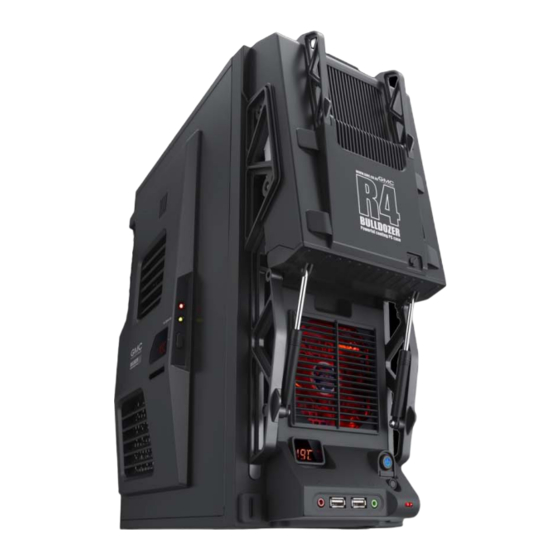
Page 4: Case Overview
Chapter 1. Product Introduction 1.3 Case Overview 3.5” bay x 2 Side Panel ODD Cover Rear 120mm fan Side panel 80mm fan 5.25” bay x 1 92mm LED fan Temperature Power switch Air filter Fan Control button Temperature Key Lock Expansion slots x 7 Front USB 2.0 / HD Audio port... - Page 5 Chapter 1. Product Introduction 1.3 Case Overview R-4 ‘Bulldozer’ has two integrated Thermometer sensors and its LED displays are located on the front and side panel. This feature is extremely good for users to monitor the PC hardware temperature according to the location of those sensors.
-
Page 6: Chapter 2. Installation
Chapter 2. Installation 2.1 Side Panel Removal 2.2 HDD Installation ① Remove the panel ① The HDD cage of R-4 thumbscrews from a side ‘Bulldozer’ is different with panel and open it by swinging normal case as well as it is it outwards. -
Page 7: Odd Installation
Chapter 2. Installation ② There 8 screws at both ③ Screw the circled part sides to mount the ODD. and attach the HDD to the drive bay. ③ Connect the appropriate power and interface connectors from 2.3 ODD Installation the power supply and motherboard to the device (IDE, S-ATA). -
Page 8: Power Supply, M/B, Graphic Card Installation
2.6 Bottom Fan Hole For the bottom panel, GMC has prepared another 80mm ventilation area for those who needs it as more airflow inside the Install the other components such as Power supply, case. -
Page 9: Case Led & Switch Connections
Chapter 2. Installation 2.7 Case LED & Switch Connections 2.8 Connecting FPIO to Mainboard ▪ Connect USB Pin to Mainboard ① Connecting wires carry the LEDs and switch connections from the LEDs and switches located behind the front bezel. The switch and LEDs connections are attached to the LEDs and switches by wires to header connectors that plugs... - Page 10 Chapter 2. Installation 2.8 Connecting FPIO to Mainboard ▪ Connect Audio Pin to Mainboard ▪ Connect Speaker Pin to Mainboard(4-pin Speaker) This connector is for a chassis-mounted front panel audio I/O module that supports either High Definition Audio or AC’97 audio standard.
-
Page 11: Front Thermometer Power Cable Connection
Chapter 2. Installation 2.9 Front thermometer power cable 2.10 Side thermometer power cable connection connection Place the thermometer Place the thermometer sensor inside of the chassis sensor inside of the chassis following user’s preference following user’s preference such as CPU, Graphic card Thermometer power Thermometer power such as CPU, Graphic card... -
Page 12: Side Fan Cable Connection
Chapter 2. Installation 2.11 Side fan cable connection Fan 3pin connector Fan controller connector...
Need help?
Do you have a question about the R-4 Bulldozer and is the answer not in the manual?
Questions and answers