Table of Contents
Advertisement
SERVICE
AIR CONDITIONER
ROOM AIR CONDITIONER
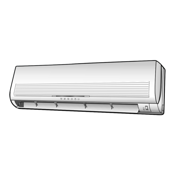
INDOOR UNIT
AQA07C5(6)ME
AQA09CA(B)ME
AQA12CA(B)ME
SH07AC5(6)
SH09ACA(B)
SH12ACA(B)
Manual
1. Precautions
2. Product Specifications
3. Operating Instructions and
Installation
4. Disassembly and Reassembly
5. Troubleshooting
6. Exploded Views and Parts List
7. Block Diagrams
8. PCB Diagrams
9. Wiring Diagrams
10. Schematic Diagrams
OUTDOOR UNIT
UQA07C5(6)ME
UQA09CA(B)ME
UQA12CA(B)ME
SH07AC5(6)X
SH09ACA(B)X
SH12ACA(B)X
CONTENTS
Advertisement
Table of Contents

Related Manuals for Samsung AQA07C5(6)ME


Summary of Contents for Samsung AQA07C5(6)ME
-
Page 1: Room Air Conditioner
ROOM AIR CONDITIONER INDOOR UNIT OUTDOOR UNIT AQA07C5(6)ME UQA07C5(6)ME AQA09CA(B)ME UQA09CA(B)ME AQA12CA(B)ME UQA12CA(B)ME SH07AC5(6) SH07AC5(6)X SH09ACA(B) SH09ACA(B)X SH12ACA(B) SH12ACA(B)X Manual SERVICE AIR CONDITIONER CONTENTS 1. Precautions 2. Product Specifications 3. Operating Instructions and Installation 4. Disassembly and Reassembly 5. Troubleshooting 6. -
Page 2: Precautions
Relocate the unit if necessary. 9. Keep children away from the unit while it is being repaired. Fig. 1-3 No Kids Nearby! 10. Be sure to clean the unit and its surround- ing area. Fig. 1-4 Clean the Unit Samsung Electronics... - Page 3 MEMO Samsung Electronics...
-
Page 4: Product Specifications
2. Product Specifications 2-1 Table AQA09CA(B)ME AQA12CA(B)ME AQA07C5(6)ME Model SH09ACA(B) SH12ACA(B) SH07AC5(6) Item Indoor unit Outdoor unit Indoor unit Outdoor unit Indoor unit Outdoor unit Type Wall-mounting Wall-mounting Wall-mounting Cooling 2.30 2.80 3.50 Dehumidifying Heating 2.35 2.90 3.80 Low temp. heating... - Page 5 2-2 Dimensions 2-2-1 Indoor Unit (Front view) Air out (Remote control) (Rear view) Installation plate Samsung Electronics...
-
Page 6: Operating Instructions And
Operating Instructions and Installation 2-2-2 Outdoor Unit UQA12CA(B)ME SH12ACA(B)X UQA09CA(B)ME SH09ACA(B)X UQA07C5(6)ME SH07AC5(6)X Samsung Electronics... -
Page 7: Pressure Graph
2-3 Pressure Graph AQA07C5(6)ME SH07AC5(6) 30.6/22.5 27/19 21.5/14.6 Outdoor drybulb temperature [deg C] AQA09CA(B)ME 30.6/22.5 SH09ACA(B) 27/19 21.5/14.6 Outdoor drybulb temperature [deg C] AQA12CA(B)ME SH12ACA(B) 30.6/22.5 27/19 21.5/14.6 Outdoor drybulb temperature [deg C] Samsung Electronics... -
Page 8: Operating Instructions
To select the 5 way function with the remote control, press the 5 way button one or more times until the desired mode is selected. Each time you press the 5 way button Each 5 way indicator on the indoor unit comes on in order. Samsung Electronics... - Page 9 De-ice end by sensing of the processing 7. FAN SPEED : Manual (3 step), Auto (4 step) time by de-ice Condition. Fan speed automatically varies depending on both the difference between setting and the room temperature. Samsung Electronics...
- Page 10 ON at a specified time using OFF TIMER : The air Conditioner is turned OFF at a specified time using *ON TIMER : Only timer LED lights on. *OFF TIMER : Both timer and operation LED lights on. Samsung Electronics...
- Page 11 It is harmful to the air conditioner if it is used in the following environments: greasy areas (including areas near machines), salty areas such as coast areas, areas where sulfuric gas is present such as hot spring areas. Contact your dealer for advice. Samsung Electronics...
-
Page 12: Installation Diagram Of Indoor Unit And Outdoor Unit
“H” metere s maximum Remote control Remote control holder Model ** 7 ** ** 9 ** ** 12 ** Piping (Liquid) 1/4" Clamper tube 7K/9K BTU Piping(Gas)3/8” Installation plate 12K BTU Installation tube Screw Vinyl tape Drain hose Putty Samsung Electronics... - Page 13 Result : All inert gas escapes from the indoor unit. • To prevent dirt or foreign objects from getting into the pipes during installation, do NOT remove the caps completely until you are ready to connect the piping. Samsung Electronics...
- Page 14 4. Pass the drain hose through the hole in the wall, making sure that it is sloping downwards, as shown in the illustrations above. The hose will be fixed permanently into position once Shield the whole installation has been tested for gas leaks; Drain hose Extension drain hose Samsung Electronics...
- Page 15 1. Insert the drain plug into the drain hole on the underside of the outdoor unit. 2. Connect the drain hose to the drain plug. 3. Ensure that the drained water runs off correctly and safely. Samsung Electronics...
- Page 16 And mount the service port cap to 3-way valve. (liquid) 7. Check for gas leakage. (gas) - At this time, especially check for gas leakage from the 3-way valve’s stem nuts, and from the service port cap. Stem cap Samsung Electronics...
- Page 17 R410A 7. Stop operation of the air conditioner. 8. Close the 3-way valve, disconnect the pressure gauge, and open the 3-way valve again. 9. Close the cap of each valve. 3-10 Samsung Electronics...
- Page 18 5~10m R410A(Add as liquid state) for every 1m. state) for every 1m. 3-2-2(i) Flare nut fixing torque Torque (kg-cm) Outer diameter Fixing Torque Final Torque ø 6.35 (Liquid Side) ø 9.52 (Gas Side) ø 12.7 (Gas Side) Samsung Electronics 3-11...
- Page 19 At this time, cover the pipe of the indoor 8. Remove the mounting plate for the indoor unit and the other pipe using a cap or vinyl unit and move it to a new location. plug to avoid foreign material entering. 3-12 Samsung Electronics...
-
Page 20: Disassembly And Reassembly
7) Pull the upper left and right of discharge softly for the outside cover to be pulled out. 8) Pull softly the lower part of discharge and push it up. Caution; Assemble the front panel and fix the hooks of left and right. Samsung Electronics... - Page 21 2) Loosen the fixing two screws and separate the motor holder. 3) Loosen the fixing screw of fan motor. (By use of M3 wrench) 4) Separate the fan motor from the fan. 5) Separate the fan from the left holder bearing. Samsung Electronics...
-
Page 22: Outdoor Unit
Handle-Cabi RH. 2) Separate the connection wire from the terminal block. 3) Loosen 6 fixing screws and separate the upper cabinet. 4) Loosen the fixing screw of Ass'y E-part. 5) Loosen 5 fixing screws and separate the side cabinet. Samsung Electronics... - Page 23 1) Do “1”, “2”, “3” above. Compressor 2) Open the terminal cover of compressor and unscrew the connection terminal. 3) Disassemble the inlet and outlet pipe of compressor by welding. 4) Loosen the three bolts of the lower part. 5) Separate the compressor. Samsung Electronics...
- Page 24 Upper. 4) Loosen two fixing screws of Ass'y E-part. 5) Loosen nine fixing screws and separate the cabi side. Fan and Motor 1) Do “1”, above. 2) Loosen four screws and seperaate Guard Fan from front cabinet Samsung Electronics...
- Page 25 3) Disassemble the inlet and outlet pipe of compressor by welding. 4) Disassemble the inlet and outlet pipe of condenser by welding 5) Loosen the three bolts of the lower part. 6) Separate the compressor. Samsung Electronics...
-
Page 26: Troubleshooting
Indoor unit heat exchanger temperature sensor Error (open or short) BIO LED blinking (1Hz) Indoor fan malfunctioning (for spead is Below 450rpm) STD, BIO and TIMER LED blinking (1Hz) EEPROM Error All LED blinking (1Hz) Option Error (option wasn’t setup or option data error) Samsung Electronics... -
Page 27: Fault Diagnosis By Symptom
Check PCB pattern. Replace ICO2 Replace main PCB. 10ms Is voltage output terminal of PC814(PC02) normal? Are voltage at #11 and #12 of the micom normal? Replace resonator (X301) 250ns Replace PC814(pc02) Is operation normal? Replace micom Samsung Electronics... - Page 28 Test rod location Normal voltage PCB CN72 Condition Fan operate about AC 180V pin #3 and #5 MF-C is out of order Replace MFC Fan motor Fan motor should be replaced. is out of order. Samsung Electronics...
-
Page 29: When The Outdoor Unit Does Not Operate. (Initial Diagnosis)
Power relay should be Is rating voltage ±10% range applied relay between Terminal block out of order replaced. NO(N1) and No. 1 Outdoor unit is out of order. Is the room sensor normal register? 10°C 20°C 30°C 17.96kΩ 12.09kΩ 8.3kΩ Samsung Electronics... - Page 30 Is the voltage between CN71 #3 and CN71 #5 rating voltage ±10% range Abnormal RY73 Abnormal 4way valve of Outdoor Unit. or connecting Cable PCB should be replaced. 4 way valve should be replaced or connecting Cable Check. Samsung Electronics...
-
Page 31: Samsung Electronics
Voltage at PIN #30 of Remocon Micom change? Voltage at collecter of Q601 or Q602 change? Q601(C4375Y) or Q602(C1623Y) is faulty. IR LED(CL-1L5EU) is faulty. Voltage at pin #26 of micom (IC04) change (INDOOR UNIT)? Receiver module is faulty. Micom (IC04) is faulty. Samsung Electronics... - Page 32 5-3-2 Procedure The parts should be replaced in the following procedure. Check for any faulty part. Detach the faulty part. Replace it with a new part. Check the operation of the new part. The repair is completed. Samsung Electronics...
- Page 33 Voltage check SMPS circuit is faulty 1. check voltage of IC06 IC06 is faulty (pin#10,pin#8) Set the TURBO mode : relay on 0.7[v] : relay off 12[v] 2. Voltage at terminal block RY71 is faulty ((N1) -1) rating voltage Samsung Electronics...
-
Page 34: Fault Diagnosis Of Major Parts
350Ω ±10% 340Ω ±10% 340Ω ±10% Out Power ∞, OΩ … open or short Abnormal Measure resistance between red wire and each terminal. Normal Approx. 300Ω at ambient temperature (20°C ~30°C) ∞, OΩ … open or short Abnormal Samsung Electronics... - Page 35 $ When pressing the button appear on the display, select one of them. % When pressing the button appear on the display, select one of them. ^ When pressing the button appear on the display, select one of them. 5-10 Samsung Electronics...
- Page 36 If all lamps of indoor unit are flickering, Plug out and plug in again and pressing ON/OFF key to retry. If the unit is not working properly or all lamps are continuously flickering after setting the option code, see if the correct option code is set up for it’s model. Samsung Electronics 5-11...
- Page 37 Troubleshooting <Table of the option code> OPTION CODE MODEL AQA12CAME 016CA6-170340 SH12ACA AQA12CBME 006CA6-170340 SH12ACB AQA09CAME 016A25-1700FC SH09ACA AQA09CBME 006A25-1700FC SH09ACB AQA07C5ME 015825-1700C8 SH07AC5 AQA07C6ME 005825-1700C8 SH07AC6 5-12 Samsung Electronics...
- Page 38 MEMO Samsung Electronics 5-13...
-
Page 39: Exploded Views And Parts List
6. Exploded Views and Parts List 6-1 Indoor Unit 20-6 20-6-1 20-1 20-7 20-4 20-5 20-3 20-2 13-2 13-3 13-4 13-1 You can search for the updated part code number through the ITSELF. URL : http://itself.sec.samsung.co.kr Samsung Electronics... - Page 40 Exploded Views and Parts List Parts List Q’TY Description REMARK CODE NO AQA12CA(B)ME AQA09CA(B)ME AQA07C5(6)ME SH12ACA(B) SH09ACA(B) SH07AC5(6) DB64-00354A GRILLE AIR INLET DB63-00064A GUARD-AIR FILTER DB95-00287G FILTER CLEANER ASS´Y DB63-00067A COVER TEMINAL DB92-00248A ASS´Y PANEL DB67-00051A SPACER EVAP LOW DB67-00032A...
- Page 41 6-2 Outdoor Unit • UQA12CA(B)ME • SH12ACA(B)X • UQA09CA(B)ME • SH09ACA(B)X Samsung Electronics...
- Page 42 ASS´Y CHECK V/V ASS’Y(1.42x900/1.42x600) DB99-00157B ASS´Y CAPILLARY ASS’Y (1.3x800) DB96-01461A ASS´Y COND ASS’Y(SF) DB96-00798A ASS´Y COND ASS’Y(SF) DB90-00634A CABINET SIDE ASS’Y(BENDING) DB63-10443C HANDLE CABI, RH DB61-00802A BRACKET MOTOR SGCC-M, T1.2 DB72-00683A CLOTH COMP T10.0 DB72-00689B CLOTH COMP T10.0 Samsung Electronics...
- Page 43 Outdoor Unit • UQA07C5(6)ME • SH07AC5(6)X Samsung Electronics...
- Page 44 ASS´Y TUBE CAPILLARY ASS´Y 17-1 DB62-00897A VALVE-SERVICE 1/4”, HFC DB99-00194A ASS´Y VALVE 4WAY ASS´Y 18-1 DB62-00815A TUBE-4WAY VALVE VK1400B 18-2 DB62-00896A VALVE-SERVICE 3/8”, HFC DB96-01286A ASS´Y COND 1.5 LOUVER DB64-60171C CABINET-SIDE SECC-P, T 0.8, A-P/J DB63-01069E COVER-E, PARTS ASS’Y SC-90073R Samsung Electronics...
- Page 45 6-3 Remote Control & PCB Box 6-3-1 ASS'Y REMOCON : DB93-00251L Parts List Description Q’TY Remark INLAY LCD CASE TOP KEY RUBBER ASS’Y PCB REMOCON CASE LOW BATTERY COVER Samsung Electronics...
- Page 46 ASS’Y ASS’Y TERMINAL BLOCK ASS’Y DISPLAY PCB ASS’Y CONNECTOR WIRE PCB U/D HOLDER WIRE CLAMP SCREW PH, M3 5 L22 SCREW TH + M4 5 x16, ZPC(WHT), SWRCH HOLDER CLAMP IN SEAL PANEL FRONT RH SEAL H/CONTROL FRONT Samsung Electronics...
- Page 47 MEMO Samsung Electronics...
-
Page 48: Block Diagrams
7. Block Diagrams 7-1 Refrigerating Cycle Block Diagram Note - The check valve is applied only to UQA12CA(B)ME/SH12ACB(X) as below UQA12CA(B)ME Note Samsung Electronics... -
Page 49: Pcb Diagrams
8. PCB Diagrams 8-1 ASS’Y MAIN PCB TOP PATTERN Samsung Electronics... - Page 50 R402 R-CHIP MCR10EZHJ472 R108, R603, R901 R-CHIP MCR10EZHJ102 R201, R207, R208, R301, R401, R403, R408, R601, R607, R608 R-CHIP MCR10EZHJ561 R606 R-CHIP MCR10EZHJ471 R105, R604, R605 R-CHIP MCR10EZHJ331 R405, R407 R-CHIP MCR10EZHJ221 R106, R107 RELAY-MINIATURE F3AA012E RY72, RY73 Samsung Electronics...
- Page 51 8-2 ASS’Y MAIN PCB; DB93-00437A BOTTOM PATTERN Samsung Electronics...
- Page 52 MODULE REMOCON RM01 KSM-713TH5 TACT SWITCH SW01 KPT-1105A C-CERAMIC 102K C-CERAMIC 104Z DIODE SWITCHING IN4148 R-CARBON R01, R02, R03 470 1/2W 5% JUMP 10mm CONNECTOR WAFER CN02 SMAW200-05 CONNECTOR WIRE CN01 UL1007, AWG#26 8-4 ASS’Y CENTER DISPLAY; DB93-00859A Samsung Electronics...
- Page 53 MEMO Samsung Electronics...
-
Page 54: Wiring Diagrams
9. Wiring Diagrams 9-1 Indoor Unit Samsung Electronics... - Page 55 9-2 Outdoor Unit • UQA12CA(B)ME SH12ACA(B)X • UQA09CA(B)ME SH09ACA(B)X • UQA07C5(6)ME SH07AC5(6)X DIAGRAM-OUTDOOR C1 : MOTOR CAPACITOR C2 : COMP CAPACITOR Samsung Electronics...
- Page 56 MEMO Samsung Electronics...
-
Page 57: Schematic Diagrams
10. Schematic Diagrams 10-1 Indoor Unit 10-1 Samsung Electronics Samsung Electronics 10-2... - Page 58 MEMO 10-3 Samsung Electronics...
- Page 59 Itself Solution Integrated technology supporting electronic library http://itself.sec.samsung.co.kr Copyright © 2002 By Samsung Electronics Co., Ltd. All rights reserved. This manual may not, in whole or in part, be copied, photocopied, reproduced, translated, or converted to any electronic or machine readable from without prior written permission of Samsung Electronics Co., Ltd.
- Page 60 ELECTRONICS © Samsung Electronics Co., Ltd. Apr. 2002. Printed in Korea. Code No. DB98-04444A(1)