Thermolec acu-steam User Manual
Hide thumbs
Also See for acu-steam:
- User and maintenance manual (34 pages) ,
- User and maintenance manual (32 pages)
Table of Contents
Advertisement
User and Maintenance Manual
for the Homeowner
and
Installation Instructions
for the Contractor
ACU-STEAM™ Humidifi er
by Thermolec
A
CU STEAM
!
Please read this manual carefully before beginning installation.
Important Notice to the Contractor :
Once the installation is complete, please leave this manual with the customer for future reference.
JANUARY 2014 V2.0 US
Advertisement
Table of Contents

Related Manuals for Thermolec acu-steam


Summary of Contents for Thermolec acu-steam
- Page 1 User and Maintenance Manual for the Homeowner Installation Instructions for the Contractor ACU-STEAM™ Humidifi er by Thermolec CU STEAM Please read this manual carefully before beginning installation. Important Notice to the Contractor : Once the installation is complete, please leave this manual with the customer for future reference.
- Page 3 The manufacturer will assume no responsibility and the warranty will be void if the installer or the user does not adhere to the following precautions/recommendations : Water quality and hardness can signifi cantly affect the maintenance frequency of your Acu-Steam humidifi er. If the cold water supply as measured by grains per gallon (gpg) exceeds 7.0 gpg, the water is classifi...
-
Page 4: View Of The Unit
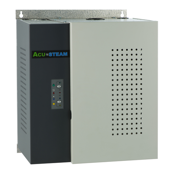
Instructions and User Manual for the Homeowner View of the unit Fig. 2a External view of the humidifi er. CU STEAM Water Tank Top View. Please see Fig. 2b. Fig. 2b Water tank Side View. Please see Fig. 2c. *Acu-15 model has two steam outlets Fig. - Page 5 A humidistat (installed either on the wall or the air return duct) controls the unit. You set the knob of the humidistat according to your desired level of humidity (35-45% recommended). Please read the next section about the Acu-Steam humidity control. When the humidistat senses a need for humidity, it starts the humidifi cation process.
- Page 6 If you installed an ACU-STEAM humidistat and an outdoor sensor, this adjustment will be done automatically through a function called outdoor reset. The outdoor sensor automatically reduces the humidistat setting according to the outdoor temperature during cold days;...
- Page 7 - Yellow Fig. 5a The ACU-STEAM humidistat also has two pilot lights to indicate the current status. The green light is lit when the humidistat is demanding for humidity, thus activating the boiling cycle. The red light indicates a warning and reproduces the same warning code as the red light on the humidifi er control panel.
- Page 8 Warning Red light An abnormal condition occurred. Please refer to the error code table in Section 7. Steam White light The humidifi er is heating water to produce steam. Filling cycle Blue light The electric water valve is open thus fi lling the humidifi...
-
Page 9: What To Do If A Malfunction Occurs
What To Do if a Malfunction Occurs Shut the main power OFF and restart the humidifi er to see if the error code (fl ashing red light) disappears. If you see a water leak, follow the water supply tube and close the valve installed on the water pipe located near the humidifi... -
Page 10: Maintenance
(see section 18.5 for drain cycle settings). First turn down the humidistat to avoid a steam cycle. Please note that when using an ACU-STEAM electronic humidistat, if the relative humidity is extremely low the humidifi er may still run with the knob at the minimum setting because of a range limiter inside the cover. - Page 11 DO NOT use any acids when cleaning your Acu-Steam humidifi er. Once completed, reinstall the o-ring gasket around the bottom tank collar. Please see Fig. 8b. Align the two arrows located at the front of the tank and the fi...
- Page 12 Put the overfl ow pan under the tank by sliding the slot on the back screw and hooking the key hole on the front screw. 8.10 Reconnect the white wire of the overfl ow sensor on the overfl ow pan. 8.11 Put the overfl...
-
Page 13: Preventative Maintenance
Preventative Maintenance In order to avoid problems due to accumulation of deposits, we suggest that you replace the silicone drain tube and the low and high water level sensors every 2 to 4 years. We also suggest you replace the round o-ring gasket around the tank. -
Page 14: Warranty
Thermolec’s written consent, voids the warranty. 10.4 All defective parts must be claimed within the warranty coverage period and shall be replaced at no charge (transport included) by Thermolec. Thermolec does not cover the labor costs to execute the said repairs. 10.5 Thermolec will not be held responsible for accidental or consequential damages, nor for operational delays caused by the replacement of said steam humidifi... -
Page 15: Unpacking The Unit
Detailed Instructions for the Contractor Unpacking the Unit 11.1 Contents Please inspect the carton’s contents and report any missing parts or damage immediately. 1 ea Humidifi er 1 ea Main siphon tube (32” long – already installed and coiled inside the unit) 1 ea Steam hose (4 feet long x 1 inch I.D.) / 2 ea Steam hoses for Acu-15 1 ea Steam diffuser (12”... - Page 16 Dimensions and Available Models Fig. 12a 12.1 Humidifi er dimensions 11 5/8” CU STEAM 14” 9” 13” Fig. 12b 12.2 Available models Capacity Model Lbs/Hr Power Voltage Current (Kg/Hr) (Kw) Acu-5U (2.2) 12.5 Acu-10U (4.4) 12.5 12.8 Acu-15U (5.9) 16.6 Page 14...
- Page 17 Detailed View and Wiring Fig. 13a View of the top of the unit. Electric Black Steam Outlet Valve Heating Element Black Acu-15 model has two steam outlets High Level Low Level Level Sensors Yellow Manual Thermal Cut-out White Green Blue Blue Overflow Pan White...
- Page 18 View and list of the wire harness by color and function. Please see Fig. 13b & Fig. 13c. Overflow Sensor Ground connection connection On/Standby LED On/Standby Element Switch Relay Fan LED Neutral Alarm LED Fuse connection Steam LED Fill LED Transformer Relay 1 2 3...
- Page 19 Note: Please read sections 14 and 15 before proceeding. Installing the Steam Diffuser and the Steam Hose 14.1 Proper installation of the diffuser and steam hose is critical for the trouble-free operation of the humidifi er. Please fi nd an accessible location on the duct and make sure you have a minimum length of 35”...
- Page 20 14.3 Install one end of the steam hose onto the steam diffuser using a hose clamp and tighten it. 14.4 After installing the humidifi er (Section 15) use the second supplied hose clamp, to install the other end of the steam hose (4 feet long) onto the steam outlet on the top of the water tank and tighten it. Never try to reduce the diameter of the steam hose or any added rigid piping.
-
Page 21: Installing The Humidifi Er
Installing the Humidifi er For ease of service, keep a minimum space of 24” in front of the unit. 15.1 Remove both covers by fi rst turning the 1/4 turn screw to the left and swing open the tank cover and unhook it. - Page 22 15.5 A rigid drain pipe has to be installed under the unit and connected to the main house drain. We recommend a 1” minimum I.D. tube or standard 1-1/2” I.D. ABS plumbing tube to do the installation. Please also install a siphon (P-trap) with a drain cap, if required. The two fl...
- Page 23 We recommend installing a quarter of a turn shut off valve (not supplied) near the unit. This supply valve (not supplied) must be attached to a cold water pipe only, easily accessable from the Acu-Steam unit. Since the unit is draining hot water, cold water is added to reduce the temperature before sending the water to the drain.
- Page 24 16.5 Cut the two drain tubes and insert them in the rigid pipe. Note that the main silicon drain tube must have a minimum length of 18” to allow the siphon to work properly. It is important to leave an air gap between the soft tubes and the rigid pipe.
- Page 25 Installing the Air Pressure Probe 17.1 The pressure probe (also called a Pitot tube) connected to the pressure differential switch inside the unit checks whether there is enough air pressure in the warm air duct to activate the humidifi er. 17.2 The probe can be installed in either the warm air or cold air return duct, as close as possible to the humidifi...
-
Page 26: Making Electrical Connections
Making Electrical Connections NOTE : All internal wiring is done at the factory. All external wiring shall be done by a qualifi ed electrician and must conform to procedures, regulations and local codes. 18.1 A dedicated breaker in the main panel (or fused disconnect) must be installed. 18.2 Ensure that the wire size and protection equipment conform to the sizes required by the Electrical Code. - Page 27 (see page 4, sections 4.1 through 4.5 explain the functions of the Acu-Steam wall and duct humidistats). If you decide to use a standard mechanical humidistat by others, connect the mechanical humidistat between the terminals marked GND (ground) &...
-
Page 28: Start-Up And Test Procedure
Start-up and Test Procedure 20.1 Turn the breaker “ON” to supply power to the humidifi er. The green light comes ON to confi rm that the unit is ready to work. 20.2 Test of the On/Standby button. Press the white button once. The green light goes OFF then fl ashes, indicating that the unit is in standby mode but still powered. - Page 29 NOTE: The Acu-Steam board has a memory that remembers the last sequence of operation when the power is turned off, hence the unit might start at step 2 or 3 when you put the power back on. Also, timings may slightly vary depending on the capacity of the unit (1.5 kW, 3 kW or 4 kW), the pressure of the water inlet and the quality of...
-
Page 30: Wiring Diagrams
Wiring diagrams Page 28... - Page 31 120VAC Page 29...
- Page 32 Page 30...
-
Page 33: Detailed Error Codes
Detailed Error Codes Page 31... - Page 35 CU STEAM ® S-15 ELECTRONIC HUMIDISTAT AND OUTDOOR SENSOR INSTALLATION INSTRUCTIONS Jan. 2008 - V1.2...
-
Page 36: Specifications
ACU-STEAM HUMIDISTAT, version A Features State of Art digital RH sensor ROOM or DUCT mounting Reprogrammable Microcontroller Potentiometer Set-point setting Out-door temperature sensor for Set-point Reset Green (ON/OFF) and Red (warning) status LEDs Specifi cations Set-point range. - Page 37 Installing and Connecting the ACU-STEAM Humidistat and the Outdoor Sensor The humidity sensor is not located at the same place in a wall mount or in a duct mount humidistat and therefore the two models of humidistats are not interchangeable. Please see Fig.1a and Fig.1b.
- Page 38 To force a drain cycle when the humidifi er is running and producing steam, simply turn down the humidistat. Please note that when using an ACU-STEAM electronic humidistat, if the relative humidity is extremely low the humidifi er may still run with the knob at the minimum setting because of a range limiter inside the cover.
- Page 39 DRILLING TEMPLATE FOR DUCT MOUNT HUMIDISTAT 5/8” dia.
Need help?
Do you have a question about the acu-steam and is the answer not in the manual?
Questions and answers
I have been advised to purchas as a replacement ACU Steam 5-I **** concerned how to wash the Filters--would this machine have the same filters as the unit being replaced{Generalaire Brand name}