
Related Manuals for CUSHCRAFT MA5B


Summary of Contents for CUSHCRAFT MA5B
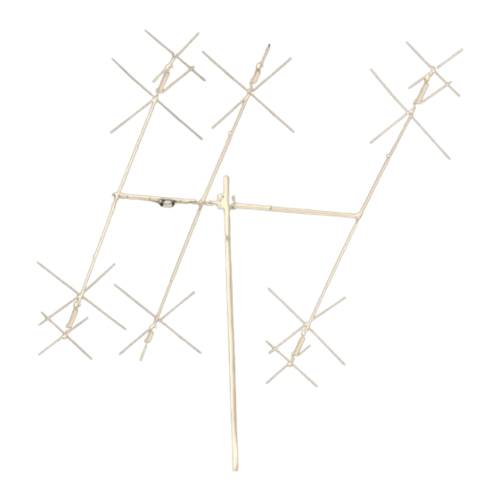
- Page 1 ASSEMBLY AND INSTALLATION INSTRUCTIONS MA5B 20 / 17 / 15 / 12 / 10 Meter Beam Antenna 951485 (5/99)
- Page 2 TUNING PROCEDURE Set the element lengths for the portion of the band you want to operate on using Chart A and Figure 2. Your MA5B is now ready for use. You may check the VSWR in order to confirm assembly was done properly. The easiest place to check the antenna is likely to be in its final mounting configuration.
-
Page 3: Master Parts List
MA5B ELEMENT EE (7/8” x 12”) MA5BED MA5B ELEMENT ED (1-1/8” x 46”) MA5BEC MA5B ELEMENT EC (7/8” x 7”) MA5BEB MA5B ELEMENT EB (1-7/8” x 36” SW) MA5BEA MA5B ELEMENT EA (1-1/8” x 34”) MA5BBB MA5B BOOM BB (1-5/8” x 24”) MA5BBA MA5B BOOM BA (1-1/2”... -
Page 4: Boom Assembly
MA5B 1 - BOOM ASSEMBLY Place the worm clamps (413) over the slotted ends of tube BB. Slide DISPLAY DESC SIZE both BA sections into BB as shown in Figure 1. Each BA section 010118 SS Hex Nut 5/16-18 should be inserted 12 inches (30.5 cm) into section BB to leave 32 inches (81.3 cm) exposed on each end. -
Page 5: Element Assembly
MA5B 2 Element Assembly DISPLAY DESC SIZE Assemble the elements per Figure 2. To assemble element #1, insert 010011 SS HEX NUT 8-32 the Fiberglass insulator (98) into element sections EA and align the outer holes of the insulator with the holes in section EA. Place the 8-... - Page 6 MA5B ELEMENT ASSEMBLY Cont. FIGURE 2 ELEMENT #3 2 PLACES 4” 4” (10.2 cm) (10.2 cm) 205.5” (522 cm) ELEMENT #2 2 PLACES 5” 5” (12.7 cm) (12.7 cm) ELEMENT #1 2 PLACES 4” 4” (10.2 cm) (10.2 cm) 2 PLACES FREQUENCY DIM.
- Page 7 MA5B DISPLAY DESC SIZE 3-X-HAT ASSEMBLY 010011 SS HEX NUT 8-32 190026 ELEMENT 7/8" x 7/8” Raise each element assembly off the ground to attach the X-hats to the BRACKET (.2.2 x 2.2 cm) elements. For element #1, place the 41-inch X-hat rods (X41) and element brackets (26) on elements EB as shown in Figure 3B.
- Page 8 MA5B 4 - ELEMENT MOUNTING DISPLAY DESC SIZE Attach the elements to the boom assembly as shown in Figure 4. Attach 190033 BACKING 1” x 3-1/2” element #1 to the end of the boom at 36 inches from the mast clamp.
- Page 9 MA5B FIGURE 4A 4 - ELEMENT MOUNTING Cont. Boom FIGURE 4B Element #1 Boom Boom 2 PLACES 2 PLACES Element #2 FIGURE 4C Boom 2 PLACES 2 PLACES Element #3 2 PLACES 2 PLACES Page 8...
-
Page 10: Matching Network
MA5B 5 - MATCHING NETWORK DISPLAY DESC SIZE 010011 #8-32 Install the matching network (MN) to the boom as shown in Figure 5. Loosely attach the worm clamps (413) around the brackets on the matching network and boom section. Attach the feed wires to elements... - Page 11 MA5B 6 - BOOM TO MAST ASSEMBLY DISPLAY DESC SIZE Before installing the antenna on the mast, check all hardware and worm 010118 HEX NUT 5/16" clamps to insure they are tight. Install the antenna on the mast as shown...
-
Page 12: Specifications
Cushcraft, any such antenna is defective, then Cushcraft Corporation will, at its option, repair or replace the antenna at its expense within thirty days of the date the antenna is returned (at purchasers expense) to Cushcraft or one of its authorized representatives.
Need help?
Do you have a question about the MA5B and is the answer not in the manual?
Questions and answers