Table of Contents
Advertisement
Quick Links
Advertisement
Table of Contents
Troubleshooting

Related Manuals for Winegard 2-WAY SATELLITE INTERNET SYSTEM


Summary of Contents for Winegard 2-WAY SATELLITE INTERNET SYSTEM
- Page 1 WINEGARD 2-WAY SATELLITE INTERNET SYSTEM PRODUCT MANUAL This Document Contains Confidential & Proprietary Information Winegard Company 3111 Kirkwood St. Burlington, IA 52601 877-704-1112 Printed in USA ©2011 Winegard Company www.winegard.com 7451014 | Rev1 12-13...
- Page 2 This document is intended for use by trained service technicians. All companies and service personnel using this document must have a signed non-disclosure agreement on file with Winegard Company. For information on how to obtain a non-disclosure agreement from Winegard Company please support@winegard.com contact either or call 877-704-1112.
-
Page 3: Table Of Contents
1. SCOPE ......................5 2. WARNINGS AND HAZARDS ................5 2.1. How To ..............................9 3. AGENCY CERTIFICATIONS................. 13 4. GENERAL DESCRIPTION ................15 5. WX SERIES DESCRIPTION & INSTALLATION ........... 16 5.1 Antenna Mount - Main Assemblies .....................16 5.2 WX Installation Information .......................17 6. - Page 4 8.5 - Search Routine Flowchart ........................71 8.6 - Troubleshooting...........................72 8.7 - Motor Controls ............................74 8.8 - Communications ..........................79 9. REFERENCE MATERIALS ................80 9.1 - Upper and Lower case TRK .......................80 9.2 - Null Modem ............................80 9.3 - On-Screen Keypad (Windows CE) ....................80 9.4 - Wiring Diagram ..........................81 10.
-
Page 5: Scope
1. Scope The purpose of this document is to provide Installers, Technicians and End Users with a complete Winegard 2-Way Product manual which fulfills the roles of an Installation Manual, Operation Manual and Service Manual. 2. Warnings and Hazards Automated Machinery – The outdoor antenna system may start moving Caution –... - Page 6 Warning – Pinch Hazard, Bodily Injury Hazard – Antenna support and lift mechanism. Keep hands and other body parts away. Warning – Pinch Hazard, Bodily Injury Hazard – Rotating feed horn, polarizer mechanism. Keep hands and other body parts away. P a g e...
- Page 7 Warning – Pinch Hazard, Crush from Above, Bodily Injury Hazard – Skew (polarizer) assembly, feed arms and mounting brackets. Keep hands and other body parts away. Warning – Pinch Hazard, Crush from Above, Bodily Injury Hazard – Antenna support brackets. Keep hands and other body parts away. P a g e...
- Page 8 Warning – Pinch Hazard, Crush from Above, Bodily Injury Hazard – Antenna support brackets. Keep hands and other body parts away. P a g e...
-
Page 9: How To
2.1. How To 1. Unpack system and remove pallet. 2. Unlatch the lid hold down brackets on either end of the skid as shown below. P a g e... - Page 10 3. Open lids on both sides as shown below. P a g e...
- Page 11 4. Remove the IDU case from the inside of the skid before making any movements. Open the IDU case, remove the controller, and make the appropriate connections. Use the case to store the latch straps, but do not store the case inside the skid at any time except when stowing the unit for transportation.
- Page 12 5. Open the reel door and latch secure as shown below. 6. Disconnect the three cable connectors (red, yellow, and blue) from the side of the drum (as shown below) using the provided wrench prior to unrolling the cables. Reconnect all three cables after cable has been reeled out to a sufficient length. P a g e...
-
Page 13: Agency Certifications
3. Agency Certifications FCC Part 15 Class B The following model(s) have been tested and found to be in compliance with Part 15 of the FCC rules for class B devices. Operation of these devices is subject to the following two conditions: (1) This device may not cause harmful interference, and (2) this device must accept any interference received, including interference that may cause undesired operation. - Page 14 In Door Unit The Winegard In Door Electronics, or IDU, refers to the 2-Way Controller. The term IDU does not include the user supplied modem or Ethernet distribution system. Interchangeable words in the industry: Controller Out Door Unit The Winegard Out Door Electronics, or ODU, refers to the electronics manufactured by Winegard which are located on the antenna itself.
-
Page 15: General Description
The WX antenna system consist of a high wind resistant mechanical antenna, Out Door Unit (ODU) and all wiring and motors required to point the system using the Winegard 2- Way Controller. The model numbers for the appropriate controllers are 7750188 (TNC connector) and 7750190 (F connector). -
Page 16: Wx Series Description & Installation
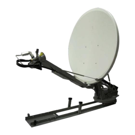
5. WX Series Description & Installation 5.1 Antenna Mount - Main Assemblies 7. Reflector - The WX1200 and WX980 antennas use a Prodelin reflector. 8. Elevation Actuator - The elevation actuator is attached to the Reflector back plate and Main Drive Mechanism 9. -
Page 17: Wx Installation Information
5.2 WX Installation Information The Winegard WX antenna should be mounted to a secure platform using the rails provided. The following diagrams show the mounting point dimensions as well as the wiring panel at the base of the antenna. 1. Mounting points - All mounting points should be connected to a cross member or secure mounting point on the vehicle roof or mobile platform. - Page 18 3. Max Clearances - The Max Horizontal and Vertical clearances should be considered when deciding where to install the antenna. P a g e...
- Page 19 P a g e...
- Page 20 Elevation Clearances – Due to the different elevation clearances inherent in the design of the OPT1038 skid option, please follow the guidelines in the drawing below to pre-point the skid system prior to deployment depending on the necessary elevation clearance for the location where the system is being deployed.
- Page 21 Examples – If the location where the system is being deployed requires an elevation look angle of 18 degrees, then this would fall in the range of elevation in Section B, which has a range of 240 degrees of azimuth sweep (±120 degrees from the stowed position).
-
Page 22: Controller Description & Configuration
The Controller is a state of the art system capable of connecting to and pointing any of Winegard’s auto deploy satellite Internet antennas. The IDU controller is the central decision making center in the Winegard 2-Way Satellite Communications System. The Controller sends commands to the ODU, which in turn moves the motors and keeps records of the motor counts, states etc. -
Page 23: Front Panel Connections & Interfaces
6.1 - Front Panel Connections & Interfaces The front panel of the controller contains the following components: 1. Power Button - The Power Button is dark when the controller is in stand by and will illuminate bright green when the controller is powered on. This button does not completely shut power off when in stand by mode. -
Page 24: Rear Panel Connections
Connection for a remote status indicator. 8. Fuse - 5A 32V Fast Acting Type ATF Winegard P/N 2320020 9. Model/Serial Number Label This label contains the model number a serial number of the IDU. This label contains logos for all agency certifications. -
Page 25: Main Menu Interface Screen
6.3 - Main Menu Interface Screen The Winegard 2-Way Controller’s Main Menu Interface Screen is the primary means for deploying, re-peaking and stowing the system. It provides links at the top of the screen to the Authorized Installer menu (yellow triangle) for configuration of the system as well as the Advanced User Data section (wrench) to see live data, network configuration and firmware update screen. -
Page 26: Configuration
Winegard antenna systems without the need for additional configuration. Also, communication with modems from other manufacturers to provide a fully integrated system is a feature of the 2-Way controller software. 6.4.1 - Network Configuration The first step in the configuration process is setting up the network parameters of the controller. - Page 27 5. NETWORK SETUP screen - At the top of the NETWORK SETUP screen the header section details if the Network Adapter is currently in DHCP or STATIC mode. 6. Versions 8.0.0.0 and later of the firmware allow configuration of the network adapter from here.
- Page 28 If an incorrect value is entered, the DEL button will backspace one character per tap. 10. Once all network configuration information has been entered and verified, tap on the “MAIN MENU” button at the bottom of the NETWORK SETUP screen to exit to the main menu.
- Page 29 6.4.2 - Configuring the Controller Configuring the Winegard Controller is a rather simple process which is based on two sections of configuration that run concurrently. The first section consists of question screens asking if the user wants to move the antenna or perform calibrations and the second section is primarily centered around the modem and service parameters for the search.
- Page 30 3. ENTER PASSCODE screen - The next screen that appears is a numerical pad requesting input of the Passcode. The Passcode is set from the factory to a default of “1234”. If an incorrect value is entered, the DEL button will allow you to backspace one character per tap.
- Page 31 The RECEIVE SIGNAL screen allows for manual jogging of the antenna for assembly, wiring and even pointing purposes used in testing. However, if in Generic mode, please note that after movements are accomplished in this screen the only choice available is to tap on the “NEXT” button which will then require that the system is stowed.
- Page 32 If you select “No” you will be returned to the Main Menu. If you select “Yes” the following screen will appear: The EMERGENCY screen allows for manual movement of the antenna intended for Emergency stowing if for some reason the system is stowing in the incorrect azimuth location.
- Page 33 6. CALIBRATION screen - This screen will state that a calibration is not required and this is usually the case since a calibration was performed at the factory prior to shipping. If you select “No” you will be taken to the CALIBRATE COMPASS screen on item If you select “Yes”...
- Page 34 The “GO” button will change to a “STOP” button and the “NEXT” button will become grayed out. The Controller will tell the ODU to move the antenna motors in all axis sequentially, first elevation, then skew and finally azimuth before stowing the antenna. iii.
- Page 35 If the system is in Compass mode, then the following screen will appear. Select “SKIP” to move to the COMPASS HEADING screen where you will select “NEXT” to continue to step 8. P a g e...
- Page 36 8. After completing the Compass Heading and Calibration screens on the previous page, the controller will advance to the ADVANCED OP MODE screen. In this screen there are only two modes which are supported for field deployment, Normal Search Mode and Inclined Orbit Search Mode. Both modes handle the acquisition of a satellite in the same manner but perform different functions after the acquisition.
- Page 37 Select “iDirect” and tap the “NEXT” button, the following screen appears: Next choose either Modem or DVB search option. Winegard recommends that you always select “MODEM” if interfaced to a modem which is available on our MODEM SELECTION list but there may be times when “DVB”...
- Page 38 MODEM Search - The controller searches for the target satellite based on feedback from the modem for carrier acquisition and carrier SNR. This mode has a larger search window and moves across the Azimuth plane at a slower rate. Notice that the use of a PLL LNB is required when performing a MODEM search. DVB Search - The controller searches for the target satellite based on feedback from our internal tuner frequency and symbol rate lock.
- Page 39 Once you tap the parameter section of the previous screen you will move to the input screen. On this screen you can tap on each section in white to change the values. Numeric sections will bring up a number pad to input the longitude. After input of the longitude data, the “NEXT”...
- Page 40 The AUTO PEAK screen asks if you would like to turn on AUTO PEAKING. If Auto Peaking has not been turned on before, then the default is from the factory. Auto Peaking is available on all selections except for HughesNet and Generic, and is at the discretion of the installer.
- Page 41 The default Auto Peak values are: Interval = 60 minutes SNR Threshold = 0.5 dB Axis Movement = AZ 0.3, 2.0, 0.5 EL 0.3, 1.2 Due to the condensed nature of this manual, do not make changes to the Auto Peak values at this time.
- Page 42 10. Final configuration notes - The controller is now configured to work with the iDirect modem selected for this install. As stated earlier, prior to deployment, the installer should Verify and Calibrate Compass heading which is covered in the next section. P a g e...
- Page 43 6.5 - Compass Screen & Calibration The Winegard antenna has a built in Compass which may need to be calibrated for optimal performance. In the case of all WX, DS and DT antennas, the Compass Calibration requires a complete 360⁰ to 720⁰ turn of the platform which the antenna is installed.
- Page 44 The HEADING screen changes some of its information depending on the current Heading mode. 1. HEADING SCREEN (Compass Mode) - Notice the CALIB button is enabled and the mode next to the MODE toggle button shows COMPASS. The wording, above the MODE button, states that a Compass Calibration is currently required and the True Heading display shows a very accurate heading.
- Page 45 6.5.2 - How to Calibrate the Compass Tap the heading display below the Compass Mode output in the Main Menu. The controller will enter the HEADING screen. Look at the Compass Mode and choose a path below: If the controller is currently set to COMPASS mode, proceed to step 3. If the controller is currently set to FIXED Heading mode then tap the “MODE”...
- Page 46 screen that appears next will depend on the type of antenna the controller is connected to. The way a calibration is performed is handled differently between a WX, DS and DT antenna and a SPA and FA type antenna. On either event, the calibration’s first section shows a live compass heading and states that if the heading is not within 15 degrees of actual magnetic heading, then a calibration will need to be performed.
- Page 47 Move the vehicle in a 360 to 720 degree circle in a large area and watch the compass live output until it begins to reflect the correct heading compared to your hand held compass. The “STOP” button simply stops the calibration and the moving arrows.
- Page 48 This will set the True and Rough headings to the correct heading. Alternately you can also tap on the true heading display and enter an exact heading value. Unlike calibrating the compass, the Fixed heading process works the same for all Winegard antennas. P a g e...
- Page 49 This will tell the system to use the entered value above to make the calculation of the target satellite vector. 4. After the correct direction is set, press the “DONE” button to return to the Main Screen. Compass override is complete. 5.
-
Page 50: Advanced User Data
6.6 - Advanced User Data The Advanced User menu is denoted by the Wrench Icon on the Main screen. Here the controller displays sensor data, network information, software versions and allows for calibration of the motors and updating of the firmware. In the Advanced User Data screens, pressing the Main Menu will take you out of the Advanced User Data section and return to the Main Screen. - Page 51 GPS STATISTICS screen - The GPS STATISTICS screen displays GPS data. The heading will display either (Live) or (Saved) depending on the state of the GPS input. If GPS acquisition was not able to complete (indoors, etc) the system would ask at boot time if the user wants to use Saved coordinates.
- Page 52 NETWORK SETUP screen - The Network setup is better described in the configuration section on page 16. Select “NEXT” to advance. VERSIONS screen - The VERSIONS screen displays current software for both the Controller (IDU) and Outdoor Electronics (ODU). Please see the Reference section for listing of software versions and System ID information.
- Page 53 UPDATE screen - The UPDATE screen allows the user to either update the firmware on the Controller and ODU or access the configuration reset screen. The Automatic button is always grayed out and the heading on this screen has the added (Manual) header.
- Page 54 UPDATE NOW - Selecting the UPDATE NOW button, from the “UPDATE” screen, displays the screen below. “CANCEL” will return the user to the UPDATE screen. “UPDATE” takes you to the following screen: This screen allows the user to back out of the firmware update by selecting “NEXT”.
-
Page 55: Operation
7. Operation The Controller’s main functions, such as deployment, re-peaking and stowing are handled at the Main Screen. The controller will display button options dependent on the current state of the antenna and conditions. Find Satellite is only available when the antenna is stowed or the controller has been rebooted but a carrier is not present. - Page 56 P a g e...
- Page 57 Once power to the transmitter has been verified to be disabled, the antenna will begin rising in elevation. The screen below shows the antenna deploying to the calculated coordinates. The controller will move and test the calculated location for a modem lock. If a lock is found at that location, the controller will begin to peak the carrier.
- Page 58 Once the controller sees a lock during the fast search, the screen will display “Testing for modem rx lock”. The controller is moving the antenna back to the location where it received a lock status and is attempting to find the lock again. Once a Lock is found, the Controller will move to the Peaking stage.
-
Page 59: Stowing
7.2 - Stowing Stowing the antenna is as simple as tapping the STOW ANTENNA button. The controller will first ask if you wish to stow the antenna in order to verify that your request for stow was not an error in input. To stow the antenna, tap the “YES” button. - Page 60 When the “YES” button is selected, the controller first makes a request to the modem to shut off the Transmitter. Once a reply has been received that the Transmitter is offline, the controller will begin moving the antenna back into the stowed position.
-
Page 61: Service And Troubleshooting
8. Service and Troubleshooting 8.1 - Theory Of Operation Theory of operation describes the logic and functionality of the Winegard 2-Way Satellite Internet System and is pertinent to all antenna and controller models. 8.1.1 - Antenna Drive Mechanism The Winegard 2-Way Satellite Internet Antenna Systems have been modularly designed. - Page 62 DVB receiver. This second method requires no modem communication to the controller but it still requires a modem to be present in order to power the LNB. Winegard technical support will in times use this mode to troubleshoot issues, but it is not recommended for normal operation.
-
Page 63: Global Procedures
8.2 - Global Procedures The global procedures described below show the end user how to perform functions such as checking version of software, ID information and how to access the tracker (trk>) prompt. These procedures may be referenced to while performing other processes so they are described here to familiarize the user with these operations prior to entering other functional sections of the manual. - Page 64 8.2.2 - Serial Number There are several serial numbers assigned to all 2-Way antenna systems manufactured by Winegard. The antenna itself has 2 serial numbers on it, one on the Feed Arms to serialize the mechanical antenna itself and one on the ODU.
-
Page 65: Maintenance Procedures
All software updates require that the version you want to load onto the controller is unzipped and copied to a USB drive. Winegard publishes current copies of the software on it’s support web site located at http://www.satellitesupport.net An account is required to log into the site and download software and other related documents, manuals and white papers. -
Page 66: Calibration
4. Press the “Update Now” button to begin the update. NOTE: If the dish is not deployed, the system will automatically search for files on the USB drive instead of the online download area. 5. The system will automatically search the root directory of the attached USB drive and if the software listed above is found, the system will automatically update the software with the version on the USB drive. - Page 67 c. If the skew returns to the zero degree skew position, no adjustment is necessary. 5. If adjustment is needed, estimate how far off the skew is from zero degrees and continue. 6. Type “NVS” from any capitalized screen prompt (ie: TRK>, HOME>, etc). a.
- Page 68 This procedure should be performed if the LNB arm does not line up with the stow position bracket. This procedure requires a USB keyboard (or alternate method). The system must be in debug mode as described earlier in this document. It is very important that the antenna elevation is high enough that the LNB arm will clear all obstacles.
- Page 69 8.4.3 - Calibrating Pitch and Roll This procedure requires the use of a digital inclinometer that is accurate to at least +/- 0.1 degrees. The system should be stowed. Enter the debug menu as described above. 1. The IDU screen should display “trk>”. 2.
- Page 70 Roll – If the left side of the Roll – In this example the system (looking from the left side of the dish is lower rear) is higher than the than the right side. The roll right side, the amount of is -0.4 degrees.
-
Page 71: Search Routine Flowchart
8.5 - Search Routine Flowchart This example is for a Modem search. DVB searches are similar. Press Find Adjust the center Satellite Button of the search window and skew setting based on pitch and roll. Get stored satellite longitude Move to center of from the config search window file. -
Page 72: Troubleshooting
Power cycle the controller. Verify that the TNC cable and connector are properly installed System stops during Comm portion on the back of the Winegard Indoor Control Unit. of the Initializing screen. This can also show up as a BT No- Verify that the TNC cable and connector are properly installed Connection Error during operation. - Page 73 This happens when the IDU is not communicating with the modem. Verify that the IDU is connected to the proper modem. The IDU doesn’t respond for several seconds. Turn the entire system off. Turn the modem on and wait several seconds before turning the IDU on. Verify that the IDU is getting the proper DHCP address (or static address).
-
Page 74: Motor Controls
8.7 - Motor Controls There are several motor processes that can be completed using the debug interface. It is sometime necessary to move the system during troubleshooting. The proper precautions must be taken when moving the system through the debug interface. Caution: There are several safety features which are disabled during some commands such as the motor stall timer and azimuth-skew lock out. - Page 75 Use the command “a 1 35” to raise the actuator to 35 degrees. MOTOR>a 1 35 Angle = 30.00° MOTOR>a AZ = 359.97° wrap = -0.03° EL = 34.91° SK = 0.04° MOTOR> Use the command “a 0 315” to rotate the azimuth counter clockwise from zero 45 degrees.
- Page 76 Each motor is identified by a number. The azimuth is motor 0, the elevation is motor 1, and the skew is motor 2. The format for a positional movement command is “p [motor#] [position]. The number of possible positions (steps per revolution) is different for each axis. It also differs for each type of mount.
- Page 77 8.7.3 - Velocity Movements Each motor is identified by a number. The azimuth is motor 0, the elevation is motor 1, and the skew is motor 2. The format for a velocity movement command is “v [motor#] [velocity]. The velocity is any number between -255 and 255. Negative numbers move the motors in one direction and positive numbers move the motor in the opposite direction.
- Page 78 8.7.4 - Motor Calibration The system can be “homed” from the debug menu. Type “home” from any capitalized debug prompt and press enter. This should display the “HOME>” prompt. The system (or individual axis) will need to be “homed” if an “invalid position” indicator shows up in either the angle or position commands.
-
Page 79: Communications
8.8 - Communications Communications between the IDU and ODU are established using Bluetooth Protocol over the 48 volt DC power cable. 8.8.1 - Bluetooth (BT) Commands If the IDU and ODU will not communicate, it is possible that the Bluetooth protocol has not been properly established. -
Page 80: Reference Materials
9. Reference Materials 9.1 - Upper and Lower case TRK There are several commands and procedures that may enhance operation and troubleshooting. 1. Pressing ctrl-t and ctrl-i switches between the capitalized debug prompts and the lower case debug prompts. The capital prompts come directly from the ODU and the lower case prompts come from the IDU. -
Page 81: Wiring Diagram
9.4 - Wiring Diagram *User Supplied Device P a g e... -
Page 82: Wx1200 Technical Specifications
10. WX1200 Technical Specifications General Information Reflector Type 1.2 M Prodelin Glass Fiber Reinforced Polyester SMC Focus Offset Feed 15 lbs. 12”L x 7.75”W x 5.5”H Polarization Cross Pole Mount Geometry Elevation Over Azimuth Dimensions 15”H x 85.75”L x 49”W Stowed Dimension 84”... -
Page 83: Wx980 Technical Specifications
-58˚F to 176˚F (-50˚C to 80˚C) 8” deep (8 lbs./cu.ft.) Snow Load Electrical Outdoor Unit 48VDC 3.5A Use Only Winegard Indoor Controller Model 7750188 or 775019089 11. WX980 Technical Specifications General Information Reflector Type 0.98 M Prodelin Glass Fiber Reinforced Polyester SMC... - Page 84 150 MPH Temperature Operational -40˚F to 127˚F (-40˚C to 50˚C) Survival -58˚F to 176˚F (-50˚C to 80˚C) 8” deep (8 lbs./cu.ft.) Snow Load Electrical Outdoor Unit 48VDC 3.5A Use Only Winegard Indoor Controller Model 7750188 or 775019 P a g e...
-
Page 85: Indoor Control Unit Technical Specifications
-58˚F to 176˚F (-50˚C to 80˚C) Electrical Power Supply Input 100-240VAC 50-60Hz 5A Fuse 5A 32V Fast Acting Type ATF Located on rear panel of IDU Winegard P/N 2320020 AC Power Cord - US Type Longwell LP-31(NEMA1-15P) Voltage 120VAC 60Hz Plug Rating 15A 125VAC... -
Page 86: Ce Declaration Of Conformity
13. CE Declaration of Conformity P a g e...
Need help?
Do you have a question about the 2-WAY SATELLITE INTERNET SYSTEM and is the answer not in the manual?
Questions and answers