HP t620 Troubleshooting Manual
Flexible series thin client
Hide thumbs
Also See for t620:
- Quick setup manual (73 pages) ,
- Hardware reference manual (53 pages) ,
- Quick installation manual (4 pages)
Table of Contents
Advertisement
Advertisement
Table of Contents
Troubleshooting

Related Manuals for HP t620


Summary of Contents for HP t620
-
Page 1: Troubleshooting Guide
Troubleshooting Guide HP t620 Flexible Series Thin Client... - Page 2 Nothing herein should be construed as constituting an additional warranty. HP shall not be liable for technical or editorial errors or omissions contained herein. This document contains proprietary information that is protected by copyright.
-
Page 3: About This Book
About This Book WARNING! Text set off in this manner indicates that failure to follow directions could result in bodily harm or loss of life. CAUTION: Text set off in this manner indicates that failure to follow directions could result in damage to equipment or loss of information. - Page 4 About This Book...
-
Page 5: Table Of Contents
Table of contents 1 Product features ....................... 1 Front panel components ......................1 Rear panel components ......................2 Serial number location ......................3 2 Hardware changes ......................4 Warnings and cautions ......................4 Connecting the power cord ....................... 5 Attaching the stand ........................6 Removing and replacing the access panel ................... - Page 6 Computer Setup—Power ..................38 Computer Setup—Advanced ..................38 Changing BIOS Settings from the HP BIOS Configure Utility (HPBCU) ........... 40 Appendix B Diagnostics and Troubleshooting ..............42 LEDs ............................. 42 Wake-on LAN ........................43 Power-On Sequence ....................... 43 Resetting the Setup and power-on Passwords ................44 Power-On Diagnostic Tests ......................
- Page 7 Index ..........................67...
- Page 8 viii...
-
Page 9: Product Features
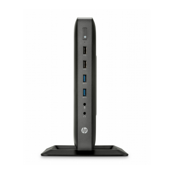
Product features Front panel components For more information, go to http://www.hp.com and search for your specific thin client model to find the model-specific QuickSpecs. Power button USB 3.0 ports (2) Flash drive activity LED Microphone port USB 2.0 ports (2) -
Page 10: Rear Panel Components
(14) Cable lock slot and rear cover latch *Available on some models. Refer to the model-specific QuickSpecs at www.hp.com for details. If the configurable port (item #10) is VGA, then the devices connected at boot up or subsequently disconnected determine which video ports are enabled and which is disabled. -
Page 11: Serial Number Location
Presence of an optional VGA or Fiber NIC port does not disable a DisplayPort port. Serial number location Every thin client includes a unique serial number located as shown in the following illustration. Have this number available when contacting HP customer service for assistance. Serial number location... -
Page 12: Hardware Changes
To reduce the risk of serious injury, read the Safety & Comfort Guide. It describes proper workstation, setup, posture, and health and work habits for computer users, and provides important electrical and mechanical safety information. The Safety & Comfort Guide is located on the HP website at http://www.hp.com/ergo. -
Page 13: Connecting The Power Cord
Connecting the power cord Plug the female end of the power cord into the power supply brick (1). Connect the other end of the power cord to an electrical outlet (2). Connect the round end of the power supply cord to the power supply connector on the rear of the computer (3). -
Page 14: Attaching The Stand
Attaching the stand CAUTION: The computer must be operated with the stand attached to ensure proper airflow around the computer. The computer can be used in either a tower or horizontal orientation with the stand included with the computer. Remove/disengage any security devices that prohibit opening the computer. Remove all removable media, such as USB flash drives, from the computer. - Page 15 NOTE: An optional Quick Release mounting bracket is available from HP for mounting the computer to a wall, desk, or swing arm. When the mounting bracket is used, do not install the computer with the I/O ports oriented towards the ground.
-
Page 16: Removing And Replacing The Access Panel
DO NOT use any access panel except the one that is provided by HP for use with this computer. Before removing the side access panel, be sure that the thin client is turned off and the power cord is disconnected from the electrical outlet. -
Page 17: Replacing The Access Panel
Move the access panel latch (1) to the left to release the access panel. Slide the access panel (2) approximately 6 cm (.24 in) toward the back of the chassis, and then lift the panel off of the computer. Replacing the access panel To replace the access panel: Set the access panel (1) onto the chassis approximately 6 cm (.24 in) inside the edge of the chassis, and then slide the panel toward the front of the chassis until it locks in place. - Page 18 Insert the hooks on the right side of the I/O panel (1) into the right side of the back of the chassis, and then press the left side (2) to the chassis until it locks in place. Chapter 2 Hardware changes...
-
Page 19: Installing Internal Usb Flash Drives
If the computer is an HP t620 PLUS Thin Client, push the fan assembly latch (1) toward the front of the computer and rotate the assembly (2) up and out of the way. - Page 20 Align the USB flash drive with the USB port and press the drive firmly into the port until it is securely seated. If the computer is an HP t620 PLUS Thin Client, rotate the fan assembly down, push the fan assembly latch (1) toward the front of the computer, lower the assembly (2) until it stops, and then release the latch.
-
Page 21: Installing Additional Memory
Replace and latch the access panel, and then reinstall the I/O panel. Replace the computer stand. Reconnect the power cord and turn on the computer. Lock any security devices that were disengaged when the computer cover or access panel was removed. -
Page 22: Populating Sodimm Sockets
Populating SODIMM sockets There are two SODIMM sockets on the system board with one total channel. The sockets are labeled DIMM1 and DIMM2. The system operates in single-channel mode at 1600 MHz. Item Description System Board Label Socket Color SODIMM1 socket, Channel A DIMM1 Black SODIMM2 socket, Channel A... -
Page 23: Installing Sodimms
Installing SODIMMs CAUTION: You must disconnect the power cord and wait approximately 30 seconds for the power to drain before adding or removing memory modules. Regardless of the power-on state, voltage is always supplied to the memory modules as long as the computer is plugged into an active AC outlet. Adding or removing memory modules while voltage is present may cause irreparable damage to the memory modules or system board. - Page 24 If the computer is an HP t620 PLUS Thin Client, push the fan assembly latch (1) toward the front of the computer and rotate the assembly (2) up and out of the way. Locate the memory compartment on the system board.
- Page 25 Remove the two screws and springs (1) securing the memory compartment cover. NOTE: Be sure to retain the two screws and the springs beneath them. Slide the memory compartment cover (2) slightly toward the front of the computer to free it, and then lift it out of the chassis.
- Page 26 Slide the new SODIMM (1) into the socket at approximately a 30° angle, and then press the SODIMM into the socket (2) so that the latches lock it in place. NOTE: A memory module can be installed in only one way. Match the notch on the module with the tab on the memory socket.
- Page 27 If the computer is an HP t620 PLUS Thin Client, rotate the fan assembly down, push the fan assembly latch (1) toward the front of the computer, lower the assembly (2) until it stops, and then release the latch. Replace and latch the access panel, and then reinstall the I/O panel.
-
Page 28: Installing A Pci-Express Card
Installing a PCI-Express card You may install an optional half-height PCI-Express (PCIe) card in the HP t620 PLUS Thin Client. A riser card is installed in this computer by default. WARNING! To reduce the risk of personal injury or equipment damage from electric shock, hot surfaces, or fire, disconnect the power cord from the power outlet and allow the internal system components to cool before you touch them. - Page 29 Locate the slot in the riser card. Slide the expansion slot cover left and remove it. Installing a PCI-Express card...
- Page 30 Align the PCIe card connectors with the slot in the riser card and the metal tab at the end of the card with the slot in the chassis. Press the PCIe card firmly into the slot in the riser card until it is securely seated and the tab is in the slot.
-
Page 31: Installing A Half-Height Pci-Express 2.0 Card
Installing a half-height PCI-Express 2.0 card You may install an optional half-height PCI-Express (PCIe) card in the HP t620 PLUS Thin Client. A riser card is installed in this computer by default. WARNING! To reduce the risk of personal injury or equipment damage from electric shock, hot surfaces, or fire, disconnect the power cord from the power outlet and allow the internal system components to cool before you touch them. - Page 32 Locate the slot in the riser card. Slide the expansion slot cover left and remove it. Chapter 2 Hardware changes...
- Page 33 Align the PCIe card connectors with the slot in the riser card and the metal tab at the end of the card with the slot in the chassis. Press the PCIe card firmly into the slot in the riser card until it is securely seated and the tab is in the slot.
-
Page 34: Security
Security The thin client is equipped with a hood sensor. You may also use a cable lock to secure the computer. For an additional layer of security, you may purchase a port cover to prevent unauthorized access to the rear ports. Hood sensor The hood sensor is a combination of hardware and software technology. -
Page 35: Cable Lock
These thin clients are designed to accept a security cable lock. This cable lock prevents unauthorized removal of the thin client, as well as locking devices installed inside the case. To order this option, visit the HP website at http://www.hp.com and search for your specific thin client model. -
Page 36: Removing And Replacing The Battery
Removing and replacing the access panel on page If the computer is an HP t620 PLUS Thin Client, perform the following steps: Push the fan assembly latch (1) toward the front of the computer and rotate the assembly (2) up and out of the way. - Page 37 Carefully press the new battery down to adhere the battery securely to the system board. If the computer is an HP t620 PLUS Thin Client, perform the following steps. If the cables from the PCIe riser card were disconnected in step 7 c, reconnect them.
- Page 38 Align the riser card with the socket on the system board and press the riser card firm into the socket. NOTE: The riser card can be installed in only one way. Match the notch on the card with the tab on the socket. If a PCIe card was installed, reinstall it.
- Page 39 Lock any security devices that were disengaged when the computer cover or access panel was removed. HP encourages customers to recycle used electronic hardware, HP original print cartridges, and rechargeable batteries. For more information about recycling programs, go to http://www.hp.com search for “recycle”.
-
Page 40: Appendix A Computer Setup (F10) Utility, Bios Settings
Computer Setup (F10) Utility, BIOS Settings Computer Setup (F10) Utilities Use Computer Setup (F10) Utility to do the following: Change factory default settings. Set the system date and time. Set, view, change, or verify the system configuration, including settings for processor, graphics, memory, audio, storage, communications, and input devices. -
Page 41: Using Computer Setup (F10) Utilities
Using Computer Setup (F10) Utilities Computer Setup can be accessed only by turning the computer on or restarting the system. To access the Computer Setup Utilities menu, complete the following steps: Turn on or restart the computer. Press either while the “Press the ESC key for Startup Menu” message is displayed at the bottom of the screen. -
Page 42: Computer Setup-File
Computer Setup—File NOTE: Support for specific Computer Setup options may vary depending on the hardware configuration. Option Description System Information Lists: Manufacturer Product name SKU number (some models) Serial number Asset Tag System Board ID Product Configuration ID System Board CT Number BIOS Revision BIOS Date Processor type... -
Page 43: Computer Setup-Storage
Computer Setup—Storage Option Description Device Lists all installed BIOS-controlled storage devices. When a device is selected, detailed information Configuration and options are displayed. The following options may be presented: Hard Disk: Size, model, firmware version, serial number. Storage Options SATA Emulation CAUTION: SATA emulation changes may prevent access to existing drive data and degrade or corrupt established volumes. -
Page 44: Computer Setup-Security
Computer Setup—Security NOTE: Support for specific Computer Setup options may vary depending on the hardware configuration. Table A-1 Computer Setup—Security Option Description Setup Password Allows you to set and enable a setup (administrator) password. NOTE: If the setup password is set, it is required to change Computer Setup options, flash the ROM, and make changes to certain plug and play settings under Windows. - Page 45 Clear Secure Boot Keys (Clear/Don’t Clear). Lets you clear the Secure Boot Key. Key ownership (HP keys/ Customer keys). Lets you change the keys of different owners. Fast Boot (Enable/Disable). Enable Fast Boot cause system boot by initializing a minimal set of devices which is required to launch active boot option.
-
Page 46: Computer Setup-Power
S4/S5 Wake on LAN (Disable/Enable). Permits the user to control whether the system should wake from S4 of S5 if a magic packet id received by NIC. Thermal CPU Fan speed (Read-Only), show the CPU fan speed in RPM on the t620 Flex system. Computer Setup—Advanced NOTE: Support for specific Computer Setup options may vary depending on the hardware configuration. - Page 47 Table A-3 Computer Setup—Advanced (for advanced users) (continued) Bus Options On some models, allows you to enable or disable: PCI SERR# Generation. Default is enabled. PCI VGA Palette Snooping, which sets the VGA palette snooping bit in PCI configuration space; only needed when more than one graphics controller is installed. Default is disabled. Device Options Allows you to set: Printer mode (Bi-Directional, EPP + ECP, Output Only).
-
Page 48: Changing Bios Settings From The Hp Bios Configure Utility (Hpbcu)
Changing BIOS Settings from the HP BIOS Configure Utility (HPBCU) Some BIOS settings may be changed locally within the operating system without having to go through the F10 utility . This table identifies the items that can be controlled with this method. - Page 49 Integrated Graphics Auto Disable, Force UMA Frame Buffer Size 512M 32M, 64M, 128M, 256M, 1G Multi-Processor Enable Disable Integrated Audio Enable Disable Internal Speaker Enable Disable NIC Option ROM Disable Download Changing BIOS Settings from the HP BIOS Configure Utility (HPBCU)
-
Page 50: Appendix B Diagnostics And Troubleshooting
Diagnostics and Troubleshooting LEDs Table B-1 Power and IDE Flash Activity LEDs Status Power LED Off When the unit is plugged into the wall socket and the Power LED is off, the unit is powered off. However, the network can trigger a Wake On LAN event in order to perform management functions. -
Page 51: Wake-On Lan
Wake-on LAN Wake-on LAN (WOL) allows a computer to be turned on or resumed from sleep or hibernation state by a network message. You can enable or disable WOL in Computer Setup using the S5 Maximum Power Savings setting. To enable or disable WOL: Turn on or restart the computer. -
Page 52: Resetting The Setup And Power-On Passwords
Resetting the Setup and power-on Passwords You can reset the Setup and Power-on passwords as follows: Turn off the computer and disconnect the power cord from the power outlet. Remove the side access panel and the metal side cover. Remove the password jumper from the system board header labeled PSWD/E49. Replace the metal side cover and the side access panel. -
Page 53: Interpreting Post Diagnostic Front Panel Leds And Audible Codes
Interpreting POST Diagnostic Front Panel LEDs and Audible Codes This section covers the front panel LED codes as well as the audible codes that may occur before or during POST that do not necessarily have an error code or text message associated with them. WARNING! When the computer is plugged into an AC power source, voltage is always applied to the system board. - Page 54 LEDs continue until Reseat memory modules. problem is solved. Replace memory modules one at a time to isolate the faulty module. Replace third-party memory with HP memory. Replace the system board. Red Power LED flashes six Pre-video graphics error.
- Page 55 Table B-3 Diagnostic Front Panel LEDs and Audible Codes (continued) Activity Beeps Possible Cause Recommended Action Red Power LED flashes eight Invalid ROM based on Reflash the system ROM with the latest BIOS times, once every second, bad checksum. image using the BIOS Recovery procedure. followed by a two second Replace the system board.
-
Page 56: Post Numeric Codes And Text Messages
POST Numeric Codes and Text Messages This section covers those POST errors that have numeric codes associated with them. The section also includes some text messages that may be encountered during POST. NOTE: The computer will beep once after a POST text message is displayed on the screen. Table B-4 Numeric Codes and Text Messages Control panel message... - Page 57 Run the Drive Protection will fix an erroneous error message.) System test using F2 Diagnostics. Apply hard drive firmware patch if applicable. (Available at http://www.hp.com/support.) Back up contents and replace hard drive. Invalid Electronic Serial Number Electronic serial number is missing.
-
Page 58: Troubleshooting
Table B-4 Numeric Codes and Text Messages (continued) Control panel message Description Recommended action Network Server Mode Active and No Keyboard failure while Network Server Reconnect keyboard with computer Keyboard Attached Mode enabled. turned off. Check connector for bent or missing pins. - Page 59 Table B-5 Power-On Troubleshooting (continued) No link or activity on the network RJ-45 Verify that the network is not down. LEDs or the LEDs do not illuminate blinking Make sure the RJ-45 cable is good by installing the RJ-45 cable onto a green after powering on the thin client unit.
-
Page 60: Diskless (No-Flash) Unit Troubleshooting
Diskless (No-Flash) Unit Troubleshooting This section is only for those units that do not have ATA Flash capability. Because there is no ATA Flash in this model the boot priority sequence is: USB device When the unit boots, the monitor should display the following information: Table B-6 Diskless Unit Troubleshooting Item... -
Page 61: Configuring A Pxe Server
NOTE: All PXE software is supported by authorized service providers on a warranty or service contract basis. Customers that call the HP Customer Service Center with PXE issues and questions should be referred to their PXE provider for assistance. Additionally, refer to the following: –... -
Page 62: Appendix C Restoring The Flash Image
Download and run the Package-for-the-Web deliverable (an .exe file) that contains the original factory image for the thin client. The HP Thin Client Imaging Tool (CRStart.exe) runs automatically. Choose one of the deployment options: Each option is described in the following paragraphs. -
Page 63: Formatting A Usb Flash Drive
first restart of the thin client following the restore process, it may take approximately 15 minutes to unbundle the software before the Windows Desktop is displayed. Formatting a USB Flash Drive CAUTION: To prevent loss of data, be sure that you have saved any user-created data from the USB drive to another drive. -
Page 64: Deploying With Pxe
Deploying with PXE Ensure that IBRPE.EXE and FLASH.IBR file exist. Add the following command to execute IBRPE in WinPE environment: [full path] \IBRPE.EXE [full path]\FLASH.IBR HD0 To view the IBR command line options: At the command prompt, type IBR.EXE /? and press Enter. See your documentation if using a different PXE server, such as Altiris Deployment Solution. -
Page 65: Appendix D Device Management
Discover, Asset Management, Deployment and Configuration. For more information on HP Device Manager, please visit www.hp.com/go/hpdm. If you wish to manage the t620 with other management tools such as Microsoft SCCM or LANDesk, go www.hp.com/go/clientmanagement for more information. -
Page 66: Appendix E Adding An Image Restore Tool
Adding an Image Restore Tool Ensure that the boot order is set to use the Network as the first boot device. Ensure that IBR.exe (Image Restore) and Flash.dd are stored in the same directory on the server. (e.g., c:\program files\altiris\express\deployment server\images) From the Altiris Deployment Server Console, click File >... -
Page 67: Appendix F System Bios
Updating or restoring a BIOS HP Device Manager HP Device Manager can be used to update the BIOS of a thin client. Customers can use a pre-built BIOS add-on or can use the standard BIOS upgrade package along with an HP Device Manager File and Registry template. - Page 68 As a general rule, updating the BIOS will modify measurement values stored in the Platform Configuration Registers (PCRs) of the system's security module. Temporarily disable technologies that use these PCR values to ascertain platform health (BDE is one such example) prior to flashing the BIOS. Once you update the BIOS, re-enable the functions and restart the system so that you can take new measurements.
-
Page 69: Appendix G Power Cord Set Requirements
Power cord set requirements The power supplies on some computers have external power switches. The voltage select switch feature on the computer permits it to operate from any line voltage between 100-120 or 220-240 volts AC. Power supplies on those computers that do not have external power switches are equipped with internal switches that sense the incoming voltage and automatically switch to the proper voltage. -
Page 70: Country-Specific Requirements
Country-specific requirements Additional requirements specific to a country are shown in parentheses and explained below. Country Accrediting Agency Country Accrediting Agency Australia (1) EANSW Italy (1) Austria (1) Japan (3) METI Belgium (1) CEBC Norway (1) NEMKO Canada (2) Sweden (1) SEMKO Denmark (1) DEMKO... -
Page 71: Appendix H Statement Of Volatility
Follow the instructions to flash the BIOS that are found on the website. Flashing the BIOS will reset it back to factory settings. Turn on the system, and while system is powering on, and after the HP splash screen, press the key to enter BIOS setup screen. - Page 72 TCG Firmware The information contained herein is subject to change without notice. The only warranties for HP products and services are set forth in the express warranty statements accompanying such products and services. Nothing herein should be construed as constituting an additional warranty.
-
Page 73: Appendix I Specifications
** The operating temperature range when the thin 1°C/300 m (1.8°F/1000 ft) to a maximum of 3 Km client is attached to a flat panel using the HP Quick (10,000 ft), with no direct, sustained sunlight. Upper limit Release is 10°C to 35°C (50°F to 95°F). - Page 74 (max. allowed rate of change is 457m per minute or 1500 ft per minute) Power Supply HP t620 Thin Client HP t620 PLUS Thin Client Operating Voltage Range 100 VAC to 240 VAC 100 VAC to 240 VAC Rated Line Frequency...
- Page 75 Index disabling/enabling Wake-on LAN access panel (WOL) 43 memory removing 8 diskless troubleshooting 52 installation 13 replacing 9 DVI connector locations 2 socket population 14 adding an image restore tool 58 specifications 13 altitude specifications 66 microphone connector location 1 error audible codes 45 codes 45...
- Page 76 removing warnings access panel 8 burn 4, 11, 15, 20, 23 battery 28 electric shock 4, 8, 20, 23, replacing access panel 9 grounding plug 4 battery 28 NIC receptacles 4 resetting the Administrator password 44 restore 58 restoring the flash image 54 RJ-45 connector location 2 secure cable routing slot 2 security 26...
Need help?
Do you have a question about the t620 and is the answer not in the manual?
Questions and answers