Table of Contents
Advertisement
Available languages
Available languages
Quick Links
Advertisement
Table of Contents

Subscribe to Our Youtube Channel
Related Manuals for DFI 855GME-MGF


Summary of Contents for DFI 855GME-MGF
- Page 1 855GME-MGF System Board User’s Manual Carte Mère Manuel Pour Utilisateur System-Platine Benutzerhandbuch Manual del Usuario de Placas Base Ðóêîâîäñòâî Ïîëüçîâàòåëÿ Ðóêîâîäñòâî Ïîëüçîâàòåëÿ Ðóêîâîäñòâî Ïîëüçîâàòåëÿ Ðóêîâîäñòâî Ïîëüçîâàòåëÿ Ðóêîâîäñòâî Ïîëüçîâàòåëÿ 935-855GM1-100 84020501...
- Page 2 Quick Setup Guide Copyright This publication contains information that is protected by copyright. No part of it may be reproduced in any form or by any means or used to make any transformation/adaptation without the prior written permission from the copyright holders.
-
Page 3: Table Of Contents
Quick Setup Guide Table of Contents Chapter 1 Quick Setup Guide..........Chapter 2 English..............Chapter 3 Français..............Chapter 4 Deutsch................Chapter 5 Español................Chapter 6 Ðóññêèé............... The user’s manual in the provided CD contains detailed information about the system board. If, in some cases, some information doesn’t match those shown in this manual, this manual should always be re- garded as the most updated version. -
Page 4: Chapter 1 Quick Setup Guide
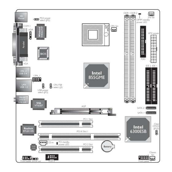
Quick Setup Guide Chapter 1 - Quick Setup Guide 1.1 System Board Layout DDR 1 DDR 2 2nd fan PS/2 power Mouse DIMM standby select (JP2) power LED COM 1 CPU fan IrDA ATX power BIOS IDE 2 IDE 1 1394_2 Intel USB 3-4... -
Page 5: Clear Cmos Data
Quick Setup Guide 1.2 Jumpers 1.2.1 Clear CMOS Data JP10 1-2 On: Normal 2-3 On: (default) Clear CMOS Data 1.2.2 PS/2 Power Select 1-2 On: 5V 2-3 On: 5VSB (default) Important: The 5VSB power source of your power supply must support ≥... - Page 6 Quick Setup Guide 1.2.3 USB Power Select 1-2 On: 5V 2-3 On: 5VSB (default) Important: If you are using the Wake-On-USB Keyboard/Mouse function for 2 USB ports, the 5VSB power source of your power supply must support ≥ 1.5A. If you are using the Wake-On-USB Keyboard/Mouse function for 3 or more USB ports, the 5VSB power source of your power supply must support ≥...
- Page 7 Quick Setup Guide 1.2.4 CPU FSB Select 1-2 On: 2-3 On: All Off: 400MHz Reserved 533MHz (Default) Important: • If you are using a CPU whose frequency has been locked by the manufacturer, overclocking will have no effect. • Overclocking may result to the CPU’s or system’s instability and are not guaranteed to provide better system performance.
-
Page 8: I/O Connectors
Quick Setup Guide 1.3 Rear Panel I/O Ports PS/2 Mouse Parallel 1394_2 Mic-in Line-in Line-out PS/2 KB COM 1 USB 3-4 USB 1-2 1.4 I/O Connectors 1.4.1 Audio (Rear Audio and Front Audio) Mic-in Line-in Rear audio Line-out Front audio 2-channel 6-channel 4-channel... - Page 9 Quick Setup Guide 1.4.2 IEEE 1394 1394_2 1394_1 1 2 1.4.3 Serial Ports COM 1 COM 2 1...
- Page 10 Quick Setup Guide 1.4.4 CD-in Internal Audio Connector Ground Ground Left audio Right audio channel channel 1.4.5 S/PDIF-out Connector SPDIF out...
-
Page 11: Quick Setup Guide
Quick Setup Guide 1.4.6 Floppy Disk Drive Connector 1.4.7 Serial ATA Connectors SATA 2 SATA 1 Note: The Intel 6300ESB south bridge chip allows configuring RAID on Serial ATA drives. It supports RAID 0 and RAID 1. -
Page 12: Ide Disk Drive Connectors
Quick Setup Guide 1.4.8 IDE Disk Drive Connectors IDE 2 IDE 1 1.4.9 IrDA Connector IRTX Ground IRRX N. C. Note: The sequence of the pin functions on some IR cable may be reversed from the pin function defined on the system board. Make sure to connect the cable connector to the IR connector according to their pin functions. -
Page 13: Cooling Fan Connectors
Quick Setup Guide 1.4.10 Cooling Fan Connectors Power Ground Sense Power Ground Sense 2nd fan CPU fan Power Ground Sense Chassis fan 1.4.11 Power Connector +12V 5VSB PW-OK Ground Ground Ground Ground Ground PS-ON Ground Ground -12V 3.3V 3.3V 3.3V Important: To ensure that adequate power is provided, use a 250 Watt (or greater) power supply. - Page 14 Quick Setup Guide 1.4.12 DIMM and PCI Standby Power LEDs DIMM Standby Power LED PCI Standby Power LED Important: If the DIMM Standby Power LED or PCI Standby Power LED is lighted, you must power-off the system then turn off the power supply’s switch or unplug the power cord prior to installing any memory modules or add-in cards.
-
Page 15: Front Panel Connectors
Quick Setup Guide 1.4.13 Front Panel Connectors RESET SW HDD-LED PWR-LED PWR-BTN Pin Assignment Pin Assignment N. C. N. C. LED Power PWR-LED LED Power Signal HDD-LED HDD Power PWR-BTN Power PWR-BTN Signal Signal RESET SW Ground RST Signal N. C. N. -
Page 16: Chapter 2 English
English Chapter 2 - English 2.1 Features and Specifications Processor ® ® ® • Intel Pentium M / Celeron M processor 400MHz system bus Supports 64-bit host data bus and 32-bit addressing • Processor socket: mPGA479M Chipset ® • Intel 855GME chipset ®... - Page 17 English RTC timer to power-on the system • AC power failure recovery Hardware Monitor • Monitors CPU/system temperature and overheat alarm • Monitors 5VSB(V)/VBAT(V)/1.5V/3.3V/5V/12V/CPU(V) voltages and failure alarm • Monitors CPU/chassis/2nd fan speed and failure alarm • Read back capability that displays temperature, voltage and fan speed Onboard Graphics Features •...
-
Page 18: Sata
English Onboard LAN Features • RTL8110S Gigabit ethernet controller • Supports 10Mbps, 100Mbps and 1Gbps data transmission • IEEE 802.3 (10/100Mbps) and IEEE 802.3ab (1Gbps) compliant Serial ATA Interface with RAID • Supports two SATA (Serial ATA) interfaces which are compliant with SATA 1.0 specification (1.5Gbps interface) •... -
Page 19: Raid Configuration
English • 2 40-pin IDE connectors • 1 floppy connector • 1 ATX power supply connector • 1 front panel connector • 3 fan connectors Expansion Slots • 1 AGP 4x slot • 1 PCI-X slot • 2 PCI slots Compatibility •... - Page 20 English Installing the RAID Driver While Installing Windows ® XP or ® Windows 2000 The steps below will instruct you on installing the 6300ESB RAID ® ® driver while in the process of installing Windows XP or Windows 2000 on a RAID 0 or RAID 1 Volume Serial ATA drives. 1.
-
Page 21: Package Checklist
English 2.3 Package Checklist The system board package contains the following items: The system board A user’s manual One IDE cable One floppy cable Two Serial ATA data cables One Serial ATA power cable One “Main Board Utility” CD One Intel RAID driver diskette One I/O shield One CPU fan and heat sink assembly If any of these items are missing or damaged, please contact your... -
Page 22: Chapter 3 Français
Français Chapter 3 - Français 3.1 Caractéristiques et Spécifications Processeur ® ® ® • Les processeurs Intel Pentium M / Celeron Interface du bus système 400MHz Supporte 64-bit hôte donnée bus et adressage de 32 bits • Socket mPGA479M Chipset •... - Page 23 Français • Gère la vitesse de ventilateur du ventilateur de CPU/chassis/2nd • Affichage température, voltage et éventez la vitesse Fonctions de la Graphique Intégrée • Jusqu’à 64MB Mémoire Dynamique • Dynamische videospeicherallozierung à 133/200/250MHz • Rendez la fréquence de noyau à 100/133/166/200/250MHz ®...
- Page 24 Français Le Panneau des Ports Entrée/Sortie en Arrière • 1 port souris PS/2 • 1 port clavier PS/2 • 1 port parallèle DB-25 • 1 port de DB-9 série • 1 port de DB-15 VGA • 1 port IEEE 1394 •...
- Page 25 Français 3.2 Configuration du RAID Les instructions suivantes décrivent les étapes essentielles de la configuration du RAID. 1. Activez le champ “On-Chip Serial ATA” en sélectionnant “Enhanced Mode”. (Sous-menu “Integrated Peripherals” dans la section “OnChip IDE Device” du Award BIOS.) 2.
- Page 26 Français 3.3 Liste de Vérification de l’Emballage L’emballage de la carte système contient les éléments suivants: 1 carte système 1 manuel utilisateur 1 câble IDE 1 câble FDD 2 câble SATA 1 câble d’alimentation SATA 1 CD “Mainboard Utility” 1 disquette Intel RAID 1 plaque I/O 1 ensemble de ventilateur et de radiateur Si l’un de ces éléments n’était pas dans l’emballage ou s’il était...
-
Page 27: Chapter 4 Deutsch
Deutsch Chapter 4 - Deutsch 4.1 Leistungsmerkmale und Technische Daten Prozessor ® ® ® • Intel Pentium M / Celeron M Prozessor Interface des Systemreifens 400MHz Supports 64-bit Wirt Datenübertragungsweg und 32-bit Wenden • Prozessor socket: mPGA479M Chipset • Intel 855GME chipset ®... - Page 28 Deutsch System Health Monitor Funktions • Überwachung der Temperatur des CPU/Systems sowie Warnsignal bei Überhitzung • Überwachung der Spannungen des 5VSB(V)/VBAT(V)/1.5V/3.3V/ 5V/12V/CPU(V) • Überwachung der Geschwindigkeit des CPU/Chassis/2nd Ventilators • Anzeige Temperatur, Spannung und lockern Sie Geschwindigkeit Bordgraphikmerkmäle • Bis zu 64MB dynamische videospeicherallozierung •...
- Page 29 Deutsch IEEE 1394 Schnittstelle • VIA VT6307 • Uunterstützt 2 Ports 100/200/400 Mbps AGP (Accelerated Graphics Port) • Unterstützt 1.5V AGP 4x (1066MB/sek.) Erweiterungskarten. 3.3V AGP Karten werden nicht unterstützt. • Unterstützt AGP 2.0 Spezifikationen Ein-/Ausgabe-Porte an der Rückwand • 1 Mini-DIN-6-Anschluß für eine PS/2-Maus •...
- Page 30 Deutsch Die Druckplatte • microATX • 24.4cm (9.61") x 23cm (9.06") 4.2 RAID-Konfiguration Das folgende beschreibt die Schritte auf zusammenbauenüberfall. 1. Stellen Sie das Feld “On-Chip Serial ATA” auf “Enhanced Mode”. (Submenu Integrated Peripherals - “OnChip IDE Device” Teil Award BIOS.) 2.
- Page 31 Deutsch 4.3 Verpackungsliste In der Verpackung der Systemplatine sind folgende Artikel enthalten: 1 Systemplatine 1 Benutzerhandbuch 1 IDE-Kabel 1 FDD-Kabel 2 SATA-Kabel 1 SATA-Energiekabel-Kabel 1 CD mit “Mainboard Utility” 1 Diskette Intel RAID driver 1 I/O-Shutzdeckel 1 Ventilator und Kühlblech Fehlt einer dieser Ar tikel oder weist einer dieser Ar tikel Beschädigungen auf, wenden Sie sich an Ihren Händler oder Vertreter.
-
Page 32: Chapter 5 Español
Español Chapter 5 - Español 5.1 Características y Especificaciones Procesador ® ® ® • Procesador Intel Pentium M / Celeron Interface de la barra sistémica 400MHz Soporta ómnibus de datos 64-bit de anfitrión y dirección 32-bit • Zócalo: mPGA479M Chipset ®... - Page 33 Español • Vigila la velocidad del abanico del abanido del CPU/chassis/2nd • Demostración temperaturas, voltajes y aviente la velocidad Características de Gráficos Interno • Hasta 64MB of asignación de memoria video dinámica • Frecuencia de la base de la exhibición en 133/200/250MHz •...
- Page 34 Español Panel de reverso de conectores de entrada - Salida • 1 puerto de ratón PS/2 mini-DIN-6 • 1 puerto de teclado mini-DIN-6 PS/2 • 1 puerto paralelo de DB-25 • 1 puerto de serie DB-9 • 1 puerto de VGA DB-15 •...
- Page 35 Español 5.2 Configuración RAID A continuación le mostramos los pasos básicos que ha de seguir para llevar a cabo la configuración RAID. 1. Establezca el valor de la opción “On-Chip Serial ATA” como “Enhanced Mode”. (submenú Integrated Peripherals – sección “OnChip IDE Device”...
- Page 36 Español completar la instalación. 5.3 Lista de Chequeo del Paquete El paquete del tablero de sistema contiene los siguientes artículos: 1 tablero de sistema 1 manual de usuario 1 cable de IDE 1 cable de FDD 2 cable SATA 1 cable de alimentacion SATA 1 CD de “Mainboard Utility”...
-
Page 37: Chapter 6 Ðóññêèé
Ðóññêèé Ãëàâà Ãëàâà Ãëàâà 6 6 6 6 6 - - - - - Ðóññêèé ÿçûê Ðóññêèé ÿçûê Ðóññêèé ÿçûê Ãëàâà Ãëàâà Ðóññêèé ÿçûê Ðóññêèé ÿçûê 6.1 Õàðàêòåðèñòèêè è ñâîéñòâà 6.1 Õàðàêòåðèñòèêè è ñâîéñòâà 6.1 Õàðàêòåðèñòèêè è ñâîéñòâà 6.1 Õàðàêòåðèñòèêè è ñâîéñòâà 6.1 Õàðàêòåðèñòèêè... - Page 38 Ðóññêèé • Mîíèòîðèíã íàïðÿæåíèé 5VSB(V)/VBAT(V)/1.5V/3.3V/ 5V/12V/CPU(V) • Mîíèòîðèíã ñêîðîñòè âðàùåíèÿ âåíòèëÿòîðà CPU/ chassis/2nd Ãðàôèêà Ãðàôèêà Ãðàôèêà Ãðàôèêà Ãðàôèêà • Äî 64ÌÁ äèíàìè÷åñêîé âèäåî ïàìÿòè • ×àñòîòà ÿäðà 133/200/250MÃö • ×àñòîòà ðåíäåðèíãà 100/133/166/200/250Ãö • Intel® Dual-Frequency Graphics Technology • 2D äâèæîê, 3D äâèæîê •...
- Page 39 Ðóññêèé • Ïîääåðæèâàåò ñïåöèôèêàöèè AGP 2.0 Ïîðòû Ââîäà/Âûâîäà (I/O) çàäíåé ïàíåëè Ïîðòû Ââîäà/Âûâîäà (I/O) çàäíåé ïàíåëè Ïîðòû Ââîäà/Âûâîäà (I/O) çàäíåé ïàíåëè Ïîðòû Ââîäà/Âûâîäà (I/O) çàäíåé ïàíåëè Ïîðòû Ââîäà/Âûâîäà (I/O) çàäíåé ïàíåëè • 1 ìèíè-DIN-6 PS/2 ïîðò äëÿ ìûøè • 1 ìèíè-DIN-6 PS/2 ïîðò äëÿ êëàâèàòóðû •...
- Page 40 Ðóññêèé 2. Óñòàíîâèòå ïîëå “SATA Mode” íà “RAID”. (ïîäìåíþ Integrated Peripherals - “OnChip IDE Device” ðàçäåë Award BIOS.) 3. Ïåðåçàãðóçèòå êîìïüþòåð. 4. Çàïóñòèòå óòèëèòó Intel RAID BIOS, íàæàâ êíîïêó <Ctrl> è <I> ïîñëå âêëþ÷åíèÿ êîìïüþòåðà. Óòèëèòà íóæíà äëÿ íàñòðîéêè è óïðàâëåíèÿ äèñêàìè RAID èíòåðôåéñîâ Serial ATA.
Need help?
Do you have a question about the 855GME-MGF and is the answer not in the manual?
Questions and answers