Advertisement
Table of Contents
- 1 Table of Contents
- 2 Preinstallation Instructions for Dealers
- 3 Bypass Valve
- 4 Installation
- 5 Installation
- 6 Programming Procedures
- 7 Operating Displays and Instructions
- 8 Start-Up Instructions
- 9 Troubleshooting Guide
- 10 Replacement Parts
- 11 Installation Fitting Assemblies
- 12 Specifications
- 13 Quick Reference Guide
- Download this manual
Advertisement
Table of Contents

Summary of Contents for DuPure Impression Plus Series
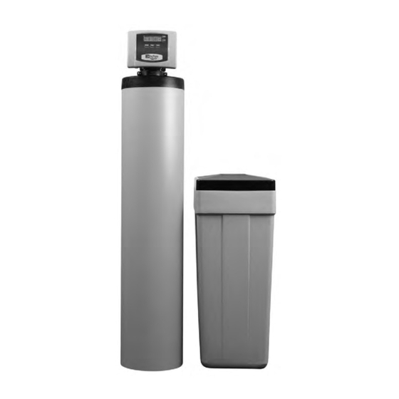
- Page 1 Installation Instructions & Owner’s Manual Impression Plus Series ® Metered Water Softeners...
-
Page 2: Table Of Contents
Your Impression Plus Series water conditioners are precision built, high quality products. These units will deliver conditioned water for many years to come, when installed and operated properly. Please study this manual carefully and understand the cautions and notes before installing. -
Page 3: Preinstallation Instructions For Dealers
PREINSTALLATION INSTRUCTIONS FOR DEALERS: The manufacturer has preset the water treatment unit’s sequence of cycles, cycle times, salt dose, exchange capacity and salt dose refill time. The dealer should read this page and guide the installer regarding hardness, day override, and time of regeneration, before installation. - Page 4 1. NORMAL OPERATION POSITION: The inlet and outlet handles point in the direction of flow indicated by the engraved arrows on the control valve. Water flows through the control valve for normal operation of a water softener. During the regeneration cycle this position provides regeneration water to the unit, while also providing untreated water to the distribution system (Fig.
-
Page 5: Installation
INSTALLATION: GENERAL INSTALLATION & SERVICE WARNINGS The control valve, fittings and/or bypass are designed to accommodate minor plumbing misalignments. There is a small amount of “give” to properly connect the piping, but the water softener is not designed to support the weight of the plumbing. Do not use Vaseline, oils, other hydrocarbon lubricants or spray silicone anywhere. -
Page 6: Installation
6. INLET/OUTLET PLUMBING: Be sure to install Bypass Valve onto main control valve before beginning plumbing. Make provisions to bypass outside hydrant and cold hard water lines at this time. Install an inlet shutoff valve and plumb to the unit’s bypass valve inlet located at the right rear as you face the unit. -
Page 7: Programming Procedures
PROGRAMMING PROCEDURES: 1. Set time of day: Time of day should only need to be set after extended power outages or when daylight saving time begins or ends. If an extended power outage occurs, the time of day will flash on and off indicating that the time should be reset. -
Page 8: Operating Displays And Instructions
2. Programming cont’d: STEP 4 – REGENERATION HOUR: The manufacturer has factory set 2:00 A.M. as the default. This is the hour of day for regeneration and can be reset by using + or — buttons. “AM/PM” toggles after 12. The default time is 2:00 a.m. (recommended for a normal household). Press to go to step 5. - Page 9 3. MANUAL REGENERATION: Sometimes there is a need to regenerate before the control valve calls for it. This may be needed if a period of heavy water use is anticipated or when the system has been operated without salt. • To initiate a manual regeneration at the next preset regeneration time, press and release MANUAL REGENERATION .
- Page 10 ERROR 5. ERROR MESSAGE: If the word “ERROR” and a number are alternately flashing on the display record the number and contact the dealer for help. This indicates that the control valve was not able to function properly. 6. BRINE TANK MAINTENANCE AND SALT: Refill the brine tank as necessary, making sure at least 1/3 of the brine tank is full at all times.
-
Page 11: Start-Up Instructions
START-UP INSTRUCTIONS: • After installation is complete, rotate bypass handles to bypass mode (see Fig.2 on page 4). • Turn on water and check for leaks. • Fully open a cold water faucet — preferably a laundry sink or bathtub without an aerator. •... -
Page 12: Troubleshooting Guide
TROUBLESHOOTING GUIDE: PROBLEM CAUSE CORRECTION A. transformer unplugged A. reconnect transformer Timer does B. no power at outlet B. repair or use working outlet not display C. defective transformer C. replace transformer time of day D. defective PC board D. replace PC board A. - Page 13 PROBLEM CAUSE CORRECTION A. transformer unplugged A. connect transformer and PC board power Valve does not regenerate B. no power at outlet B. restore power automatically C. broken drive gear or drive cap assembly C. replace gear or drive cap assembly when REGEN button is pressed...
-
Page 14: Replacement Parts
REPLACEMENT PARTS: FRONT COVER AND DRIVE ASSEMBLY Item No. Part No. Description Qty. CV3540P-DUPURE DuPure Impression Plus ® cover CV3107-1 Motor CV3106-1 Drive bracket & spring clip CV3579WI PC board, CC CV3110 Drive gear, 12 x 36 CV3109 Drive gear cover... - Page 15 REPLACEMENT PARTS: PISTON ASSEMBLY Item No. Part No. Description Qty. CV3005 1" spacer stack assembly CV3430 1.25" spacer stack assembly CV3004 Drive cap assembly CV3135 O-ring 228 CV3011 1" piston assembly downflow NOTE: For Impression Plus CV3011-01 1" piston assembly upflow ®...
- Page 16 REPLACEMENT PARTS: BYPASS VALVE Item No. Part No. Description Qty. CV3151 Nut, 1" quick connect CV3150 Split ring CV3105 O-ring 215 CV3145 Bypass rotor, 1" CV3146 Bypass cap CV3147 Bypass handle CV3148 Bypass rotor seal retainer CV3152 O-ring 135 CV3155 O-ring 112 CV3156 O-ring 214...
- Page 17 REPLACEMENT PARTS: INJECTOR ASSEMBLIES Item No. Part No. Description Qty. CV3176 Injector cap CV3152 O-ring 135 CV3177-01 Injector screen CV3010-1Z Injector assembly plug CV3010-1A A injector assembly, BLACK CV3010-1B B injector assembly, BROWN CV3010-1C C injector assembly, VIOLET D injector assembly, CV3010-1D CV3010-1E E injector assembly,...
- Page 18 REPLACEMENT PARTS: DRAIN LINE ASSEMBLY 3/4" Item No. Part No. Description Qty. CH4615 Elbow locking clip CPKP10TS8-BULK Optional insert, 5/8" tube CV3192 Optional nut, 3/4" drain elbow CV3158-01 Drain elbow, 3/4" NPT with O-ring CV3163 O-ring 019 CV3159-01 DLFC retainer assembly CV3162-007 0.7 DLFC for 3/4"...
- Page 19 REPLACEMENT PARTS: WATER METER & METER PLUG Item No. Part No. Description Qty. CV3151 Nut, 1" QC CV3003 Meter assembly, includes items 3 & 4 CV3118-01 Turbine assembly CV3105 O-ring 215 CV3003-01 Meter plug assembly CV3013 Optional mixing valve SERVICE WRENCH - CV3193-01 Although no tools are necessary to assemble or disassemble the valve, the Service Wrench, (shown in various positions on the valve) is...
- Page 20 BRINE TANK ASSEMBLY Item No. Part No. Description Qty. CG2195-14 15" x 17" DuPure brine tank cover CG2189 Round brine tank cover, black CG21517RB1CDL 15" x 17" platinum brine tank CG21840CB1C00 18" x 40" round brine tank, black CH1030-27 4" x 27" brine well (18 x 33 BT) CH1030-34.5...
- Page 21 REPLACEMENT PARTS: CABINET BRINE TANK ASSEMBLY Item No. Part No. Description Qty. CG 2197-01 Salt and tank cover (must be ordered together CG2724HP-01 Windsor cabinet, white with black lids CH1090-01 Optional salt grid for 8" diameter tank and 4" brine well CH1090-02 Optional salt grid for 9"...
-
Page 22: Installation Fitting Assemblies
INSTALLATION FITTING ASSEMBLIES: 1" PVC MALE NPT ELBOW 3/4" & 1" PVC SOLVENT ELBOW Item Item Part No. Description Qty. Part No. Description Qty. CV3007 1" PVC male NPT elbow assembly CV3007- 01 3/4" & 1" PVC solvent elbow assembly CV3151 Nut, 1"... -
Page 23: Specifications
1-1/4" & 1-1/2" BRASS SWEAT 1-1/4" & 1-1/2" PVC SOLVENT Item Item Part No. Description Qty. Part No. Description Qty. CV3007- 09 1-1/4 & 1-1/2" brass sweat assembly CV3007- 07 1-1/4" & 1-1/2" PVC solvent assembly CV3151 Nut, 1" quick connect CV3151 Nut, 1"... -
Page 24: Quick Reference Guide
+ and — buttons 9. Press NEXT complete and return to normal operation. 11321 Windfern Road • Houston, TX 77064 Phone: 281-890-7900 • Toll-free: 1-877-534-5837 ©2008 DuPure International All rights reserved. LIT-DP IMP Man ROPU 4/08 250...
Need help?
Do you have a question about the Impression Plus Series and is the answer not in the manual?
Questions and answers
Been using crystal s but accidentally bought rocks, can I use that in impression systems.