
Related Manuals for Avdel 7271


Summary of Contents for Avdel 7271
- Page 1 I n s t r u c t i o n M a n u a l Pass onto user to read and keep for reference P n e u m a t i c P o w e r T o o l 0727 type 07271 - 07274...
- Page 2 AVDEL policy is one of continuous development. Specifications shown in this document may be subject to changes which may be introduced after publication. For the latest information always consult Avdel. S P E C I F I C A T I O N S F O R 0 7 2 7 T Y P E T O O L ■...
-
Page 3: Table Of Contents
O N T E N T S S A F E T Y General Specific to 0727 Tool I N T E N T O F U S E Tool Capability Tool Dimensions P U T T I N G I N T O S E R V I C E Air Supply Bush Stops Cursor... - Page 4 RECOMMENDED AND SUPPLIED BY AVDEL. ANY MODIFICATION UNDERTAKEN BY THE CUSTOMER TO THE TOOL/MACHINE, NOSE ASSEMBLIES, ACCESSORIES OR ANY EQUIPMENT SUPPLIED BY AVDEL OR THEIR REPRESENTATIVES, SHALL BE THE CUSTOMER'S ENTIRE RESPONSIBILITY. AVDEL WILL BE PLEASED TO ADVISE UPON ANY PROPOSED MODIFICATION.
-
Page 5: General
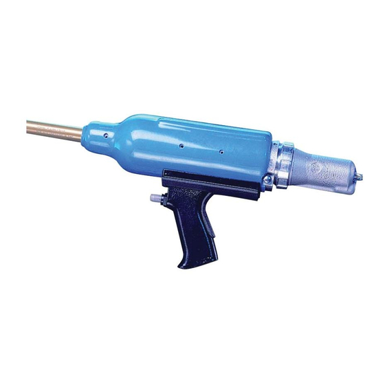
ARE SHARP EDGES OR CORNERS ON THE APPLICATION. THE OPERATING PRESSURE SHALL NOT EXCEED 8 BAR - 120 LBF/IN BENCH MOUNTED TOOLS MUST NOT BE USED WITHOUT AN AVDEL GUARD AND WITH THE SHIELD IN POSITION ABOVE THE TOOL BARREL AND THEY SHOULD NOT BE OPERATED IF THE GUARD IS DAMAGED IN ANY WAY. - Page 6 There are two models: the 07271 and 07274 are hand-held and can be suspended vertically through a ring at the rear of the tool. Both models will place most repetition fasteners, as shown on the tables below.
-
Page 7: Tool Capability
07271 AND 07274 MODELS These are hand held models which can be suspended vertically from a ring mounted at the rear of the tool. While the 07274 is less powerful with only two pistons, (see differences on the general assembly, page 25), it gives greater access with its longer barrel protusion. -
Page 8: Air Supply
To ensure maximum tool life and minimum tool maintenance, these should be fitted within 3 metres of the air inlet point on the tool itself for the 07271 and 07274 models, see diagram below. -
Page 9: Bush Stops
B U S H S T O P S I M P O R T A N T Bush stops are fitted to reduce the stroke length of the tool thus the tool cycle time and shock loads. Minimising shock loads will increase the efficiency of the tool and will prolong the life of the mandrel. -
Page 10: Loading The Tool
To reverse the orientation of the cursor, follow these steps: Item numbers in bold refer to the general assembly and parts list CURSOR on pages 25 and 26. SPRING LOADED END ■ Remove tail jaw assembly 1. ■ Pull out mandrel guide 17. TOOL BARREL ■... - Page 11 MANDREL FOLLOWER SPRINGS IDENTIFICATION AND ORIENTATION FASTENER MANDREL/MANDREL FOLLOWER SPRING NOSE JAW MANDREL AND FASTENER ASSEMBLY SIZE (SEE NOSE EQUIPMENT SECTION) NAME SIZE MANDREL FOLLOWER SPRING MANDREL HEAD FERRULE MANDREL 3 /32" STANDARD TAPERED SPRING LIMITED ACCESS & 3 /32" BRIV LIMITED ACCESS CAM OPERATED 1 /8"...
-
Page 12: Reloading The Tool
Release the trigger. The next fastener will automatically be presented through the nose jaws, ready for placing. A C C E S S O R I E S This accessory is designed to be fitted to the 07271 and 07274 tools only when placing Avserts. It enables the application to be held square to the Avsert during the placing sequence. - Page 13 O S E E Q U I P M E N T On speed riveting tools such as the 0727 type, the nose equipment always consists of three elements; a nose jaw, a mandrel and a follower spring. All three items are matched to the fastener being placed and to the hole size in the application. I M P O R T A N T To avoid complete dismantling of the tool it is essential to check the orientation of the cursor before fitting the nose equipment to the tool.
- Page 14 SELECTING A NOSE JAW STANDARD ■ List the name, size and material of the fastener to be placed. ■ Look for this fastener in the first column of the nose jaw selection tables on page 13 28.6 if using imperial measurements and on page 14 if using metric units. 1.125 ■...
-
Page 15: Nose Jaw Selection
STANDARD - FLAT 07150-03004 1.18 STD. CAM OPERATED - FLAT 07170-04600 1.18 AVSERT STANDARD - FLAT 07150-03003 1.30 LTD. ACCESS CAM OPERATED 07271-08000 1.18 2.5mm AVTRONIC LONG - FLAT 07150-04003 2.30 STANDARD - FLAT 07271-05600 1.30 LTD. ACCESS CAM OPERATED 07271-08100 1.18... - Page 16 5.08 STD. CAM OPERATED - FLAT 07170-04600 10.41 29.97 5.08 AVSERT STANDARD - FLAT 07150-03003 9.14 33.02 4.06 LTD. ACCESS CAM OPERATED 07271-08000 10.41 29.97 4.06 2.5mm AVTRONIC LONG - FLAT 07150-04003 10.41 58.42 4.06 STANDARD - FLAT 07271-05600 9.14 33.02...
- Page 17 It is the customer’s responsibility to ensure that mandrels are replaced before any excessive levels of wear and always before the maximum recommended number of placings. Contact your Avdel representative who will let you know what that figure is by measuring the broach load of your application with our calibrated measuring tool. These tools can also be purchased under part number 07900-09080, supplied with all necessary information for testing.
- Page 18 Tables below left and right and over the next 4 pages list part numbers of all mandrels and mandrel follower springs available per fastener or group of fasteners, i.e. for Chobert and Grovit on these pages. While fastener sizes are always shown in their specified units, each table has been produced twice to offer dimensions in imperial units on the left-hand page then in metric units on the right-hand page.
- Page 19 07150-06113 .123 07170-06873 3/32" BRIV Brass only AS REC. .072 07150-06013 .119 +.004 .076 07150-06113 .123 07170-06903 AS REC. .092 07271-06414 .120 +.005 .097 07271-06514 .126 07150-06814 1/8" BRIV Al. Alloy, AS REC. .092 07271-07414 .120 +.005 .097 07271-07514 .126...
- Page 20 07150-06113 3.12 07170-06873 3/32" BRIV Brass only AS REC. 1.83 07150-06013 3.02 +.10 1.93 07150-06113 3.12 07170-06903 AS REC. 2.34 07271-06414 3.05 +.13 2.46 07271-06514 3.20 07150-06814 1/8" BRIV Al. Alloy, AS REC. 2.34 07271-07414 3.05 +.13 2.46 07271-07514 3.20...
- Page 21 07170-06128 .150 07170-06873 AS REC. .079 07170-07028 .150 +.003 .082 07170-07128 .150 07170-07528 3.0mm RIVSCREW AS REC. * .065 07271-06030 .127 07271-06630 3.5mm RIVSCREW AS REC. * .0825 07271-06035 .132 07271-06635 4.0mm RIVSCREW AS REC. * .103 07271-06140 .150 07271-06640...
- Page 22 07170-06128 3.81 07170-06873 AS REC. 2.01 07170-07028 3.81 +.07 2.08 07170-07128 3.81 07170-07528 3.0mm RIVSCREW AS REC. * 1.65 07271-06030 3.23 07271-06630 3.5mm RIVSCREW AS REC. * 2.10 07271-06035 3.35 07271-06635 4.0mm RIVSCREW AS REC. * 2.62 07271-06140 3.81 07271-06640...
-
Page 23: Maintenance
E R V I C I N G T H E T O O L Regular servicing should be carried out and a comprehensive inspection performed annually or every 500,000 cycles, whichever is sooner. I M P O R T A N T The employer is responsible for ensuring that tool maintenance instructions are given to the appropriate personnel. -
Page 24: General Assembly & Parts List
44 for an approximate length of 3.2 mm ( ") along the screw thread. ■ Always fit a new self adhesive cushion 57. ■ Complete assembly in reverse order of dismantling. * refers to items included in the Avdel service kit. For complete list see above. - Page 25 Clean and inspect ‘O’ rings for signs of wear or damage. ■ Lubricate bore of valve with Moly Lithium EP3753 grease. ■ Assemble in reverse order of dismantling. * refers to items included in the Avdel service kit. For complete list see page 22.
- Page 26 Remove gland cup 30, piston seal diaphragm 31, piston diaphragm 32 and second spacing collar 39, noting position of each part. ■ On the 07271 model undo cylinder diaphragm seal 32, two screws 29 and pull out the remaining two pistons and the third spacing collar.
- Page 29 A U L T D I A G N O S I S SYMPTOM POSSIBLE CAUSE REMEDY ➝ Low air pressure. ➝ Increase air pressure. Tool will not place ➝ Lack of lubrication. ➝ Lubricate tool at air inlet point. fastener.
- Page 30 Product Engineering Manager - Automation Tools BS EN ISO 9001&2: 1994 K E Y M E M B E R © Avdel 1995 ™ ® Products mentioned and/or illustrated within this publication are subject to patent, design or copyright protection in many countries...
- Page 32 Tel: +82 31 798 6340 Email: info@acument.com.au Email: AvdelDeutschland@acument.com Fax: +82 31 798 6342 Email: info@acumentkorea.com CANADA ITALY Avdel Canada, a Division of Acument Avdel Italia S.r.l. SPAIN Canada Limited Viale Lombardia 51/53 Avdel Spain S.A. 87 Disco Road 20047 Brugherio (MI)
Need help?
Do you have a question about the 7271 and is the answer not in the manual?
Questions and answers